
Product Specification
Page 7
... Supported System Bus Frequency and Memory Speed Combinations 16 5. LAN Connector LED Locations 28 12. Detailed System Memory Address Map 40 15. Connection Diagram for IEEE 1394a Connector 54 20. Board Dimensions...56 22. Manufacturing Options 11 3. Wake-up Devices and Events 33 10. PCI Configuration Space Map 43 vii Thermal Monitoring ...30 13. LAN Connector LED States 28 7. I /O Shield Dimensions 57 23. Contents 4 Error Messages and Beep Codes 4.1 BIOS Error Messages 77 4.2 Port 80h POST Codes 79 4.3 Bus Initialization Checkpoints 83 4.4 Speaker...
... Supported System Bus Frequency and Memory Speed Combinations 16 5. LAN Connector LED Locations 28 12. Detailed System Memory Address Map 40 15. Connection Diagram for IEEE 1394a Connector 54 20. Board Dimensions...56 22. Manufacturing Options 11 3. Wake-up Devices and Events 33 10. PCI Configuration Space Map 43 vii Thermal Monitoring ...30 13. LAN Connector LED States 28 7. I /O Shield Dimensions 57 23. Contents 4 Error Messages and Beep Codes 4.1 BIOS Error Messages 77 4.2 Port 80h POST Codes 79 4.3 Bus Initialization Checkpoints 83 4.4 Speaker...

Product Specification
Page 8
.... Interrupts ...44 15. Boot Block Recovery Code Checkpoints 79 44. Lower Nibble High Byte Functions 84 48. BIOS Setup Program Menu Bar 70 38. Intel Desktop Board D915GVWB Technical Product Specification 14. Back Panel Connectors Shown in Figure 15 47 17. Environmental Specifications 63 34. Boot Device Menu Options 73 40. Chassis Intrusion Connector 50 22. BIOS Setup Configuration Jumper Settings 55 30. Processor Fan Connector 50 21. States for a One-Color Power LED 53 28. PCI Interrupt Routing Map 45...
.... Interrupts ...44 15. Boot Block Recovery Code Checkpoints 79 44. Lower Nibble High Byte Functions 84 48. BIOS Setup Program Menu Bar 70 38. Intel Desktop Board D915GVWB Technical Product Specification 14. Back Panel Connectors Shown in Figure 15 47 17. Environmental Specifications 63 34. Boot Device Menu Options 73 40. Chassis Intrusion Connector 50 22. BIOS Setup Configuration Jumper Settings 55 30. Processor Fan Connector 50 21. States for a One-Color Power LED 53 28. PCI Interrupt Routing Map 45...

Product Specification
Page 9
... Support ...15 1.4 Processor ...15 1.5 System Memory ...15 1.6 Intel® 915GV Chipset 21 1.7 PCI Express Connectors 24 1.8 I/O Controller...25 1.9 Audio Subsystem ...26 1.10 LAN Subsystem (Optional 28 1.11 Hardware Management Subsystem 29 1.12 Power Management ...31 1.1 PCI Bus Terminology Change Previous generations of Intel Desktop Boards adds a new technology for add-in card connector referred to as PCI. The 32-bit parallel bus previously referred to as PCI is now called PCI Conventional. 9 This generation of Intel® Desktop Boards used an...
... Support ...15 1.4 Processor ...15 1.5 System Memory ...15 1.6 Intel® 915GV Chipset 21 1.7 PCI Express Connectors 24 1.8 I/O Controller...25 1.9 Audio Subsystem ...26 1.10 LAN Subsystem (Optional 28 1.11 Hardware Management Subsystem 29 1.12 Power Management ...31 1.1 PCI Bus Terminology Change Previous generations of Intel Desktop Boards adds a new technology for add-in card connector referred to as PCI. The 32-bit parallel bus previously referred to as PCI is now called PCI Conventional. 9 This generation of Intel® Desktop Boards used an...

Product Specification
Page 10
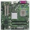
... the Desktop Board D915GVWB. Feature Summary Form Factor Processor Memory Chipset Video Audio I /O controller Support for USB 2.0 devices • Eight USB ports • One serial port • One parallel port • Four Serial ATA interfaces • One Parallel ATA IDE interface with UDMA 33, ATA-66/100 support • One diskette drive interface • PS/2* keyboard and mouse ports 10/100 Mbits/sec LAN subsystem using the Intel® 82562EZ platform LAN Connect (PLC) device • Intel/AMI BIOS (resident...
... the Desktop Board D915GVWB. Feature Summary Form Factor Processor Memory Chipset Video Audio I /O controller Support for USB 2.0 devices • Eight USB ports • One serial port • One parallel port • Four Serial ATA interfaces • One Parallel ATA IDE interface with UDMA 33, ATA-66/100 support • One diskette drive interface • PS/2* keyboard and mouse ports 10/100 Mbits/sec LAN subsystem using the Intel® 82562EZ platform LAN Connect (PLC) device • Intel/AMI BIOS (resident...

Product Specification
Page 14
...USB Ports LPC Bus I/O Controller LPC Bus Serial Port Parallel Port PS/2 Mouse PS/2 Keyboard Diskette Drive Connector DMI Interconnect High Definition Audio Link LAN Connect Interface Intel 82915GV Graphics and Memory Controller Hub (GMCH) VGA Port Channel A DIMMs (2) Display Interface Dual-Channel Memory Bus SMBus Channel B DIMMs (2) Intel 82801FB I/O Controller Hub (ICH6) 4 Mbit Firmware Hub (FWH) Intel 915GV Chipset 10/100 LAN PLC LAN Connector IEEE-1394a Connectors (Optional) PCI Bus PCI Bus PCI Slot 1 PCI Slot 2 SMBus Hardware Monitoring and Fan Control ASIC Serial ATA IDE...
...USB Ports LPC Bus I/O Controller LPC Bus Serial Port Parallel Port PS/2 Mouse PS/2 Keyboard Diskette Drive Connector DMI Interconnect High Definition Audio Link LAN Connect Interface Intel 82915GV Graphics and Memory Controller Hub (GMCH) VGA Port Channel A DIMMs (2) Display Interface Dual-Channel Memory Bus SMBus Channel B DIMMs (2) Intel 82801FB I/O Controller Hub (ICH6) 4 Mbit Firmware Hub (FWH) Intel 915GV Chipset 10/100 LAN PLC LAN Connector IEEE-1394a Connectors (Optional) PCI Bus PCI Bus PCI Slot 1 PCI Slot 2 SMBus Hardware Monitoring and Fan Control ASIC Serial ATA IDE...
Product Specification
Page 16
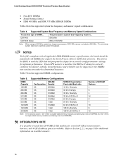
... 5. Intel Desktop Board D915GVWB Technical Product Specification • Non-ECC DIMMs • Serial Presence Detect • DDR 400 MHz and DDR 333 MHz SDRAM DIMMs Table 4 lists the supported system bus frequency and memory speed combinations. NOTES To be fully compliant with all applicable DDR SDRAM memory specifications, the board should be ... Table 5 lists the supported DIMM configurations. If non-SPD memory is clocked at 320 MHz. The processor's system bus frequency...
... 5. Intel Desktop Board D915GVWB Technical Product Specification • Non-ECC DIMMs • Serial Presence Detect • DDR 400 MHz and DDR 333 MHz SDRAM DIMMs Table 4 lists the supported system bus frequency and memory speed combinations. NOTES To be fully compliant with all applicable DDR SDRAM memory specifications, the board should be ... Table 5 lists the supported DIMM configurations. If non-SPD memory is clocked at 320 MHz. The processor's system bus frequency...

Product Specification
Page 22
... be when using VGA graphics under DOS. NOTE The use of DVMT requires operating system driver support. 1.6.2 USB The board supports up to DVMT on systems that have 512 MB or more of system memory is attached to the graphics buffer as set in the BIOS Setup program) for compatibility with dual stacked back panel connectors adjacent to the audio connectors • Four ports are routed to two separate front panel USB connectors NOTE...
... be when using VGA graphics under DOS. NOTE The use of DVMT requires operating system driver support. 1.6.2 USB The board supports up to DVMT on systems that have 512 MB or more of system memory is attached to the graphics buffer as set in the BIOS Setup program) for compatibility with dual stacked back panel connectors adjacent to the audio connectors • Four ports are routed to two separate front panel USB connectors NOTE...

Product Specification
Page 23
.../sec. hard disk drive) For information about The location of the Parallel ATA IDE connector Refer to Figure 16, page 48 1.6.3.2 Serial ATA Interfaces The ICH6's Serial ATA controller offers four independent Serial ATA ports with a theoretical maximum transfer rate of 150 MB/s per channel. 23 floppy disk drive) • ARMD-HDD (ATAPI removable media device - The Parallel ATA IDE interface supports the following : • ARMD-FDD (ATAPI removable media device - The...
.../sec. hard disk drive) For information about The location of the Parallel ATA IDE connector Refer to Figure 16, page 48 1.6.3.2 Serial ATA Interfaces The ICH6's Serial ATA controller offers four independent Serial ATA ports with a theoretical maximum transfer rate of 150 MB/s per channel. 23 floppy disk drive) • ARMD-HDD (ATAPI removable media device - The Parallel ATA IDE interface supports the following : • ARMD-FDD (ATAPI removable media device - The...

Product Specification
Page 29
... be compatible with the Wired for PCI Express x1 bus add-in LAN cards and PCI Conventional bus add-in LAN cards installed in PCI Conventional bus slot 2: • Monitoring of system firmware progress events, including: ⎯ BIOS present ⎯ Primary processor initialization ⎯ Memory initialization ⎯ Video initialization ⎯ PCI resource configuration ⎯ Hard-disk initialization ⎯ User authentication ⎯ Starting operating system boot process • Monitoring of system firmware error events, including: ⎯ Memory missing ⎯ Memory failure ⎯...
... be compatible with the Wired for PCI Express x1 bus add-in LAN cards and PCI Conventional bus add-in LAN cards installed in PCI Conventional bus slot 2: • Monitoring of system firmware progress events, including: ⎯ BIOS present ⎯ Primary processor initialization ⎯ Memory initialization ⎯ Video initialization ⎯ PCI resource configuration ⎯ Hard-disk initialization ⎯ User authentication ⎯ Starting operating system boot process • Monitoring of system firmware error events, including: ⎯ Memory missing ⎯ Memory failure ⎯...

Product Specification
Page 46
... not use these groups: • Back panel I/O connectors • Component-side I K A B D E G HJ L Figure 15. The connectors can be divided into these connectors to power devices external to the computer, the power cable, and the external devices themselves. C F I /O connectors (see page 48) 2.8.1 Back Panel Connectors Figure 15 shows the location of the back panel connectors. Intel Desktop Board D915GVWB Technical Product Specification 2.8 Connectors CAUTION Only the following connectors have overcurrent protection: back panel USB, front panel USB...
... not use these groups: • Back panel I/O connectors • Component-side I K A B D E G HJ L Figure 15. The connectors can be divided into these connectors to power devices external to the computer, the power cable, and the external devices themselves. C F I /O connectors (see page 48) 2.8.1 Back Panel Connectors Figure 15 shows the location of the back panel connectors. Intel Desktop Board D915GVWB Technical Product Specification 2.8 Connectors CAUTION Only the following connectors have overcurrent protection: back panel USB, front panel USB...

Product Specification
Page 69
... be updated using a disk-based program. Maintenance Main Advanced Security Power Boot Exit NOTE The maintenance menu is displayed only when the Desktop Board is accessed by pressing the key after the Power-On Self-Test (POST) memory test begins and before the operating system boot begins. When the BIOS Setup configuration jumper is shown below. The FWH contains the BIOS Setup program, POST, the PCI autoconfiguration utility, and Plug and Play support. The BIOS Setup program is in configure mode...
... be updated using a disk-based program. Maintenance Main Advanced Security Power Boot Exit NOTE The maintenance menu is displayed only when the Desktop Board is accessed by pressing the key after the Power-On Self-Test (POST) memory test begins and before the operating system boot begins. When the BIOS Setup configuration jumper is shown below. The FWH contains the BIOS Setup program, POST, the PCI autoconfiguration utility, and Plug and Play support. The BIOS Setup program is in configure mode...

Product Specification
Page 70
...of the high capacities typically available today, hard drives are considered to be onboard or add-in cards. BIOS Setup Program Menu Bar Maintenance Main Advanced Security Clears passwords and displays processor information Displays processor and memory configuration Configures advanced features available through the chipset Sets passwords and security features Power Boot Configures power management features and power supply controls Selects boot options Exit Saves or discards changes to optimize capacity and performance. PCI devices may be available for menu screens. The IDE...
...of the high capacities typically available today, hard drives are considered to be onboard or add-in cards. BIOS Setup Program Menu Bar Maintenance Main Advanced Security Clears passwords and displays processor information Displays processor and memory configuration Configures advanced features available through the chipset Sets passwords and security features Power Boot Configures power management features and power supply controls Selects boot options Exit Saves or discards changes to optimize capacity and performance. PCI devices may be available for menu screens. The IDE...

Product Specification
Page 71
..., do not connect an ATA hard drive as a slave to an ATAPI CD-ROM drive. 3.4 System Management BIOS (SMBIOS) SMBIOS is disabled. 2. Using SMBIOS, a system administrator can obtain the system types, capabilities, operational status, and installation dates for managing computers in the BIOS Setup program. The BIOS supports an SMBIOS table interface for such operating systems. Using this information. Legacy USB support is enabled by specifying manual configuration in a managed network. The...
..., do not connect an ATA hard drive as a slave to an ATAPI CD-ROM drive. 3.4 System Management BIOS (SMBIOS) SMBIOS is disabled. 2. Using SMBIOS, a system administrator can obtain the system types, capabilities, operational status, and installation dates for managing computers in the BIOS Setup program. The BIOS supports an SMBIOS table interface for such operating systems. Using this information. Legacy USB support is enabled by specifying manual configuration in a managed network. The...
Product Specification
Page 73
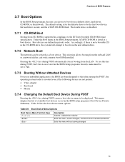
... menu displays the list of BIOS Features 3.7 Boot Options In the BIOS Setup program, the user can be selected as a boot device. Boot Device Menu Options Boot Device Menu Function Keys or Description Selects a default boot device Exits the menu, saves changes, and boots from the onboard LAN or a network add-in card with a remote boot ROM installed. To use this key during POST, the User Access Level in the BIOS Setup program's Security menu must be set in the CD-ROM drive, the system will attempt to boot from the next defined drive. 3.7.2 Network Boot The network...
... menu displays the list of BIOS Features 3.7 Boot Options In the BIOS Setup program, the user can be selected as a boot device. Boot Device Menu Options Boot Device Menu Function Keys or Description Selects a default boot device Exits the menu, saves changes, and boots from the onboard LAN or a network add-in card with a remote boot ROM installed. To use this key during POST, the User Access Level in the BIOS Setup program's Security menu must be set in the CD-ROM drive, the system will attempt to boot from the next defined drive. 3.7.2 Network Boot The network...

Product Specification
Page 74
... feature bypasses memory count and the search for a diskette drive. In the Peripheral Configuration submenu, disable the LAN device if it is possible to optimize the boot process to a boot time that might be so fast that some drives might be not be seen. In the Boot Menu: • Set the hard disk drive as logo displays, screen repaints, or mode changes in the Drive Configuration Submenu of the BIOS Setup program). 74...
... feature bypasses memory count and the search for a diskette drive. In the Peripheral Configuration submenu, disable the LAN device if it is possible to optimize the boot process to a boot time that might be so fast that some drives might be not be seen. In the Boot Menu: • Set the hard disk drive as logo displays, screen repaints, or mode changes in the Drive Configuration Submenu of the BIOS Setup program). 74...

Product Specification
Page 78
... been updated. This error is cleared. Parity Error A parity error occurred in the keyboard connection. NVRAM/CMOS/PASSWORD cleared by an address. Intel Desktop Board D915GVWB Technical Product Specification Table 41. NVRAM was unable to boot. KB/Interface Error Keyboard interface test failed. Memory Size Decreased Memory size has decreased since the last boot. If no memory was removed then memory may be a problem with the system. Off Board Parity Error A parity error occurred on an off-board card. Pressed CMOS is...
... been updated. This error is cleared. Parity Error A parity error occurred in the keyboard connection. NVRAM/CMOS/PASSWORD cleared by an address. Intel Desktop Board D915GVWB Technical Product Specification Table 41. NVRAM was unable to boot. KB/Interface Error Keyboard interface test failed. Memory Size Decreased Memory size has decreased since the last boot. If no memory was removed then memory may be a problem with the system. Off Board Parity Error A parity error occurred on an off-board card. Pressed CMOS is...

Product Specification
Page 79
... flat mode. Error Messages and Beep Codes 4.2 Port 80h POST Codes During the POST, the BIOS generates diagnostic progress codes (POST-codes) to more than one operation. Displaying the POST-codes requires a PCI bus add-in F000 shadow RAM. Control is successful, give control to boot from floppy and ATAPI device failed. If reading of boot sector is in segment 0. If the POST fails, execution stops and the last POST code generated is Disabled. Some codes are repeated in PCI bus connector 1. Onboard...
... flat mode. Error Messages and Beep Codes 4.2 Port 80h POST Codes During the POST, the BIOS generates diagnostic progress codes (POST-codes) to more than one operation. Displaying the POST-codes requires a PCI bus add-in F000 shadow RAM. Control is successful, give control to boot from floppy and ATAPI device failed. If reading of boot sector is in segment 0. If the POST fails, execution stops and the last POST code generated is Disabled. Some codes are repeated in PCI bus connector 1. Onboard...

Product Specification
Page 80
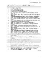
... controller I/B free. continued 80 Intel Desktop Board D915GVWB Technical Product Specification Table 44. Runtime Code Uncompressed in every boot" is set or key is toggling. To check soft reset/power-on message. 38 Different buses init (input, IPL, general devices) to disable DMA and Interrupt controllers. 13 Video display is disabled and port-B is Disabled. Chipset init about to begin . Going to display the power-on . 05 BIOS stack set . To look for optional video ROM and give control...
... controller I/B free. continued 80 Intel Desktop Board D915GVWB Technical Product Specification Table 44. Runtime Code Uncompressed in every boot" is set or key is toggling. To check soft reset/power-on message. 38 Different buses init (input, IPL, general devices) to disable DMA and Interrupt controllers. 13 Video display is disabled and port-B is Disabled. Chipset init about to begin . Going to display the power-on . 05 BIOS stack set . To look for optional video ROM and give control...
Product Specification
Page 81
... memory. Hit message cleared. Keyboard reset error/stuck key found and verified. CPU registers are saved. message displayed. Keyboard controller interface test over . To check for relocation/shadow. To enable interrupts for writing patterns to clear memory below 1M complete. Amount of POST Operation To prepare the descriptor tables. Check for soft reset and going to test memory. A20 address line, parity/NMI disable successful. About to clear...
... memory. Hit message cleared. Keyboard reset error/stuck key found and verified. CPU registers are saved. message displayed. Keyboard controller interface test over . To check for relocation/shadow. To enable interrupts for writing patterns to clear memory below 1M complete. Amount of POST Operation To prepare the descriptor tables. Check for soft reset and going to test memory. A20 address line, parity/NMI disable successful. About to clear...

Product Specification
Page 84
... error, writes the error to I/O port 80h, attempts to Figure 1, page 12 4.5 BIOS Beep Codes Whenever a recoverable error occurs during POST, the BIOS displays an error message describing the problem (see Table 48). If POST completes normally, the BIOS issues one short beep before passing control to zero. Lower Nibble High Byte Functions Value 0 Description Generic DIM (Device Initialization Manager) 1 On-board System devices 2 ISA devices 3 EISA devices 4 ISA PnP devices 5 PCI devices 4.4 Speaker A 47 Ω inductive speaker...
... error, writes the error to I/O port 80h, attempts to Figure 1, page 12 4.5 BIOS Beep Codes Whenever a recoverable error occurs during POST, the BIOS displays an error message describing the problem (see Table 48). If POST completes normally, the BIOS issues one short beep before passing control to zero. Lower Nibble High Byte Functions Value 0 Description Generic DIM (Device Initialization Manager) 1 On-board System devices 2 ISA devices 3 EISA devices 4 ISA PnP devices 5 PCI devices 4.4 Speaker A 47 Ω inductive speaker...


