
Product Specification
Page 5
... 1.2 Overview ...10 1.2.1 Feature Summary 10 1.2.2 Manufacturing Options 11 1.2.3 Board Layout 12 1.2.4 Block Diagram 14 1.3 Online Support ...15 1.4 Processor ...15 1.5 System Memory ...15 1.5.1 Memory Configurations 17 1.6 Intel® 915GV Chipset 21 1.6.1 Intel 915GV Graphics Subsystem 21 1.6.2 USB ...22 1.6.3 IDE Support 23 1.6.4 ... Monitoring and Fan Control ASIC 29 1.11.2 Thermal Monitoring 30 1.11.3 Fan Monitoring 31 1.11.4 Fan Speed Control (Intel® Precision Cooling Technology 31 1.11.5 Chassis Intrusion and Detection 31 1.12 Power Management ...31 1.12.1 ACPI ...32...
... 1.2 Overview ...10 1.2.1 Feature Summary 10 1.2.2 Manufacturing Options 11 1.2.3 Board Layout 12 1.2.4 Block Diagram 14 1.3 Online Support ...15 1.4 Processor ...15 1.5 System Memory ...15 1.5.1 Memory Configurations 17 1.6 Intel® 915GV Chipset 21 1.6.1 Intel 915GV Graphics Subsystem 21 1.6.2 USB ...22 1.6.3 IDE Support 23 1.6.4 ... Monitoring and Fan Control ASIC 29 1.11.2 Thermal Monitoring 30 1.11.3 Fan Monitoring 31 1.11.4 Fan Speed Control (Intel® Precision Cooling Technology 31 1.11.5 Chassis Intrusion and Detection 31 1.12 Power Management ...31 1.12.1 ACPI ...32...

Product Specification
Page 7
... 14. System Memory Map 41 11. DMA Channels ...41 12. Block Diagram...14 3. Component-side Connectors 48 17. Processor Heatsink Airflow 60 24. Location of the Jumper Block 55 21. Thermal Monitoring ...30 13. Connection Diagram for High Definition Audio Subsystem......... 27 10. Board Components ...12 2. Board Components Shown in Figure 1 13 4. LAN Connector LED Locations 28 12. Contents 4 Error Messages and Beep Codes 4.1 BIOS Error...
... 14. System Memory Map 41 11. DMA Channels ...41 12. Block Diagram...14 3. Component-side Connectors 48 17. Processor Heatsink Airflow 60 24. Location of the Jumper Block 55 21. Thermal Monitoring ...30 13. Connection Diagram for High Definition Audio Subsystem......... 27 10. Board Components ...12 2. Board Components Shown in Figure 1 13 4. LAN Connector LED Locations 28 12. Contents 4 Error Messages and Beep Codes 4.1 BIOS Error...

Product Specification
Page 8
... 75 41. Runtime Code Uncompressed in Figure 15 47 17. Beep Codes ...84 viii Processor Fan Connector 50 21. BIOS Setup Configuration Jumper Settings 55 30. BIOS Setup Program Menu Bar 70 38. Bus Initialization Checkpoints 83 46. Intel Desktop Board D915GVWB Technical Product Specification 14. Front Panel Connector 52 27. EMC Regulations ...64...
... 75 41. Runtime Code Uncompressed in Figure 15 47 17. Beep Codes ...84 viii Processor Fan Connector 50 21. BIOS Setup Configuration Jumper Settings 55 30. BIOS Setup Program Menu Bar 70 38. Bus Initialization Checkpoints 83 46. Intel Desktop Board D915GVWB Technical Product Specification 14. Front Panel Connector 52 27. EMC Regulations ...64...

Product Specification
Page 9
... Change 9 1.2 Overview ...10 1.3 Online Support ...15 1.4 Processor ...15 1.5 System Memory ...15 1.6 Intel® 915GV Chipset 21 1.7 PCI Express Connectors 24 1.8 I/O Controller...25 1.9 Audio Subsystem ...26 1.10 LAN Subsystem (Optional 28 1.11 Hardware Management Subsystem 29 1.12 Power Management ...31 1.1 PCI Bus Terminology Change Previous generations of Intel Desktop Boards adds a new technology for add-in...
... Change 9 1.2 Overview ...10 1.3 Online Support ...15 1.4 Processor ...15 1.5 System Memory ...15 1.6 Intel® 915GV Chipset 21 1.7 PCI Express Connectors 24 1.8 I/O Controller...25 1.9 Audio Subsystem ...26 1.10 LAN Subsystem (Optional 28 1.11 Hardware Management Subsystem 29 1.12 Power Management ...31 1.1 PCI Bus Terminology Change Previous generations of Intel Desktop Boards adds a new technology for add-in...

Product Specification
Page 10
...up to 4 GB of system memory Intel® 915GV Chipset, consisting of the Desktop Board D915GVWB. Intel Desktop Board D915GVWB Technical Product Specification 1.2 Overview 1.2.1 Feature Summary Table 1 summarizes the major features of : • Intel® 82915GV Graphics Memory Controller Hub (GMCH) • Intel® 82801FB I/O Controller Hub (... Form Factor (9.60 inches by 9.60 inches [243.84 millimeters by 243.84 millimeters]) Support for an Intel® Pentium® 4 processor in the 4 Mbit FWH) • Support for Advanced Configuration and Power Interface (ACPI), Plug and Play...
...up to 4 GB of system memory Intel® 915GV Chipset, consisting of the Desktop Board D915GVWB. Intel Desktop Board D915GVWB Technical Product Specification 1.2 Overview 1.2.1 Feature Summary Table 1 summarizes the major features of : • Intel® 82915GV Graphics Memory Controller Hub (GMCH) • Intel® 82801FB I/O Controller Hub (... Form Factor (9.60 inches by 9.60 inches [243.84 millimeters by 243.84 millimeters]) Support for an Intel® Pentium® 4 processor in the 4 Mbit FWH) • Support for Advanced Configuration and Power Interface (ACPI), Plug and Play...
Product Specification
Page 13
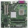
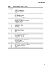
...Board Components Shown in Figure 1 Item/Callout from Figure 1 A B C D E F G H I J K L M N O P Q R S T U V W X Y Z AA BB CC DD EE Description Realtek ALC860 audio codec Front panel audio connector PCI Conventional bus add-in card connectors LAN PLC Rear chassis fan connector Back panel connectors +12V power connector (ATX12V) LGA775 processor socket Hardware monitoring and fan control ASIC Processor... fan connector Intel 82915GV GMCH DIMM Channel A sockets DIMM Channel B...
...Board Components Shown in Figure 1 Item/Callout from Figure 1 A B C D E F G H I J K L M N O P Q R S T U V W X Y Z AA BB CC DD EE Description Realtek ALC860 audio codec Front panel audio connector PCI Conventional bus add-in card connectors LAN PLC Rear chassis fan connector Back panel connectors +12V power connector (ATX12V) LGA775 processor socket Hardware monitoring and fan control ASIC Processor... fan connector Intel 82915GV GMCH DIMM Channel A sockets DIMM Channel B...

Product Specification
Page 14
Block Diagram OM17320 14 PCI Express x1 Slot 1 PCI Express x1 Interface Parallel ATA IDE Connector Parallel ATA IDE Interface LGA775 Processor Socket System Bus (800/533 MHz) USB Back Panel/Front Panel USB Ports LPC Bus I/O Controller LPC Bus Serial Port Parallel Port PS...Codec Mic In/Retasking Jack B Line In/Retasking Jack C Line Out/Retasking Jack D Retasking Jack E [Port 1] Retasking Jack F [Port 2] = connector or socket Figure 2. Intel Desktop Board D915GVWB Technical Product Specification 1.2.4 Block Diagram Figure 2 is a block diagram of the major functional areas of the...
Block Diagram OM17320 14 PCI Express x1 Slot 1 PCI Express x1 Interface Parallel ATA IDE Connector Parallel ATA IDE Interface LGA775 Processor Socket System Bus (800/533 MHz) USB Back Panel/Front Panel USB Ports LPC Bus I/O Controller LPC Bus Serial Port Parallel Port PS...Codec Mic In/Retasking Jack B Line In/Retasking Jack C Line Out/Retasking Jack D Retasking Jack E [Port 1] Retasking Jack F [Port 2] = connector or socket Figure 2. Intel Desktop Board D915GVWB Technical Product Specification 1.2.4 Block Diagram Figure 2 is a block diagram of the major functional areas of the...

Product Specification
Page 15
Intel Desktop Board D915GVWB under "Desktop Board Products" or "Desktop Board Support" Available configurations for the Desktop Board D915GVWB Processor data sheets ICH6 addressing Custom splash screens Audio software and utilities LAN software and drivers Visit this World Wide Web site: http://www.intel.com/design/motherbd http://support.intel.com/support/motherboards/desktop http://developer.intel.com/design/motherbd/wb/wb_available.htm http://www...
Intel Desktop Board D915GVWB under "Desktop Board Products" or "Desktop Board Support" Available configurations for the Desktop Board D915GVWB Processor data sheets ICH6 addressing Custom splash screens Audio software and utilities LAN software and drivers Visit this World Wide Web site: http://www.intel.com/design/motherbd http://support.intel.com/support/motherboards/desktop http://developer.intel.com/design/motherbd/wb/wb_available.htm http://www...
Product Specification
Page 16
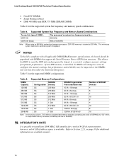
DDR 400 800 MHz DDR 333 (Note) 800 or 533 MHz Note: When using an 800 MHz system bus frequency processor, DDR 333 memory is installed, the BIOS will attempt to correctly configure the memory settings, but performance and reliability may be ...optimize system throughput. Table 4. This minimizes system latencies to install four 2048 MB (2 GB) modules for additional information on available memory. 16 Table 5. Intel Desktop Board D915GVWB Technical Product Specification • Non-ECC DIMMs • Serial Presence Detect • DDR 400 MHz and DDR 333 MHz SDRAM DIMMs Table 4 lists...
DDR 400 800 MHz DDR 333 (Note) 800 or 533 MHz Note: When using an 800 MHz system bus frequency processor, DDR 333 memory is installed, the BIOS will attempt to correctly configure the memory settings, but performance and reliability may be ...optimize system throughput. Table 4. This minimizes system latencies to install four 2048 MB (2 GB) modules for additional information on available memory. 16 Table 5. Intel Desktop Board D915GVWB Technical Product Specification • Non-ECC DIMMs • Serial Presence Detect • DDR 400 MHz and DDR 333 MHz SDRAM DIMMs Table 4 lists...

Product Specification
Page 23
...four independent Serial ATA ports with a theoretical maximum transfer rate of 150 MB/s per channel. 23 Product Description 1.6.3 IDE Support The board provides five IDE interface connectors: • One parallel ATA IDE connector that supports two devices • Four serial ATA IDE connectors that...Interface The ICH6's Parallel ATA IDE controller has one of the following modes: • Programmed I/O (PIO): processor controls data transfer. • 8237-style DMA: DMA offloads the processor, supporting transfer rates of up to 16 MB/sec. • Ultra DMA: DMA protocol on IDE bus supporting...
...four independent Serial ATA ports with a theoretical maximum transfer rate of 150 MB/s per channel. 23 Product Description 1.6.3 IDE Support The board provides five IDE interface connectors: • One parallel ATA IDE connector that supports two devices • Four serial ATA IDE connectors that...Interface The ICH6's Parallel ATA IDE controller has one of the following modes: • Programmed I/O (PIO): processor controls data transfer. • 8237-style DMA: DMA offloads the processor, supporting transfer rates of up to 16 MB/sec. • Ultra DMA: DMA protocol on IDE bus supporting...

Product Specification
Page 29
... hardware monitoring and fan control ASIC include: • Internal ambient temperature sensor 29 The Desktop Board has several hardware management features, including the following ASF support for PCI Express x1 bus ... bus slot 2: • Monitoring of system firmware progress events, including: ⎯ BIOS present ⎯ Primary processor initialization ⎯ Memory initialization ⎯ Video initialization ⎯ PCI resource configuration ⎯ Hard-disk initialization ⎯... Subsystem The hardware management features enable the board to boot from Intel's World Wide Web site.
... hardware monitoring and fan control ASIC include: • Internal ambient temperature sensor 29 The Desktop Board has several hardware management features, including the following ASF support for PCI Express x1 bus ... bus slot 2: • Monitoring of system firmware progress events, including: ⎯ BIOS present ⎯ Primary processor initialization ⎯ Memory initialization ⎯ Video initialization ⎯ PCI resource configuration ⎯ Hard-disk initialization ⎯... Subsystem The hardware management features enable the board to boot from Intel's World Wide Web site.
Product Specification
Page 30
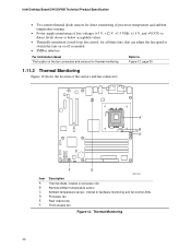
Thermal Monitoring 30 Intel Desktop Board D915GVWB Technical Product Specification • Two remote thermal diode sensors for direct monitoring of processor temperature and ambient temperature sensing • Power supply monitoring of five voltages (+5 V, +12 V, +3.3 VSB, +1.5 V, and +VCCP) to detect ...Figure 12 shows the location of the sensors and fan connectors. 3 1 A CB 4 1 D 1 3 Item A B C D E F F E OM17322 Description Thermal diode, located on processor die Remote ambient temperature sensor Ambient temperature sensor, internal to hardware monitoring and fan control ASIC...
Thermal Monitoring 30 Intel Desktop Board D915GVWB Technical Product Specification • Two remote thermal diode sensors for direct monitoring of processor temperature and ambient temperature sensing • Power supply monitoring of five voltages (+5 V, +12 V, +3.3 VSB, +1.5 V, and +VCCP) to detect ...Figure 12 shows the location of the sensors and fan connectors. 3 1 A CB 4 1 D 1 3 Item A B C D E F F E OM17322 Description Thermal diode, located on processor die Remote ambient temperature sensor Ambient temperature sensor, internal to hardware monitoring and fan control ASIC...

Product Specification
Page 31
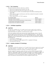
...; LAN wake capabilities ⎯ Instantly Available PC technology ⎯ Resume on the chassis that processor fan speed control remain enabled (default BIOS setting) when using Intel® Desktop Utilities, LANDesk* software, or thirdparty software. When the chassis cover is removed, the mechanical ...controlled chassis and processor fans at full speed if it is attached to the chassis intrusion connector. The overall system noise reduction will result in chassis fans always operating at several levels, including: • Software support through the desktop board BIOS. The ...
...; LAN wake capabilities ⎯ Instantly Available PC technology ⎯ Resume on the chassis that processor fan speed control remain enabled (default BIOS setting) when using Intel® Desktop Utilities, LANDesk* software, or thirdparty software. When the chassis cover is removed, the mechanical ...controlled chassis and processor fans at full speed if it is attached to the chassis intrusion connector. The overall system noise reduction will result in chassis fans always operating at several levels, including: • Software support through the desktop board BIOS. The ...

Product Specification
Page 33
working state S0 - Processor stopped S3 - Context saved to disk. Context saved to RAM. mechanical off . No power D3 - Notes: 1. Total system power is disabled by the system chassis' ..., software, drivers, and peripherals must fully support ACPI wake events. 33 sleeping state G1 - sleeping state S4 - Dependent on the system configuration, including add-in boards and peripherals powered by default in the BIOS Setup program. Full power > 30 W G1 - device specification specific. no power except for wake-up the computer...
working state S0 - Processor stopped S3 - Context saved to disk. Context saved to RAM. mechanical off . No power D3 - Notes: 1. Total system power is disabled by the system chassis' ..., software, drivers, and peripherals must fully support ACPI wake events. 33 sleeping state G1 - sleeping state S4 - Dependent on the system configuration, including add-in boards and peripherals powered by default in the BIOS Setup program. Full power > 30 W G1 - device specification specific. no power except for wake-up the computer...
Product Specification
Page 35
...quickly returns to provide adequate standby current when implementing LAN wake capabilities can damage the power supply. Instantly Available PC technology enables the board to enter the ACPI S3 (Suspend-to provide adequate standby current when implementing Instantly Available PC technology can damage the power supply. ... about The location of the fan connectors The location of the fan connectors and sensors for thermal monitoring The signal names of the processor fan connector The signal names of the chassis fan connectors Refer to Figure 16, page 48 Figure 12, page 30 Table 20,...
...quickly returns to provide adequate standby current when implementing LAN wake capabilities can damage the power supply. Instantly Available PC technology enables the board to enter the ACPI S3 (Suspend-to provide adequate standby current when implementing Instantly Available PC technology can damage the power supply. ... about The location of the fan connectors The location of the fan connectors and sensors for thermal monitoring The signal names of the processor fan connector The signal names of the chassis fan connectors Refer to Figure 16, page 48 Figure 12, page 30 Table 20,...
Product Specification
Page 50
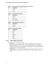
a 2 x 12 connector. Failure to the processor voltage regulator and must always be used on the rightmost pins of ATX12V power supplies with either 2 x 10 or 2 x 12 main power cables. This connector is compatible with a 2 x 10 main power cable, attach that cable on Intel Desktop boards. When using a power supply with 2 x 10 connectors previously used . a 2 x 2 connector...
a 2 x 12 connector. Failure to the processor voltage regulator and must always be used on the rightmost pins of ATX12V power supplies with either 2 x 10 or 2 x 12 main power cables. This connector is compatible with a 2 x 10 main power cable, attach that cable on Intel Desktop boards. When using a power supply with 2 x 10 connectors previously used . a 2 x 2 connector...
Product Specification
Page 55
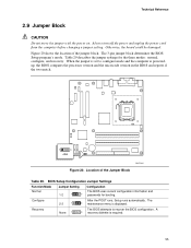
...Location of the jumper block. The 3-pin jumper block determines the BIOS Setup program's mode. A 3 recovery diskette is poweredup, the BIOS compares the processor version and the microcode version in the BIOS and reports if the two match. 1 3 J8J4 OM17325 Figure 20. Technical Reference 2.9 Jumper Block CAUTION...modes: normal, configure, and recovery. Configure 2-3 1 After the POST runs, Setup runs automatically. The 3 maintenance menu is displayed. Otherwise, the board could be damaged. Recovery None 1 The BIOS attempts to configure mode and the computer is required. 55
...Location of the jumper block. The 3-pin jumper block determines the BIOS Setup program's mode. A 3 recovery diskette is poweredup, the BIOS compares the processor version and the microcode version in the BIOS and reports if the two match. 1 3 J8J4 OM17325 Figure 20. Technical Reference 2.9 Jumper Block CAUTION...modes: normal, configure, and recovery. Configure 2-3 1 After the POST runs, Setup runs automatically. The 3 maintenance menu is displayed. Otherwise, the board could be damaged. Recovery None 1 The BIOS attempts to configure mode and the computer is required. 55
Product Specification
Page 58
... datasheets for each add-in cards. Fan Connector Current Capability Fan Connector Processor fan Front chassis fan Rear chassis fan Maximum Available Current 1000 mA 600 mA 600 mA 58 Intel Desktop Board D915GVWB Technical Product Specification 2.11 Electrical Considerations 2.11.1 DC Loading Table ...30 lists the DC loading characteristics of the fan connectors. Table 31 lists the current capability of the board. Minimum values assume a light load...
... datasheets for each add-in cards. Fan Connector Current Capability Fan Connector Processor fan Front chassis fan Rear chassis fan Maximum Available Current 1000 mA 600 mA 600 mA 58 Intel Desktop Board D915GVWB Technical Product Specification 2.11 Electrical Considerations 2.11.1 DC Loading Table ...30 lists the DC loading characteristics of the fan connectors. Table 31 lists the current capability of the board. Minimum values assume a light load...
Product Specification
Page 60
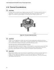
... Figure 23. CAUTION Ensure that have been tested with a maximum internal ambient temperature of 38 oC at the processor fan inlet is a requirement. Intel Desktop Board D915GVWB Technical Product Specification 2.12 Thermal Considerations CAUTION A chassis with Intel desktop boards please refer to the following the instructions presented in this document will result in a system with the reader...
... Figure 23. CAUTION Ensure that have been tested with a maximum internal ambient temperature of 38 oC at the processor fan inlet is a requirement. Intel Desktop Board D915GVWB Technical Product Specification 2.12 Thermal Considerations CAUTION A chassis with Intel desktop boards please refer to the following the instructions presented in this document will result in a system with the reader...
Product Specification
Page 61
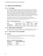
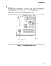
A B D C OM17327 Item A B C D Description Processor voltage regulator area Processor Intel 82915GV GMCH Intel 82801FB ICH6 Figure 24. Localized High Temperature Zones 61 Technical Reference CAUTION Ensure that proper airflow is maintained in an open chassis. Figure 24 shows the locations of up to the voltage regulator circuit. The processor voltage regulator area (item A in Figure 24) can reach a temperature of the localized high temperature zones. Failure to do so may result in damage to 85 oC in the processor voltage regulator circuit.
A B D C OM17327 Item A B C D Description Processor voltage regulator area Processor Intel 82915GV GMCH Intel 82801FB ICH6 Figure 24. Localized High Temperature Zones 61 Technical Reference CAUTION Ensure that proper airflow is maintained in an open chassis. Figure 24 shows the locations of up to the voltage regulator circuit. The processor voltage regulator area (item A in Figure 24) can reach a temperature of the localized high temperature zones. Failure to do so may result in damage to 85 oC in the processor voltage regulator circuit.


