Product Guide
Page 5
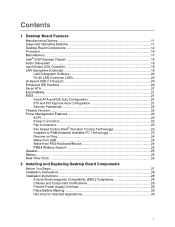
Contents 1 Desktop Board Features Manufacturing Options ...11 Supported Operating Systems 11 Desktop Board Components 12 Processor ...16 Main Memory ...17 Intel® 915P Express Chipset 18 Audio Subsystem ...18 Input/Output (I/O) Controller 19 LAN Subsystem (Optional 19 LAN Subsystem Software ...21 Security Passwords ...22 Chassis Intrusion...22 Power Management Features 22 ACPI...22 Power Connectors ...22 Fan Connectors...23 Fan Speed Control (Intel® Precision Cooling Technology 23 Suspend to RAM (Instantly Available PC Technology 23 Resume on Ring...24 Wake from USB...24 Wake ...
Contents 1 Desktop Board Features Manufacturing Options ...11 Supported Operating Systems 11 Desktop Board Components 12 Processor ...16 Main Memory ...17 Intel® 915P Express Chipset 18 Audio Subsystem ...18 Input/Output (I/O) Controller 19 LAN Subsystem (Optional 19 LAN Subsystem Software ...21 Security Passwords ...22 Chassis Intrusion...22 Power Management Features 22 ACPI...22 Power Connectors ...22 Fan Connectors...23 Fan Speed Control (Intel® Precision Cooling Technology 23 Suspend to RAM (Instantly Available PC Technology 23 Resume on Ring...24 Wake from USB...24 Wake ...

Product Guide
Page 6
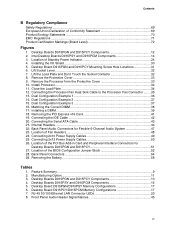
Intel Desktop Board D915PGN/D915PSY/D915PCY/D915PCM Product Guide Installing the I/O Shield ...30 Installing and Removing the Desktop Board 31 Installing and Removing a Processor 32 Installing a Processor 32 Installing the Processor Fan Heat Sink 34 Connecting the Processor Fan Heat Sink Cable 35 Removing the Processor 35 ...Jumper Block 52 Clearing Passwords ...53 Back Panel Connectors...54 Replacing the Battery ...55 3 BIOS Updating the BIOS with the Intel® Express BIOS Update Utility 59 Updating the BIOS with the Iflash Memory Update Utility 59 Obtaining the BIOS Update File...
Intel Desktop Board D915PGN/D915PSY/D915PCY/D915PCM Product Guide Installing the I/O Shield ...30 Installing and Removing the Desktop Board 31 Installing and Removing a Processor 32 Installing a Processor 32 Installing the Processor Fan Heat Sink 34 Connecting the Processor Fan Heat Sink Cable 35 Removing the Processor 35 ...Jumper Block 52 Clearing Passwords ...53 Back Panel Connectors...54 Replacing the Battery ...55 3 BIOS Updating the BIOS with the Intel® Express BIOS Update Utility 59 Updating the BIOS with the Iflash Memory Update Utility 59 Obtaining the BIOS Update File...
Product Guide
Page 7
...11 3. Front Panel Audio Header Signal Names 45 vii Desktop Board D915PGN and D915PCY Mounting Screw Hole Locations 31 6. Remove the Processor from the Protective Cover 33 10. Location of Standby Power Indicator 24 4. Location of the PCI Bus Add-in Card and ... Regulations ...71 Product Certification Markings (Board Level 72 Figures 1. Remove the Protective Cover 33 9. Dual Configuration Example 3 37 16. Intel Desktop Boards D915PSY and D915PCM Components 14 3. Back Panel Audio Connectors for Desktop Boards D915PGN and D915PCY 51 27. Connecting the IDE...
...11 3. Front Panel Audio Header Signal Names 45 vii Desktop Board D915PGN and D915PCY Mounting Screw Hole Locations 31 6. Remove the Processor from the Protective Cover 33 10. Location of Standby Power Indicator 24 4. Location of the PCI Bus Add-in Card and ... Regulations ...71 Product Certification Markings (Board Level 72 Figures 1. Remove the Protective Cover 33 9. Dual Configuration Example 3 37 16. Intel Desktop Boards D915PSY and D915PCM Components 14 3. Back Panel Audio Connectors for Desktop Boards D915PGN and D915PCY 51 27. Connecting the IDE...
Product Guide
Page 9
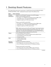
Feature Summary Processor Support for an Intel® Pentium® 4 processor in the LGA775 package Main Memory Desktop boards D915PGN and D915PSY: • Four 184-pin, 2.5 V SDRAM Dual Inline Memory Module (DIMM) sockets • 400/333... Realtek codec Desktop boards D915PGN and D915PCY: • Four PCI bus add-in card connectors (SMBus routed to the Intel World Wide Web site at: http://support.intel.com/support/motherboards/desktop/ Intel® 915P Express Chipset consisting of system memory Chipset Audio Expansion Capabilities NOTE: System resources (such as PCI and PCI...
Feature Summary Processor Support for an Intel® Pentium® 4 processor in the LGA775 package Main Memory Desktop boards D915PGN and D915PSY: • Four 184-pin, 2.5 V SDRAM Dual Inline Memory Module (DIMM) sockets • 400/333... Realtek codec Desktop boards D915PGN and D915PCY: • Four PCI bus add-in card connectors (SMBus routed to the Intel World Wide Web site at: http://support.intel.com/support/motherboards/desktop/ Intel® 915P Express Chipset consisting of system memory Chipset Audio Expansion Capabilities NOTE: System resources (such as PCI and PCI...

Product Guide
Page 10
... inputs used to monitor fan activity • Remote diode temperature sensing • Intel® Precision Cooling Technology fan speed control that automatically adjusts processor fan speeds based on processor temperature and chassis fan speeds based on system temperature • Voltage sensing to ...detect out of range values Related Links For more information about Intel Desktop Board D915PGN/D915PSY/D915PCY/D915PCM...
... inputs used to monitor fan activity • Remote diode temperature sensing • Intel® Precision Cooling Technology fan speed control that automatically adjusts processor fan speeds based on processor temperature and chassis fan speeds based on system temperature • Voltage sensing to ...detect out of range values Related Links For more information about Intel Desktop Board D915PGN/D915PSY/D915PCY/D915PCM...
Product Guide
Page 13
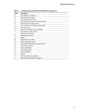
... x1 connectors Front panel audio header PCI Express x16 connector Rear chassis fan header 1 (fan speed control) Alternate power connector (1x4) 12 V processor core voltage connector (2x2) Processor socket Processor fan header (4-pin, controlled) Main power connector (2x12) Diskette drive connector Primary IDE connector Battery Chassis intrusion header BIOS configuration jumper Front chassis...
... x1 connectors Front panel audio header PCI Express x16 connector Rear chassis fan header 1 (fan speed control) Alternate power connector (1x4) 12 V processor core voltage connector (2x2) Processor socket Processor fan header (4-pin, controlled) Main power connector (2x12) Diskette drive connector Primary IDE connector Battery Chassis intrusion header BIOS configuration jumper Front chassis...

Product Guide
Page 15
...Express x16 connector Rear chassis fan header (fan speed control) Alternate power connector (1x4) 12 V processor core voltage connector (2x2) Processor socket Processor fan header (4-pin, controlled) Main power connector (2x12) Diskette drive connector Primary IDE connector Battery ...: • Intel Desktop Board D915PGN/D915PSY/ D915PCY/D915PCM http://www.intel.com/design/motherbd http://support.intel.com/support/motherboards/desktop • Supported processors http://support.intel.com/support/motherboards/desktop • Audio software and utilities http://www.intel.com/design/motherbd...
...Express x16 connector Rear chassis fan header (fan speed control) Alternate power connector (1x4) 12 V processor core voltage connector (2x2) Processor socket Processor fan header (4-pin, controlled) Main power connector (2x12) Diskette drive connector Primary IDE connector Battery ...: • Intel Desktop Board D915PGN/D915PSY/ D915PCY/D915PCM http://www.intel.com/design/motherbd http://support.intel.com/support/motherboards/desktop • Supported processors http://support.intel.com/support/motherboards/desktop • Audio software and utilities http://www.intel.com/design/motherbd...
Product Guide
Page 16
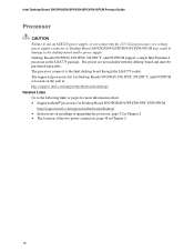
... the web at: http://support.intel.com/support/motherboards/desktop/ Related Links Go to the following links or pages for more information about: • Supported Intel® processors for Desktop Board D915PGN/D915PSY/D915PCY/D915PCM http://support.intel.com/support/motherboards/desktop/ •...; Instructions on installing or upgrading the processor, page 32 in Chapter 2 • The location of ...
... the web at: http://support.intel.com/support/motherboards/desktop/ Related Links Go to the following links or pages for more information about: • Supported Intel® processors for Desktop Board D915PGN/D915PSY/D915PCY/D915PCM http://support.intel.com/support/motherboards/desktop/ •...; Instructions on installing or upgrading the processor, page 32 in Chapter 2 • The location of ...
Product Guide
Page 17
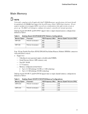
...dual or single channel memory configurations defined in Table 5. Desktop Board D915PGN/D915PSY Memory Configurations Memory Speed DDR 400 Processor Pentium 4 processor DDR 333 Pentium 4 processor FSB Frequency (MHz) 800 533 800 533 Memory Speed Outcome (MHz) 400 400 333 333 Four 184-pin... Detect (SPD) data structure. Table 6. Table 5. Desktop Board Features Main Memory NOTE To be fully compliant with all applicable Intel® SDRAM memory specifications, the board should be populated with gold-plated contacts. • Support for normal operation. Desktop Board...
...dual or single channel memory configurations defined in Table 5. Desktop Board D915PGN/D915PSY Memory Configurations Memory Speed DDR 400 Processor Pentium 4 processor DDR 333 Pentium 4 processor FSB Frequency (MHz) 800 533 800 533 Memory Speed Outcome (MHz) 400 400 333 333 Four 184-pin... Detect (SPD) data structure. Table 6. Table 5. Desktop Board Features Main Memory NOTE To be fully compliant with all applicable Intel® SDRAM memory specifications, the board should be populated with gold-plated contacts. • Support for normal operation. Desktop Board...

Product Guide
Page 20
...protocols • Laser Servo (LS-120) drives 20 Enhanced IDE Interface The ICH6's IDE interface handles the exchange of information between the processor and peripheral devices like hard disks, CD-ROM drives, and Iomega Zip* drives inside the computer. Yellow Off LAN link is established....supports up and the 10/100 Ethernet LAN subsystem is communicating with another computer on Intel's World Wide Web site at USB 1.1 speeds. USB 1.1 devices will function normally at : http://support.intel.com/support/motherboards/desktop RJ-45 LAN Connector LEDs Two LEDs are backward compatible with...
...protocols • Laser Servo (LS-120) drives 20 Enhanced IDE Interface The ICH6's IDE interface handles the exchange of information between the processor and peripheral devices like hard disks, CD-ROM drives, and Iomega Zip* drives inside the computer. Yellow Off LAN link is established....supports up and the 10/100 Ethernet LAN subsystem is communicating with another computer on Intel's World Wide Web site at USB 1.1 speeds. USB 1.1 devices will function normally at : http://support.intel.com/support/motherboards/desktop RJ-45 LAN Connector LEDs Two LEDs are backward compatible with...
Product Guide
Page 23
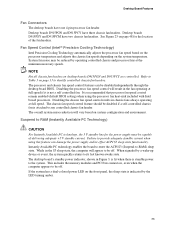
Fan Speed Control (Intel® Precision Cooling Technology) Intel Precision Cooling Technology automatically adjusts the processor fan speed based on the processor temperature and adjusts the chassis fan speeds depending on page 13 to be off . The overall system noise reduction ...can be off . Failure to Table 3 on the system temperature. Refer to provide adequate standby current when using the processor fan heat-sink included with Intel boxed processors. Desktop boards D915PGN and D915PCY have three chassis fan headers. This includes the memory modules and PCI bus connectors, ...
Fan Speed Control (Intel® Precision Cooling Technology) Intel Precision Cooling Technology automatically adjusts the processor fan speed based on the processor temperature and adjusts the chassis fan speeds depending on page 13 to be off . The overall system noise reduction ...can be off . Failure to Table 3 on the system temperature. Refer to provide adequate standby current when using the processor fan heat-sink included with Intel boxed processors. Desktop boards D915PGN and D915PCY have three chassis fan headers. This includes the memory modules and PCI bus connectors, ...
Product Guide
Page 27
... Replacing Desktop Board Components This chapter tells you how to: • Install the I/O shield • Install and remove the desktop board • Install and remove a processor and memory • Install and remove a x16 PCI Express card • Connect the IDE and Serial ATA cables • Connect the front panel header •...
... Replacing Desktop Board Components This chapter tells you how to: • Install the I/O shield • Install and remove the desktop board • Install and remove a processor and memory • Install and remove a x16 PCI Express card • Connect the IDE and Serial ATA cables • Connect the front panel header •...
Product Guide
Page 28
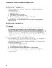
...applicable, are not Class B EMC compliant before integration, then EMC testing is required on the chassis • Hot components (like processors, voltage regulators, and heat sinks) • Damage to qualified technical personnel. If the instructions for associated modules, contact the ...and adhere to meet safety and regulatory requirements when installing this board. Intel Desktop Board D915PGN/D915PSY/D915PCY/D915PCM Product Guide Installation Precautions When you install and test the Intel desktop board, observe all of these instructions and the instructions supplied with...
...applicable, are not Class B EMC compliant before integration, then EMC testing is required on the chassis • Hot components (like processors, voltage regulators, and heat sinks) • Damage to qualified technical personnel. If the instructions for associated modules, contact the ...and adhere to meet safety and regulatory requirements when installing this board. Intel Desktop Board D915PGN/D915PSY/D915PCY/D915PCM Product Guide Installation Precautions When you install and test the Intel desktop board, observe all of these instructions and the instructions supplied with...
Product Guide
Page 32
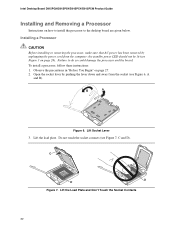
Intel Desktop Board D915PGN/D915PSY/D915PCY/D915PCM Product Guide Installing and Removing a Processor Instructions on how to install the processor to do so could damage the processor and the board. Lift the load plate. To install a processor, follow these instructions: 1. Lift Socket Lever 3. Installing a Processor CAUTION Before installing or removing the processor, make sure that AC power has...
Intel Desktop Board D915PGN/D915PSY/D915PCY/D915PCM Product Guide Installing and Removing a Processor Instructions on how to install the processor to do so could damage the processor and the board. Lift the load plate. To install a processor, follow these instructions: 1. Lift Socket Lever 3. Installing a Processor CAUTION Before installing or removing the processor, make sure that AC power has...
Product Guide
Page 33
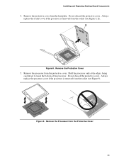
... socket (see Figure 9). Remove the Protective Cover 5. Do not discard the protective cover. Remove the processor from the load plate. Installing and Replacing Desktop Board Components 4. Hold the processor only at the edges, being careful not to touch the bottom of the processor. Remove the protective cover from the protective cover. Remove the...
... socket (see Figure 9). Remove the Protective Cover 5. Do not discard the protective cover. Remove the processor from the load plate. Installing and Replacing Desktop Board Components 4. Hold the processor only at the edges, being careful not to touch the bottom of the processor. Remove the protective cover from the protective cover. Remove the...
Product Guide
Page 34
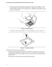
... cutouts (see (Figure 10, H). Pressing down without tilting or sliding the processor in Figure 10. Install Processor 7. Close the Load Plate Installing the Processor Fan Heat Sink Desktop Board D915PGN/D915PSY/D915PCY/D915PCM has an integrated processor fan heat sink retention mechanism (RM). Intel Desktop Board D915PGN/D915PSY/D915PCY/D915PCM Product Guide 6. G G HF H F Figure 10...
... cutouts (see (Figure 10, H). Pressing down without tilting or sliding the processor in Figure 10. Install Processor 7. Close the Load Plate Installing the Processor Fan Heat Sink Desktop Board D915PGN/D915PSY/D915PCY/D915PCM has an integrated processor fan heat sink retention mechanism (RM). Intel Desktop Board D915PGN/D915PSY/D915PCY/D915PCM Product Guide 6. G G HF H F Figure 10...
Product Guide
Page 35
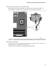
... Components Connecting the Processor Fan Heat Sink Cable Connect the processor fan heat sink cable to the processor installation manual or the Intel World Wide Web site at: http://support.intel.com/support/processors/pentium4/intnotes478.htm 35 OM16881 Figure 12. Connecting the Processor Fan Heat Sink Cable to the Processor Fan Connector Removing the Processor For instruction on...
... Components Connecting the Processor Fan Heat Sink Cable Connect the processor fan heat sink cable to the processor installation manual or the Intel World Wide Web site at: http://support.intel.com/support/processors/pentium4/intnotes478.htm 35 OM16881 Figure 12. Connecting the Processor Fan Heat Sink Cable to the Processor Fan Connector Removing the Processor For instruction on...
Product Guide
Page 48
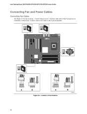
Intel Desktop Board D915PGN/D915PSY/D915PCY/D915PCM Product Guide Connecting Fan and Power Cables Connecting Fan Cables See Figure 23 for fan locations. Connect the processor's fan heat sink cable to the 3-pin fan headers. 3 21 A 3 21 B 43 2 1 A Figure 23. Location of Fan Headers 43 2 1 B OM16844 48 Connect chassis fan cables to the 4-pin processor fan header on the board.
Intel Desktop Board D915PGN/D915PSY/D915PCY/D915PCM Product Guide Connecting Fan and Power Cables Connecting Fan Cables See Figure 23 for fan locations. Connect the processor's fan heat sink cable to the 3-pin fan headers. 3 21 A 3 21 B 43 2 1 A Figure 23. Location of Fan Headers 43 2 1 B OM16844 48 Connect chassis fan cables to the 4-pin processor fan header on the board.
Product Guide
Page 49
Connect the 12 V processor core voltage power supply cable to 75 W. Use of the power connectors for a 2x10 power supply cable. 1 2 2X10 Figure 24. Connect the main power supply .... OM16850 49 Installing and Replacing Desktop Board Components Connecting Power Cables CAUTION Failure to use an ATX12V power supply, or not connecting the 12 V (2x2) processor core voltage power supply connector to the desktop board may result in "Before You Begin" on the desktop board is recommended with ATX12V power supplies...
Connect the 12 V processor core voltage power supply cable to 75 W. Use of the power connectors for a 2x10 power supply cable. 1 2 2X10 Figure 24. Connect the main power supply .... OM16850 49 Installing and Replacing Desktop Board Components Connecting Power Cables CAUTION Failure to use an ATX12V power supply, or not connecting the 12 V (2x2) processor core voltage power supply connector to the desktop board may result in "Before You Begin" on the desktop board is recommended with ATX12V power supplies...
Product Guide
Page 50
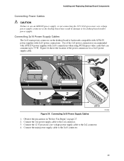
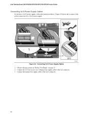
Connect the 12 V processor core voltage power supply cable to the 2x12 connector. Connect the main power supply cable to the 2x2 connector. 3. Connecting 2x12 Power Supply Cables 1. Observe the precautions in "Before You Begin" on page 27. 2. Figure 25 shows the location of the power connectors for a 2x12 power supply. 1 2 2X12 Figure 25. Intel Desktop Board D915PGN/D915PSY/D915PCY/D915PCM Product Guide Connecting 2x12 Power Supply Cables If you have a 2x12 power supply, follow the instruction below. OM16851 50
Connect the 12 V processor core voltage power supply cable to the 2x12 connector. Connect the main power supply cable to the 2x2 connector. 3. Connecting 2x12 Power Supply Cables 1. Observe the precautions in "Before You Begin" on page 27. 2. Figure 25 shows the location of the power connectors for a 2x12 power supply. 1 2 2X12 Figure 25. Intel Desktop Board D915PGN/D915PSY/D915PCY/D915PCM Product Guide Connecting 2x12 Power Supply Cables If you have a 2x12 power supply, follow the instruction below. OM16851 50


