Product Specification
Page 5
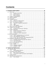
... Memory Configurations 17 1.6 Intel® G31 Express Chipset 19 1.6.1 Intel G31 Graphics Subsystem 19 1.6.2 USB 20 1.6.3 IDE Support 20 1.7 Real-Time Clock Subsystem 22 1.8 Legacy I/O Controller 22 1.8.1 Keyboard and Mouse Interface 22 1.9 Audio Subsystem 23 1.9.1 Audio Subsystem Software 23 1.9.2 Audio Connectors 23 1.9.3 4-Channel Audio Subsystem 24 1.10 LAN Subsystem 25 1.10.1 Intel® 82562G Ethernet Controller 25 1.10.2 LAN Subsystem Software 25 1.10.3 RJ-45 LAN Connector with Integrated LEDs 26 1.11 Hardware Management Subsystem 27 1.11.1 Hardware Monitoring and Fan...
... Memory Configurations 17 1.6 Intel® G31 Express Chipset 19 1.6.1 Intel G31 Graphics Subsystem 19 1.6.2 USB 20 1.6.3 IDE Support 20 1.7 Real-Time Clock Subsystem 22 1.8 Legacy I/O Controller 22 1.8.1 Keyboard and Mouse Interface 22 1.9 Audio Subsystem 23 1.9.1 Audio Subsystem Software 23 1.9.2 Audio Connectors 23 1.9.3 4-Channel Audio Subsystem 24 1.10 LAN Subsystem 25 1.10.1 Intel® 82562G Ethernet Controller 25 1.10.2 LAN Subsystem Software 25 1.10.3 RJ-45 LAN Connector with Integrated LEDs 26 1.11 Hardware Management Subsystem 27 1.11.1 Hardware Monitoring and Fan...
Product Specification
Page 6
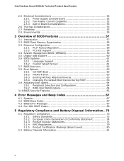
...3.3.2 PCI IDE Support 59 3.4 System Management BIOS (SMBIOS 59 3.5 Legacy USB Support 60 3.6 BIOS Updates 61 3.6.1 Language Support 61 3.6.2 Custom Splash Screen 61 3.7 BIOS Recovery 62 3.8 Boot Options 63 3.8.1 CD-ROM Boot 63 3.8.2 Network Boot 63 3.8.3 Booting Without Attached Devices 63 3.8.4 Changing the Default Boot Device During POST 63 3.9 Adjusting Boot Speed 64 3.9.1 Peripheral Selection and Configuration 64 3.9.2 BIOS Boot Optimizations 64 3.10 BIOS Security Features 65 4 Error Messages and Beep Codes 67 4.1 Speaker 67 4.2 BIOS Beep Codes 67 4.3 BIOS Error Messages...
...3.3.2 PCI IDE Support 59 3.4 System Management BIOS (SMBIOS 59 3.5 Legacy USB Support 60 3.6 BIOS Updates 61 3.6.1 Language Support 61 3.6.2 Custom Splash Screen 61 3.7 BIOS Recovery 62 3.8 Boot Options 63 3.8.1 CD-ROM Boot 63 3.8.2 Network Boot 63 3.8.3 Booting Without Attached Devices 63 3.8.4 Changing the Default Boot Device During POST 63 3.9 Adjusting Boot Speed 64 3.9.1 Peripheral Selection and Configuration 64 3.9.2 BIOS Boot Optimizations 64 3.10 BIOS Security Features 65 4 Error Messages and Beep Codes 67 4.1 Speaker 67 4.2 BIOS Beep Codes 67 4.3 BIOS Error Messages...
Product Specification
Page 7
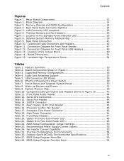
... Standby Power Indicator LED 35 Figure 8. Power States and Targeted System Power 30 Table 8. Detailed System Memory Address Map 38 Figure 9. Desktop Board DG31GL Environmental Specifications 55 Table 27. States for Front Panel USB Headers 49 Figure 13. LAN Connector LED Locations 26 Figure 6. Main Power Connector 46 Table 19. System Memory Map 39 Table 10. BIOS Setup Configuration Jumper Settings 50 Table 23. Processor (4-Pin) Fan Header 45 Table 17. Rear Chassis (3-Pin) Fan Header 45 Table 16. Block Diagram 14 Figure 3. Connection Diagram...
... Standby Power Indicator LED 35 Figure 8. Power States and Targeted System Power 30 Table 8. Detailed System Memory Address Map 38 Figure 9. Desktop Board DG31GL Environmental Specifications 55 Table 27. States for Front Panel USB Headers 49 Figure 13. LAN Connector LED Locations 26 Figure 6. Main Power Connector 46 Table 19. System Memory Map 39 Table 10. BIOS Setup Configuration Jumper Settings 50 Table 23. Processor (4-Pin) Fan Header 45 Table 17. Rear Chassis (3-Pin) Fan Header 45 Table 16. Block Diagram 14 Figure 3. Connection Diagram...
Product Specification
Page 10
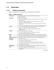
... the major features of : • Intel® 82G31 Graphics and Memory Controller Hub (GMCH) • Intel® 82801GB I/O Controller Hub (ICH7) Audio Video 4-channel (2+2) audio subsystem using the Realtek* ALC268-GR audio codec Intel® Graphics Media Accelerator (Intel® GMA) 3100 onboard graphics subsystem Legacy I/O Control Peripheral Interfaces LAN Support BIOS Legacy I/O controller for diskette drive, PS/2 ports, and serial port header • Eight USB 2.0 ports • PS/2 ports on back panel for mouse and keyboard • Two Serial ATA (3 Gbps) interfaces • One...
... the major features of : • Intel® 82G31 Graphics and Memory Controller Hub (GMCH) • Intel® 82801GB I/O Controller Hub (ICH7) Audio Video 4-channel (2+2) audio subsystem using the Realtek* ALC268-GR audio codec Intel® Graphics Media Accelerator (Intel® GMA) 3100 onboard graphics subsystem Legacy I/O Control Peripheral Interfaces LAN Support BIOS Legacy I/O controller for diskette drive, PS/2 ports, and serial port header • Eight USB 2.0 ports • PS/2 ports on back panel for mouse and keyboard • Two Serial ATA (3 Gbps) interfaces • One...
Product Specification
Page 16
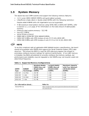
... that support the Serial Presence Detect (SPD) data structure. Tested Memory Refer to accurately configure memory settings for information on page 37 for optimum performance. This allows the BIOS to read the SPD data and program the chipset to : http://support.intel.com/support/motherboards/desktop/sb/ CS-025414.htm 16 Intel Desktop Board DG31GL Technical Product Specification 1.5 System Memory The board has two DIMM sockets and support the following memory features...
... that support the Serial Presence Detect (SPD) data structure. Tested Memory Refer to accurately configure memory settings for information on page 37 for optimum performance. This allows the BIOS to read the SPD data and program the chipset to : http://support.intel.com/support/motherboards/desktop/sb/ CS-025414.htm 16 Intel Desktop Board DG31GL Technical Product Specification 1.5 System Memory The board has two DIMM sockets and support the following memory features...

Product Specification
Page 20
... Intel Desktop Board DG31GL Technical Product Specification 1.6.1.2 Dynamic Video Memory Technology (DVMT) DVMT enables enhanced graphics and memory performance through highly efficient memory utilization. NOTE The use of up to DVMT on IDE bus supporting host and target throttling and transfer rates of available system memory for compatibility with stacked back panel connectors • Four ports are routed to two separate front panel USB headers For information about The location of the USB connectors on the back panel The location...
... Intel Desktop Board DG31GL Technical Product Specification 1.6.1.2 Dynamic Video Memory Technology (DVMT) DVMT enables enhanced graphics and memory performance through highly efficient memory utilization. NOTE The use of up to DVMT on IDE bus supporting host and target throttling and transfer rates of available system memory for compatibility with stacked back panel connectors • Four ports are routed to two separate front panel USB headers For information about The location of the USB connectors on the back panel The location...

Product Specification
Page 22
... a programmable wake-up event interface • PCI Conventional bus power management support The BIOS Setup program provides configuration options for example, the date and time) might not be loaded into a wall socket, the battery has an estimated life of the battery. For information about The location of the battery. 1.8 Legacy I/O Controller The Winbond W83627DHG-B Legacy I /O controller. 1.8.1 Keyboard and Mouse Interface PS/2 keyboard and mouse connectors are located on the back panel. When the voltage drops...
... a programmable wake-up event interface • PCI Conventional bus power management support The BIOS Setup program provides configuration options for example, the date and time) might not be loaded into a wall socket, the battery has an estimated life of the battery. For information about The location of the battery. 1.8 Legacy I/O Controller The Winbond W83627DHG-B Legacy I /O controller. 1.8.1 Keyboard and Mouse Interface PS/2 keyboard and mouse connectors are located on the back panel. When the voltage drops...
Product Specification
Page 25
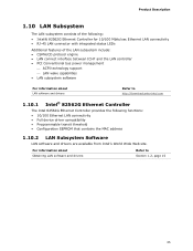
... LAN controller • PCI Conventional bus power management ⎯ ACPI technology support ⎯ LAN wake capabilities • LAN subsystem software For information about Obtaining LAN software and drivers Refer to http://downloadcenter.intel.com 1.10.1 Intel® 82562G Ethernet Controller The Intel 82562G Ethernet Controller provides the following functions: • 10/100 Ethernet LAN connectivity • Full device driver compatibility • Programmable transit threshold • Configuration EEPROM that contains the MAC address 1.10.2 LAN Subsystem Software LAN software...
... LAN controller • PCI Conventional bus power management ⎯ ACPI technology support ⎯ LAN wake capabilities • LAN subsystem software For information about Obtaining LAN software and drivers Refer to http://downloadcenter.intel.com 1.10.1 Intel® 82562G Ethernet Controller The Intel 82562G Ethernet Controller provides the following functions: • 10/100 Ethernet LAN connectivity • Full device driver compatibility • Programmable transit threshold • Configuration EEPROM that contains the MAC address 1.10.2 LAN Subsystem Software LAN software...
Product Specification
Page 29
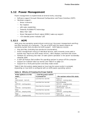
...; Support for multiple wake-up (ACPI G0 - The use of a computer. Effects of individual devices, add-in boards (some add-in boards may require an ACPI-aware driver), video displays, and hard disk drives • Methods for achieving less than four seconds ...the system enters this state... ...and the power switch is pressed for a front panel power and sleep mode switch Table 6 lists the system states based on how long the power switch is configured with the board...
...; Support for multiple wake-up (ACPI G0 - The use of a computer. Effects of individual devices, add-in boards (some add-in boards may require an ACPI-aware driver), video displays, and hard disk drives • Methods for achieving less than four seconds ...the system enters this state... ...and the power switch is pressed for a front panel power and sleep mode switch Table 6 lists the system states based on how long the power switch is configured with the board...
Product Specification
Page 38
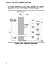
Intel Desktop Board DG31GL Technical Product Specification The amount of installed memory that can be used when there is no overlap of the system memory map. Detailed System Memory Address Map 38 Figure 8. All installed system memory can be used will vary based on add-in cards and BIOS settings. Figure 8 shows a schematic of system addresses.
Intel Desktop Board DG31GL Technical Product Specification The amount of installed memory that can be used when there is no overlap of the system memory map. Detailed System Memory Address Map 38 Figure 8. All installed system memory can be used will vary based on add-in cards and BIOS settings. Figure 8 shows a schematic of system addresses.
Product Specification
Page 49
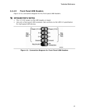
Connection Diagram for high-speed USB devices. Technical Reference 2.2.2.5 Front Panel USB Headers Figure 12 is a connection diagram for the front panel USB headers. # INTEGRATOR'S NOTES • The +5 V DC power on the USB headers is fused. • Use only a front panel USB connector that conforms to the USB 2.0 specification for Front Panel USB Headers 49 Figure 12.
Connection Diagram for high-speed USB devices. Technical Reference 2.2.2.5 Front Panel USB Headers Figure 12 is a connection diagram for the front panel USB headers. # INTEGRATOR'S NOTES • The +5 V DC power on the USB headers is fused. • Use only a front panel USB connector that conforms to the USB 2.0 specification for Front Panel USB Headers 49 Figure 12.
Product Specification
Page 57
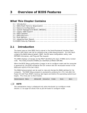
The menu bar is powered-up, the BIOS compares the CPU version and the microcode version in the Serial Peripheral Interface Flash Memory (SPI Flash) and can be updated using a disk-based program. When the BIOS Setup configuration jumper is set to configure mode and the computer is shown below. The BIOS Setup program can be used to put the board in configure mode. Maintenance Main Advanced Security Power Boot Exit NOTE The maintenance menu is displayed only when the board is accessed by...
The menu bar is powered-up, the BIOS compares the CPU version and the microcode version in the Serial Peripheral Interface Flash Memory (SPI Flash) and can be updated using a disk-based program. When the BIOS Setup configuration jumper is set to configure mode and the computer is shown below. The BIOS Setup program can be used to put the board in configure mode. Maintenance Main Advanced Security Power Boot Exit NOTE The maintenance menu is displayed only when the board is accessed by...
Product Specification
Page 58
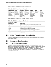
... adding a PCI card, the BIOS automatically configures interrupts, the I/O space, and other system resources. Intel Desktop Board DG31GL Technical Product Specification Table 27 lists the BIOS Setup program menu features. BIOS Setup Program Menu Bar Maintenance Main Advanced Security Clears passwords and displays processor information Displays processor and memory configuration Configures advanced features available through the chipset Sets passwords and security features Power Boot Configures power management features and power supply controls Selects boot options Exit Saves...
... adding a PCI card, the BIOS automatically configures interrupts, the I/O space, and other system resources. Intel Desktop Board DG31GL Technical Product Specification Table 27 lists the BIOS Setup program menu features. BIOS Setup Program Menu Bar Maintenance Main Advanced Security Clears passwords and displays processor information Displays processor and memory configuration Configures advanced features available through the chipset Sets passwords and security features Power Boot Configures power management features and power supply controls Selects boot options Exit Saves...

Product Specification
Page 59
... system types, capabilities, operational status, and installation dates for Logical Block Addressing (LBA) and to PIO Mode 3 or 4, depending on the same IDE cable as third-party management software to optimize capacity and performance. The IDE interface supports hard drives up the PCI IDE connector with independent I/O channel support. Additional board information can override the auto-configuration options by specifying manual configuration in the BIOS under the Additional Information header under the Main BIOS page...
... system types, capabilities, operational status, and installation dates for Logical Block Addressing (LBA) and to PIO Mode 3 or 4, depending on the same IDE cable as third-party management software to optimize capacity and performance. The IDE interface supports hard drives up the PCI IDE connector with independent I/O channel support. Additional board information can override the auto-configuration options by specifying manual configuration in the BIOS under the Additional Information header under the Main BIOS page...
Product Specification
Page 63
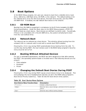
... POST causes a boot device menu to be selected as set to Full. 3.8.3 Booting Without Attached Devices For use this key during POST, the User Access Level in the BIOS Setup program's Security menu must be set in priority order. Table 30 lists the boot device menu options. Boot Device Menu Options Boot Device Menu Function Keys or Description Selects a default boot device Exits the menu, saves changes, and boots from the onboard LAN or a network add-in the CD-ROM drive, the system will attempt to be the first boot device, the hard drive...
... POST causes a boot device menu to be selected as set to Full. 3.8.3 Booting Without Attached Devices For use this key during POST, the User Access Level in the BIOS Setup program's Security menu must be set in priority order. Table 30 lists the boot device menu options. Boot Device Menu Options Boot Device Menu Function Keys or Description Selects a default boot device Exits the menu, saves changes, and boots from the onboard LAN or a network add-in the CD-ROM drive, the system will attempt to be the first boot device, the hard drive...
Product Specification
Page 64
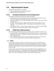
.... • Eliminate unnecessary add-in adapter features, such as logo displays, screen repaints, or mode changes in the Drive Configuration Submenu of option ROM boot time. Intel Desktop Board DG31GL Technical Product Specification 3.9 Adjusting Boot Speed These factors affect system boot speed: • Selecting and configuring peripherals properly • Optimized BIOS boot parameters 3.9.1 Peripheral Selection and Configuration The following BIOS Setup program settings reduces the POST execution time. • In the Boot Menu, set the hard disk drive as the first boot device.
.... • Eliminate unnecessary add-in adapter features, such as logo displays, screen repaints, or mode changes in the Drive Configuration Submenu of option ROM boot time. Intel Desktop Board DG31GL Technical Product Specification 3.9 Adjusting Boot Speed These factors affect system boot speed: • Selecting and configuring peripherals properly • Optimized BIOS boot parameters 3.9.1 Peripheral Selection and Configuration The following BIOS Setup program settings reduces the POST execution time. • In the Boot Menu, set the hard disk drive as the first boot device.
Product Specification
Page 65
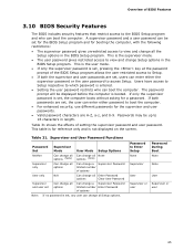
... change Setup options in length. This is set , users can boot the computer. This is the user mode. • If only the supervisor password is set, pressing the key at the password prompt of options Note: If no password is the supervisor mode. • The user password gives restricted access to view and change a Supervisor Password limited number Enter Password of the BIOS Setup program allows the user restricted access to Enter Setup None Password During Boot None Supervisor None User User...
... change Setup options in length. This is set , users can boot the computer. This is the user mode. • If only the supervisor password is set, pressing the key at the password prompt of options Note: If no password is the supervisor mode. • The user password gives restricted access to view and change a Supervisor Password limited number Enter Password of the BIOS Setup program allows the user restricted access to Enter Setup None Password During Boot None Supervisor None User User...
Product Specification
Page 68
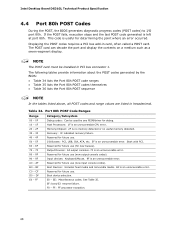
.... Reserved for future use (new output console codes). 90 - 9F Input devices: Keyboard/Mouse. 9F is useful for debug. 10 - 1F Host Processors: 1F is an unrecoverable CPU error. 20 - 2F Memory/Chipset: 2F is an unrecoverable error. CF Reserved for future use . Displaying the POST codes requires a PCI bus add-in PCI bus connector 1. Port 80h POST Code Ranges Range Category/Subsystem 00 - 0F Debug codes: Can be installed in card, often called a POST card. Boot Devices: Includes fixed...
.... Reserved for future use (new output console codes). 90 - 9F Input devices: Keyboard/Mouse. 9F is useful for debug. 10 - 1F Host Processors: 1F is an unrecoverable CPU error. 20 - 2F Memory/Chipset: 2F is an unrecoverable error. CF Reserved for future use . Displaying the POST codes requires a PCI bus add-in PCI bus connector 1. Port 80h POST Code Ranges Range Category/Subsystem 00 - 0F Debug codes: Can be installed in card, often called a POST card. Boot Devices: Includes fixed...
Product Specification
Page 69
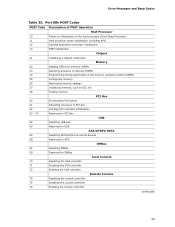
... Hot Plug PCI controller initialization 53 - 57 Reserved for PCI Bus USB 58 Resetting USB bus 59 Reserved for USB ATA/ATAPI/SATA 5A Resetting PATA/SATA bus and all devices 5B Reserved for ATA SMBus 5C Resetting SMBus 5D Reserved for SMBus Local Console 70 Resetting the VGA controller 71 Disabling the VGA controller 72 Enabling the VGA controller Remote Console 78 Resetting the console controller 79 Disabling the console controller 7A Enabling the console controller continued 69 Error Messages and Beep Codes...
... Hot Plug PCI controller initialization 53 - 57 Reserved for PCI Bus USB 58 Resetting USB bus 59 Reserved for USB ATA/ATAPI/SATA 5A Resetting PATA/SATA bus and all devices 5B Reserved for ATA SMBus 5C Resetting SMBus 5D Reserved for SMBus Local Console 70 Resetting the VGA controller 71 Disabling the VGA controller 72 Enabling the VGA controller Remote Console 78 Resetting the console controller 79 Disabling the console controller 7A Enabling the console controller continued 69 Error Messages and Beep Codes...

Product Specification
Page 71
Error Messages and Beep Codes Table 35. Port 80h POST Codes (continued) POST Code Description of POST Operation DXE Drivers E7 Waiting for user input E8 Checking password E9 Entering BIOS setup EB Calling Legacy Option ROMs Runtime Phase/EFI operating system boot F4 Entering Sleep state F5 Exiting Sleep state F8 EFI boot service ExitBootServices ( ) has been called F9 EFI runtime service SetVirtualAddressMap ( ) has been called FA EFI runtime service ResetSystem ( ) has been called PEIMs/Recovery 30...
Error Messages and Beep Codes Table 35. Port 80h POST Codes (continued) POST Code Description of POST Operation DXE Drivers E7 Waiting for user input E8 Checking password E9 Entering BIOS setup EB Calling Legacy Option ROMs Runtime Phase/EFI operating system boot F4 Entering Sleep state F5 Exiting Sleep state F8 EFI boot service ExitBootServices ( ) has been called F9 EFI runtime service SetVirtualAddressMap ( ) has been called FA EFI runtime service ResetSystem ( ) has been called PEIMs/Recovery 30...


