
Product Specification
Page 2
... obtain the latest specifications before being incorporated into a revision of any features or instructions marked "reserved" or "undefined." Copyright © 2010, Intel Corporation. Changes to deviate from : Intel Corporation P.O. Intel® desktop boards may contain design defects or errors known as the property of documents and other Intel literature, may make changes to only the standard Intel® Desktop Board DG41BI with BIOS identifier BIG4110H...
... obtain the latest specifications before being incorporated into a revision of any features or instructions marked "reserved" or "undefined." Copyright © 2010, Intel Corporation. Changes to deviate from : Intel Corporation P.O. Intel® desktop boards may contain design defects or errors known as the property of documents and other Intel literature, may make changes to only the standard Intel® Desktop Board DG41BI with BIOS identifier BIG4110H...

Product Specification
Page 3
... hardware used on the board Technical reference for Intel® Desktop Board DG41BI. CAUTION Cautions are used in all specifications of these symbols and abbreviations appear in this type. iii Preface This Technical Product Specification (TPS) specifies the board layout, components, connectors, and power and environmental requirements for the board Regulatory compliance and battery disposal information Typographical Conventions This section contains information about the Intel Desktop Board DG41BI...
... hardware used on the board Technical reference for Intel® Desktop Board DG41BI. CAUTION Cautions are used in all specifications of these symbols and abbreviations appear in this type. iii Preface This Technical Product Specification (TPS) specifies the board layout, components, connectors, and power and environmental requirements for the board Regulatory compliance and battery disposal information Typographical Conventions This section contains information about the Intel Desktop Board DG41BI...

Product Specification
Page 5
... Connectors 18 5. Jumpers 17 4. Major Board Components 9 2. Board Dimensions 19 v Contents 1 Product Description 1.1 Overview 7 1.1.1 Feature Summary 7 1.1.2 Board Layout 9 1.2 Online Support/Information 11 2 Technical Reference 2.1 Connectors, Headers, and Jumpers 13 2.1.1 Component-side Headers and Connectors 13 2.1.2 Component-side Jumpers 17 2.1.3 Back Panel Connectors 18 2.2 Mechanical Considerations 19 2.2.1 Form Factor 19 2.3 Electrical Considerations 20 2.3.1 Power Supply Considerations 20 2.4 Thermal Considerations 20 2.5 Reliability 21 2.6 ACPI Wake-up Devices...
... Connectors 18 5. Jumpers 17 4. Major Board Components 9 2. Board Dimensions 19 v Contents 1 Product Description 1.1 Overview 7 1.1.1 Feature Summary 7 1.1.2 Board Layout 9 1.2 Online Support/Information 11 2 Technical Reference 2.1 Connectors, Headers, and Jumpers 13 2.1.1 Component-side Headers and Connectors 13 2.1.2 Component-side Jumpers 17 2.1.3 Back Panel Connectors 18 2.2 Mechanical Considerations 19 2.2.1 Form Factor 19 2.3 Electrical Considerations 20 2.3.1 Power Supply Considerations 20 2.4 Thermal Considerations 20 2.5 Reliability 21 2.6 ACPI Wake-up Devices...

Product Specification
Page 6
... Connector 15 9. Clear Password Jumper Settings 17 15. Connectors and Headers Shown in Figure 1 10 3. Chassis Fan Header 14 6. Product Certification Markings 30 vi Front Panel Audio Header 15 8. Front Panel Header 15 11. Front Panel USB1/USB2 Header 16 12. Recommended Power Supply Current Values 20 16. EMC Regulations 27 20. Thermal Considerations for Components 21 17. Safety Standards 23 19. Wireless LAN LED Connector 15 10. Processor Core Power Connector 16 13. Main Power Connector 16 14. Processor Fan Header...
... Connector 15 9. Clear Password Jumper Settings 17 15. Connectors and Headers Shown in Figure 1 10 3. Chassis Fan Header 14 6. Product Certification Markings 30 vi Front Panel Audio Header 15 8. Front Panel Header 15 11. Front Panel USB1/USB2 Header 16 12. Recommended Power Supply Current Values 20 16. EMC Regulations 27 20. Thermal Considerations for Components 21 17. Safety Standards 23 19. Wireless LAN LED Connector 15 10. Processor Core Power Connector 16 13. Main Power Connector 16 14. Processor Fan Header...

Product Specification
Page 7
... Graphics and Memory Controller Hub (GMCH) • Intel® 82801GB I/O Controller Hub (ICH7) Intel® Graphics Media Accelerator X4500 (Intel® GMA X4500) onboard graphics subsystem with VGA output Audio Peripheral Interfaces Six (5.1)-channel audio subsystem using the Realtek* ALC662 audio codec, including: • Back panel audio jacks • Front panel audio header • S/PDIF out header • Eight USB 2.0 ports (four back panel connectors and two front panel headers each providing two USB ports) • Four Serial ATA (SATA) interfaces LAN Support BIOS 10...
... Graphics and Memory Controller Hub (GMCH) • Intel® 82801GB I/O Controller Hub (ICH7) Intel® Graphics Media Accelerator X4500 (Intel® GMA X4500) onboard graphics subsystem with VGA output Audio Peripheral Interfaces Six (5.1)-channel audio subsystem using the Realtek* ALC662 audio codec, including: • Back panel audio jacks • Front panel audio header • S/PDIF out header • Eight USB 2.0 ports (four back panel connectors and two front panel headers each providing two USB ports) • Four Serial ATA (SATA) interfaces LAN Support BIOS 10...

Product Specification
Page 8
... RAM support • Wake on PCI, front panel, PCI Express, LAN, and USB ports • One PCI Express x16 bus add-in card connector • Two PCI Express x1 add-in card connectors • One PCI Express Mini Card connector • One Conventional PCI bus connector Hardware Monitor Subsystem • Voltage sense to detect out of range power supply voltages • Thermal sense to detect out of range thermal values • Two fan headers • Two fan sense inputs used to monitor fan activity 8 Intel Desktop Board DG41BI Technical Product Specification...
... RAM support • Wake on PCI, front panel, PCI Express, LAN, and USB ports • One PCI Express x16 bus add-in card connector • Two PCI Express x1 add-in card connectors • One PCI Express Mini Card connector • One Conventional PCI bus connector Hardware Monitor Subsystem • Voltage sense to detect out of range power supply voltages • Thermal sense to detect out of range thermal values • Two fan headers • Two fan sense inputs used to monitor fan activity 8 Intel Desktop Board DG41BI Technical Product Specification...

Product Specification
Page 11
... information about... Intel Desktop Board DG41BI Desktop Board Support Available configurations for the Intel Desktop Board DG41BI Supported processors Chipset information BIOS and driver updates Tested Memory Visit this World Wide Web site: http://www.intel.com/products/motherboard/DG41BI/index.htm http://www.intel.com/support/motherboards/desktop http://www.intel.com/products/motherboard/DG41BI/index.htm http://processormatch.intel.com http://www.intel.com/products/desktop/chipsets/index.htm http://downloadcenter.intel.com http://support.intel.com/support/motherboards/desktop/sb/CS025414...
... information about... Intel Desktop Board DG41BI Desktop Board Support Available configurations for the Intel Desktop Board DG41BI Supported processors Chipset information BIOS and driver updates Tested Memory Visit this World Wide Web site: http://www.intel.com/products/motherboard/DG41BI/index.htm http://www.intel.com/support/motherboards/desktop http://www.intel.com/products/motherboard/DG41BI/index.htm http://processormatch.intel.com http://www.intel.com/products/desktop/chipsets/index.htm http://downloadcenter.intel.com http://support.intel.com/support/motherboards/desktop/sb/CS025414...

Product Specification
Page 13
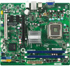
Component-side Connectors and Headers 13 Figure 2. 2 Technical Reference 2.1 Connectors, Headers, and Jumpers This section describes the board's connectors, headers, and jumpers. 2.1.1 Component-side Headers and Connectors Figure 2 shows the location of the board's component-side headers and connectors.
Component-side Connectors and Headers 13 Figure 2. 2 Technical Reference 2.1 Connectors, Headers, and Jumpers This section describes the board's connectors, headers, and jumpers. 2.1.1 Component-side Headers and Connectors Figure 2 shows the location of the board's component-side headers and connectors.

Product Specification
Page 14
Intel Desktop Board DG41BI Technical Product Specification Table 3 lists the connectors and headers identified in card connector B PCI Express x1 connector C PCI Express x1 connector D PCI Express x16 connector E Processor core power connector (2 X 2) F Chassis fan header G Processor fan header H Main power connector (2 X 12) I Front panel header J Serial ATA connectors K Front panel USB header L Front panel USB header M Wireless LAN LED connector N S/PDIF connector O Front panel audio header Table 4 though Table 13 list the signal names for the component-side ...
Intel Desktop Board DG41BI Technical Product Specification Table 3 lists the connectors and headers identified in card connector B PCI Express x1 connector C PCI Express x1 connector D PCI Express x16 connector E Processor core power connector (2 X 2) F Chassis fan header G Processor fan header H Main power connector (2 X 12) I Front panel header J Serial ATA connectors K Front panel USB header L Front panel USB header M Wireless LAN LED connector N S/PDIF connector O Front panel audio header Table 4 though Table 13 list the signal names for the component-side ...

Product Specification
Page 15
... Table 8. S/PDIF Out Connector Pin Signal Name 1 +5V 2 SPDIF_O2_L 3 Ground Table 9. Processor Fan Header Pin Signal Name 1 Ground 2 +12 V 3 CFAN_D 4 CPUFAN_PWM_C Table 7. Front Panel Header Pin Signal Name Pin 1 HDLED+ 2 3 HDLED- 4 5 Ground 6 7 FP_SYS_RST# 8 9 FPA_DET# 10 Signal Name AGND F_AUDIO_DET# MIC_JD KEY (no pin) LIN_JD Signal Name FP_LED+ FP_LEDFP_PWRBTN# Ground Key (no pin) 15 Technical Reference Table 6. Wireless LAN LED Connector Pin Signal Name 1 No connector 2 No connector 3 +5V 4 LED_WLAN# 5 Ground...
... Table 8. S/PDIF Out Connector Pin Signal Name 1 +5V 2 SPDIF_O2_L 3 Ground Table 9. Processor Fan Header Pin Signal Name 1 Ground 2 +12 V 3 CFAN_D 4 CPUFAN_PWM_C Table 7. Front Panel Header Pin Signal Name Pin 1 HDLED+ 2 3 HDLED- 4 5 Ground 6 7 FP_SYS_RST# 8 9 FPA_DET# 10 Signal Name AGND F_AUDIO_DET# MIC_JD KEY (no pin) LIN_JD Signal Name FP_LED+ FP_LEDFP_PWRBTN# Ground Key (no pin) 15 Technical Reference Table 6. Wireless LAN LED Connector Pin Signal Name 1 No connector 2 No connector 3 +5V 4 LED_WLAN# 5 Ground...

Product Specification
Page 16
Processor Core Power Connector Pin Signal Name Pin 1 Ground 2 3 +12 V 4 Table 13. Intel Desktop Board DG41BI Technical Product Specification Table 11. Front Panel USB1/USB2 Header Pin Signal Name Pin 1 +5V_Dual 2 3 D1- 4 5 D1+ 6 7 Ground 8 9 Key (no pin) Signal Name Ground +12 V Signal Name +3.3 V -12 V Ground PS-ON# (power supply remote on/off) Ground Ground Ground No connect +5 V +5 V +5 V Ground 16 Main Power Connector Pin Signal Name Pin 1 +3.3 V 13 2 +3.3 V 14 3 Ground 15 4 +5 V 16 5 Ground 17 6 +5 V 18 7 Ground...
Processor Core Power Connector Pin Signal Name Pin 1 Ground 2 3 +12 V 4 Table 13. Intel Desktop Board DG41BI Technical Product Specification Table 11. Front Panel USB1/USB2 Header Pin Signal Name Pin 1 +5V_Dual 2 3 D1- 4 5 D1+ 6 7 Ground 8 9 Key (no pin) Signal Name Ground +12 V Signal Name +3.3 V -12 V Ground PS-ON# (power supply remote on/off) Ground Ground Ground No connect +5 V +5 V +5 V Ground 16 Main Power Connector Pin Signal Name Pin 1 +3.3 V 13 2 +3.3 V 14 3 Ground 15 4 +5 V 16 5 Ground 17 6 +5 V 18 7 Ground...

Product Specification
Page 17
Table 14. Clear Password Jumper Settings Function/Mode Reserved Jumper Setting 2-4 Configuration Reserved Normal (default) 4-6 Normal operation Clear Password 1-3 Normal (default) 3-5 Clears the current password Current password (if set) is in Figure 3, A. Technical Reference 2.1.2 Component-side Jumpers Figure 3 shows the location of the board's jumper block. Figure 3. Jumpers Table 14 show the settings for the Clear Password jumper block identified in effect 17
Table 14. Clear Password Jumper Settings Function/Mode Reserved Jumper Setting 2-4 Configuration Reserved Normal (default) 4-6 Normal operation Clear Password 1-3 Normal (default) 3-5 Clears the current password Current password (if set) is in Figure 3, A. Technical Reference 2.1.2 Component-side Jumpers Figure 3 shows the location of the board's jumper block. Figure 3. Jumpers Table 14 show the settings for the Clear Password jumper block identified in effect 17

Product Specification
Page 18
Item A B C D E F G Description VGA USB 2.0 (2) LAN USB 2.0 (2) Line in Line out Mic Figure 4. Back Panel Connectors 18 Intel Desktop Board DG41BI Technical Product Specification 2.1.3 Back Panel Connectors Figure 4 shows the locations of the back panel connectors.
Item A B C D E F G Description VGA USB 2.0 (2) LAN USB 2.0 (2) Line in Line out Mic Figure 4. Back Panel Connectors 18 Intel Desktop Board DG41BI Technical Product Specification 2.1.3 Back Panel Connectors Figure 4 shows the locations of the back panel connectors.

Product Specification
Page 20
... do so can reach a temperature of a supported 65 W processor, 1 GB DDR3 RAM, one hard disk drive, one optical drive, and all board peripherals enabled, the minimum recommended power supply is maintained in a system with the reader. Failure to do so may result in damage to 95 oC in this document will depend on the wake devices supported and manufacturing options. Recommended Power Supply Current Values Output Voltage 3.3 V 5 V 12 V1 12...
... do so can reach a temperature of a supported 65 W processor, 1 GB DDR3 RAM, one hard disk drive, one optical drive, and all board peripherals enabled, the minimum recommended power supply is maintained in a system with the reader. Failure to do so may result in damage to 95 oC in this document will depend on the wake devices supported and manufacturing options. Recommended Power Supply Current Values Output Voltage 3.3 V 5 V 12 V1 12...

Product Specification
Page 21
... Procedure, TR-NWT-000332, Issue 4, September 1991. Maximum case temperatures are sensitive to thermal changes. LAN PME# signal Power switch RTC alarm USB WAKE# signal ...from specific states. The calculation is calculated from predicted data at 55 ºC. Intel Desktop Board DG41BI MTBF is 197,677 hours. 2.6 ACPI Wake-up Devices and Events Table 17 lists the devices or specific events that are important when considering proper airflow...
... Procedure, TR-NWT-000332, Issue 4, September 1991. Maximum case temperatures are sensitive to thermal changes. LAN PME# signal Power switch RTC alarm USB WAKE# signal ...from specific states. The calculation is calculated from predicted data at 55 ºC. Intel Desktop Board DG41BI MTBF is 197,677 hours. 2.6 ACPI Wake-up Devices and Events Table 17 lists the devices or specific events that are important when considering proper airflow...

Product Specification
Page 23
... • European Union Declaration of Conformity statement • Product Ecology statements • Electromagnetic Compatibility (EMC) standards • Product certification markings 3.1.1 Safety Standards The Intel Desktop Board DG41BI complies with the safety standards stated in Table 18 when correctly installed in a compatible host system. Safety Standards Standard Title CSA/UL 60950-1 Information Technology Equipment - Safety - Part 1: General Requirements (International) 23
... • European Union Declaration of Conformity statement • Product Ecology statements • Electromagnetic Compatibility (EMC) standards • Product certification markings 3.1.1 Safety Standards The Intel Desktop Board DG41BI complies with the safety standards stated in Table 18 when correctly installed in a compatible host system. Safety Standards Standard Title CSA/UL 60950-1 Information Technology Equipment - Safety - Part 1: General Requirements (International) 23

Product Specification
Page 27
... The Intel Desktop Board DG41BI complies with the EMC regulations stated in Table 19 when correctly installed in a compatible host system. Immunity Characteristics Limits and methods of Information Technology Equipment. (International) CISPR 24 Information Technology Equipment - EMC Regulations Regulation Title FCC 47 CFR Part 15, Subpart B ICES-003 Title 47 of the Code of Federal Regulations, Part 15, Subpart B, Radio Frequency Devices. (USA...
... The Intel Desktop Board DG41BI complies with the EMC regulations stated in Table 19 when correctly installed in a compatible host system. Immunity Characteristics Limits and methods of Information Technology Equipment. (International) CISPR 24 Information Technology Equipment - EMC Regulations Regulation Title FCC 47 CFR Part 15, Subpart B ICES-003 Title 47 of the Code of Federal Regulations, Part 15, Subpart B, Radio Frequency Devices. (USA...

Product Specification
Page 28
... to comply with the instructions, may cause harmful interference to provide reasonable protection against harmful interference in a residential installation. For questions related to comply with Part 15 of the FCC Rules. Intel Desktop Board DG41BI Technical Product Specification FCC Declaration of Conformity This device complies with FCC standards for radio noise emissions from digital apparatus set out in the...
... to comply with the instructions, may cause harmful interference to provide reasonable protection against harmful interference in a residential installation. For questions related to comply with Part 15 of the FCC Rules. Intel Desktop Board DG41BI Technical Product Specification FCC Declaration of Conformity This device complies with FCC standards for radio noise emissions from digital apparatus set out in the...
Product Specification
Page 29
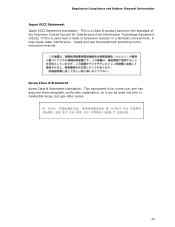
...Install and use , and has acquired electromagnetic conformity registration, so it can be used near a radio or television receiver in residential areas, but also other areas. 29 If this is a Class B product based on the standard of the Voluntary Control Council for home use the equipment according to the instruction manual. Regulatory Compliance and Battery... Disposal Information Japan VCCI Statement Japan VCCI Statement translation: This is used not only in ...
...Install and use , and has acquired electromagnetic conformity registration, so it can be used near a radio or television receiver in residential areas, but also other areas. 29 If this is a Class B product based on the standard of the Voluntary Control Council for home use the equipment according to the instruction manual. Regulatory Compliance and Battery... Disposal Information Japan VCCI Statement Japan VCCI Statement translation: This is used not only in ...

Product Specification
Page 30
... compliance to be 10 years. 30 Includes adjacent Intel supplier code number, N-232. Japan VCCI (Voluntary Control Council for Intel Desktop Boards: E210882. Taiwan BSMI (Bureau of the symbol used on Intel Desktop Boards and associated collateral. Printed wiring board manufacturer's recognition mark. KCC (Korean Communications Commission) EMC certification mark. China RoHS/Environmentally Friendly Use Period Logo: This is an example of Standards...
... compliance to be 10 years. 30 Includes adjacent Intel supplier code number, N-232. Japan VCCI (Voluntary Control Council for Intel Desktop Boards: E210882. Taiwan BSMI (Bureau of the symbol used on Intel Desktop Boards and associated collateral. Printed wiring board manufacturer's recognition mark. KCC (Korean Communications Commission) EMC certification mark. China RoHS/Environmentally Friendly Use Period Logo: This is an example of Standards...


