
Product Guide
Page 3
... this manual: CAUTION Cautions warn the user about how to prevent damage to important information. may not be supported without further evaluation by Intel. NOTE Notes call attention to hardware or loss of product features 2 Installing and Replacing Desktop Board Components: instructions on how to update the BIOS A Error Messages and Indicators: information about board layout, component installation, BIOS update, and regulatory requirements for installation in this Product Guide...
... this manual: CAUTION Cautions warn the user about how to prevent damage to important information. may not be supported without further evaluation by Intel. NOTE Notes call attention to hardware or loss of product features 2 Installing and Replacing Desktop Board Components: instructions on how to update the BIOS A Error Messages and Indicators: information about board layout, component installation, BIOS update, and regulatory requirements for installation in this Product Guide...

Product Guide
Page 5
... Chipset 14 Main Memory...15 Graphics Subsystem 15 Integrated Graphics 15 Analog Display (VGA 15 High-Definition Multimedia Interface* (HDMI 16 Digital Visual Interface (DVI-D 16 PCI Express* x16 Graphics 16 Audio Subsystem 17 LAN Subsystem 17 USB 2.0 Support 18 Serial ATA Support 18 Expandability...19 Legacy I/O ...19 BIOS ...19 Serial ATA Auto Configuration 19 PCI*/PCI Express Auto Configuration 19 Security Passwords 20 Hardware Management 20 Hardware Monitoring and Fan Speed Control 20 Fan Monitoring 20 Chassis Intrusion 21 Power Management 21 Software Support 21 ACPI...
... Chipset 14 Main Memory...15 Graphics Subsystem 15 Integrated Graphics 15 Analog Display (VGA 15 High-Definition Multimedia Interface* (HDMI 16 Digital Visual Interface (DVI-D 16 PCI Express* x16 Graphics 16 Audio Subsystem 17 LAN Subsystem 17 USB 2.0 Support 18 Serial ATA Support 18 Expandability...19 Legacy I/O ...19 BIOS ...19 Serial ATA Auto Configuration 19 PCI*/PCI Express Auto Configuration 19 Security Passwords 20 Hardware Management 20 Hardware Monitoring and Fan Speed Control 20 Fan Monitoring 20 Chassis Intrusion 21 Power Management 21 Software Support 21 ACPI...

Product Guide
Page 6
...a PCI Express x16 Graphics Card 41 Removing a PCI Express x16 Graphics Card 42 Connecting Serial ATA (SATA) Cables 44 Installing an Intel® Z-U130 USB Solid-State Drive (or Compatible Device 45 Connecting to the Internal Headers 46 Front Panel Audio Header 47 Internal Mono Speaker Header 47 S/PDIF Header 48 Parallel Port Header 48 Chassis Intrusion Header 49 Intel® RPAT Header 49 Alternate Front Panel Power LED Header 49 Front Panel Header 50 Front Panel USB 2.0 Headers 50 Serial Header 51 Connecting to the Audio System 52 Connecting Chassis Fan and Power Supply Cables...
...a PCI Express x16 Graphics Card 41 Removing a PCI Express x16 Graphics Card 42 Connecting Serial ATA (SATA) Cables 44 Installing an Intel® Z-U130 USB Solid-State Drive (or Compatible Device 45 Connecting to the Internal Headers 46 Front Panel Audio Header 47 Internal Mono Speaker Header 47 S/PDIF Header 48 Parallel Port Header 48 Chassis Intrusion Header 49 Intel® RPAT Header 49 Alternate Front Panel Power LED Header 49 Front Panel Header 50 Front Panel USB 2.0 Headers 50 Serial Header 51 Connecting to the Audio System 52 Connecting Chassis Fan and Power Supply Cables...

Product Guide
Page 7
... 17. Installing a PCI Express x16 Graphics Card 42 20. Connecting Power Supply Cables 54 27. Remove the Socket Cover 33 9. Connecting the Processor Fan Heat Sink Power Cable to the Processor Fan Header 36 14. Location of the Chassis Fan Headers 53 26. Lift the Load Plate 32 8. Install the Processor 34 11. Secure the Load Plate in Place 35 13. Example Dual Channel Memory Configuration with Four DIMMs 38 16. LAN Connector LEDs 18 3. Lower the Load Plate 35 12. Back Panel Audio Connectors 52 25. Intel Desktop Board DH55HC...
... 17. Installing a PCI Express x16 Graphics Card 42 20. Connecting Power Supply Cables 54 27. Remove the Socket Cover 33 9. Connecting the Processor Fan Heat Sink Power Cable to the Processor Fan Header 36 14. Location of the Chassis Fan Headers 53 26. Lift the Load Plate 32 8. Install the Processor 34 11. Secure the Load Plate in Place 35 13. Example Dual Channel Memory Configuration with Four DIMMs 38 16. LAN Connector LEDs 18 3. Lower the Load Plate 35 12. Back Panel Audio Connectors 52 25. Intel Desktop Board DH55HC...

Product Guide
Page 8
... Use Period Mark 76 23. Product Certification Markings 80 viii USB 2.0 Header Signal Names 50 14. Chassis Intrusion Header Signal Names 49 10. BIOS Error Messages 68 20. Front Panel Header Signal Names 50 13. Front Panel Audio Header Signal Names for Intel HD Audio 47 5. Intel Desktop Board DH55HC Product Guide Tables 1. Front Panel USB Header (with Intel Z-U130 USB Solid-State Drive (or Compatible Device) Support) Signal Names 51 15. Jumper Settings for the BIOS Setup Program Modes 56 17. Intel Desktop Board...
... Use Period Mark 76 23. Product Certification Markings 80 viii USB 2.0 Header Signal Names 50 14. Chassis Intrusion Header Signal Names 49 10. BIOS Error Messages 68 20. Front Panel Header Signal Names 50 13. Front Panel Audio Header Signal Names for Intel HD Audio 47 5. Intel Desktop Board DH55HC Product Guide Tables 1. Front Panel USB Header (with Intel Z-U130 USB Solid-State Drive (or Compatible Device) Support) Signal Names 51 15. Jumper Settings for the BIOS Setup Program Modes 56 17. Intel Desktop Board...

Product Guide
Page 10
... back panel connector with three dual-port internal headers; Feature Summary (continued) Peripheral Interfaces LAN Support BIOS • Twelve USB 2.0 ports: ― Six ports are implemented with stacked back panel connectors ― Six ports are implemented with integrated status LEDs • Intel® BIOS resident in an SPI Flash device • Support for Advanced Configuration and Power Interface (ACPI), Plug and Play, and SMBIOS Instantly Available PC Technology Hardware Management • Support for PCI Local Bus Specification Revision 2.2 • Support for PCI Express...
... back panel connector with three dual-port internal headers; Feature Summary (continued) Peripheral Interfaces LAN Support BIOS • Twelve USB 2.0 ports: ― Six ports are implemented with stacked back panel connectors ― Six ports are implemented with integrated status LEDs • Intel® BIOS resident in an SPI Flash device • Support for Advanced Configuration and Power Interface (ACPI), Plug and Play, and SMBIOS Instantly Available PC Technology Hardware Management • Support for PCI Local Bus Specification Revision 2.2 • Support for PCI Express...

Product Guide
Page 13
... 1 sockets DDR3 Channel B, DIMM 0 and DIMM 1 sockets Front chassis fan header Main power connector (2 x 12 pin) Chassis intrusion header Intel® Remote PC Assist Technology (Intel® RPAT) header Serial ATA connectors (6) BIOS configuration jumper block Alternate front panel power LED header Front panel header Standby power indicator LED Front panel USB 2.0 headers (2) Front panel USB header with support for an Intel Z-U130 USB Solid-State Drive (or compatible device) Parallel port header Speaker Serial port header S/PDIF header Front panel audio header Internal mono speaker header 13...
... 1 sockets DDR3 Channel B, DIMM 0 and DIMM 1 sockets Front chassis fan header Main power connector (2 x 12 pin) Chassis intrusion header Intel® Remote PC Assist Technology (Intel® RPAT) header Serial ATA connectors (6) BIOS configuration jumper block Alternate front panel power LED header Front panel header Standby power indicator LED Front panel USB 2.0 headers (2) Front panel USB header with support for an Intel Z-U130 USB Solid-State Drive (or compatible device) Parallel port header Speaker Serial port header S/PDIF header Front panel audio header Internal mono speaker header 13...

Product Guide
Page 15
... configure the memory controller for processors with Intel Graphics Technology. Analog Display (VGA) The VGA port supports analog displays. These operating systems will attempt to boot. Integrated Graphics The board supports integrated graphics through the Intel Flexible Display Interface (FDI) for normal operation. Graphics Subsystem The board supports either or both of the HDMI and DVI connector status. 15 The BIOS will report less than 4 GB because of the memory used by add-in either integrated graphics (Intel Graphics Technology) or PCI Express 2.0 x16 graphics...
... configure the memory controller for processors with Intel Graphics Technology. Analog Display (VGA) The VGA port supports analog displays. These operating systems will attempt to boot. Integrated Graphics The board supports integrated graphics through the Intel Flexible Display Interface (FDI) for normal operation. Graphics Subsystem The board supports either or both of the HDMI and DVI connector status. 15 The BIOS will report less than 4 GB because of the memory used by add-in either integrated graphics (Intel Graphics Technology) or PCI Express 2.0 x16 graphics...

Product Guide
Page 17
... LEDs are built into the RJ-45 LAN connector located on the recognized device type. • Stereo input and output via back panel connectors • Headphone and Mic in signals for front panel audio connectors) • S/PDIF audio header (1 x 4 pin header) • Internal mono speaker header (1 x 2 pin header) Front panel headphone output is supported by a separate audio channel pair, allowing multi-streaming audio configurations such as simultaneous 6-channel (5.1) surround sound playback and stereo audio conferencing (through the HDMI interface. The onboard audio headers...
... LEDs are built into the RJ-45 LAN connector located on the recognized device type. • Stereo input and output via back panel connectors • Headphone and Mic in signals for front panel audio connectors) • S/PDIF audio header (1 x 4 pin header) • Internal mono speaker header (1 x 2 pin header) Front panel headphone output is supported by a separate audio channel pair, allowing multi-streaming audio configurations such as simultaneous 6-channel (5.1) surround sound playback and stereo audio conferencing (through the HDMI interface. The onboard audio headers...

Product Guide
Page 19
... compatible with serialized IRQ support for PCI Conventional bus systems • PS/2-style keyboard/mouse interface • Intelligent power management, including a programmable wake-up event interface • PCI Conventional bus power management support The BIOS Setup program provides configuration options for the Legacy I /O space) for your computer, the PCI/PCI Express auto-configuration utility in the BIOS automatically detects and configures the resources (IRQs, DMA channels, and I /O controller. PCI*/PCI Express Auto Configuration If you install a PCI or PCI Express add-in card...
... compatible with serialized IRQ support for PCI Conventional bus systems • PS/2-style keyboard/mouse interface • Intelligent power management, including a programmable wake-up event interface • PCI Conventional bus power management support The BIOS Setup program provides configuration options for the Legacy I /O space) for your computer, the PCI/PCI Express auto-configuration utility in the BIOS automatically detects and configures the resources (IRQs, DMA channels, and I /O controller. PCI*/PCI Express Auto Configuration If you install a PCI or PCI Express add-in card...

Product Guide
Page 21
...; Wake from an AC power failure, the computer returns to the chassis intrusion header on the chassis that provides full ACPI support. When resuming from serial port Software Support ACPI ACPI gives the operating system direct control over the power management and Plug and Play functions of ACPI with the Desktop Board requires an operating system that can be set by using the Last Power State feature in before power was in the BIOS Setup program's Boot menu. Power...
...; Wake from an AC power failure, the computer returns to the chassis intrusion header on the chassis that provides full ACPI support. When resuming from serial port Software Support ACPI ACPI gives the operating system direct control over the power management and Plug and Play functions of ACPI with the Desktop Board requires an operating system that can be set by using the Last Power State feature in before power was in the BIOS Setup program's Boot menu. Power...

Product Guide
Page 22
... technology enables the board to -RAM) sleep-state. The LAN subsystem monitors network traffic and upon detecting a Magic Packet* frame, it asserts a wake-up signal that can adjust the fan speed or switch the fan on or off as configured by a wake-up device or event, the system quickly returns to its last known awake state. 22 When signaled by the BIOS "S3 State Indicator" option). Intel Desktop Board DH55HC Product Guide Fan Headers...
... technology enables the board to -RAM) sleep-state. The LAN subsystem monitors network traffic and upon detecting a Magic Packet* frame, it asserts a wake-up signal that can adjust the fan speed or switch the fan on or off as configured by a wake-up device or event, the system quickly returns to its last known awake state. 22 When signaled by the BIOS "S3 State Indicator" option). Intel Desktop Board DH55HC Product Guide Fan Headers...

Product Guide
Page 25
Desktop Board Features Speaker A speaker is mounted on how to replace the battery. 25 Refer to Appendix A for a description of the battery. Real-Time Clock Subsystem A coin-cell battery (CR2032) powers the real-time clock and CMOS memory. When the battery voltage drops below a certain level, the BIOS Setup program settings stored in , the standby current from the power supply extends the life of the board's beep codes. Go to ± 13 minutes/year...
Desktop Board Features Speaker A speaker is mounted on how to replace the battery. 25 Refer to Appendix A for a description of the battery. Real-Time Clock Subsystem A coin-cell battery (CR2032) powers the real-time clock and CMOS memory. When the battery voltage drops below a certain level, the BIOS Setup program settings stored in , the standby current from the power supply extends the life of the board's beep codes. Go to ± 13 minutes/year...

Product Guide
Page 27
... before you how to: • Install the I/O shield • Install and remove the Desktop Board • Install and remove a processor • Install and remove memory • Install and remove a PCI Express x16 card • Connect Serial ATA cables • Install an Intel Z-U130 USB Solid-State Drive (or Compatible Device) • Connect to the internal headers and connectors • Connect to the audio system • Connect chassis fan and power supply cables • Set the BIOS configuration jumper • Clear passwords • Replace the battery Before You Begin CAUTIONS The...
... before you how to: • Install the I/O shield • Install and remove the Desktop Board • Install and remove a processor • Install and remove memory • Install and remove a PCI Express x16 card • Connect Serial ATA cables • Install an Intel Z-U130 USB Solid-State Drive (or Compatible Device) • Connect to the internal headers and connectors • Connect to the audio system • Connect chassis fan and power supply cables • Set the BIOS configuration jumper • Clear passwords • Replace the battery Before You Begin CAUTIONS The...
Product Guide
Page 40
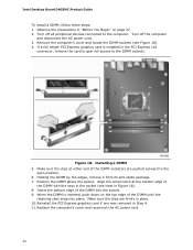
... 18). 4. Reinstall the PCI Express graphics card if one was removed in the PCI Express x16 connector, remove the card to gain full access to the DIMM sockets. If a full length PCI Express graphics card is inserted, push down on page 27. 2. Insert the bottom edge of the DIMM until the retaining clips snap into the socket. 9. Intel Desktop Board DH55HC Product Guide To install a DIMM, follow these steps: 1. Installing a DIMM 5. Make sure...
... 18). 4. Reinstall the PCI Express graphics card if one was removed in the PCI Express x16 connector, remove the card to gain full access to the DIMM sockets. If a full length PCI Express graphics card is inserted, push down on page 27. 2. Insert the bottom edge of the DIMM until the retaining clips snap into the socket. 9. Intel Desktop Board DH55HC Product Guide To install a DIMM, follow these steps: 1. Installing a DIMM 5. Make sure...

Product Guide
Page 41
... length PCI Express graphics card is not fully seated in the PCI Express x16 connector, remove the card to gain access to the DIMMs. 6. If the card is installed in the connector, an electrical short may result across the connector pins. Observe the precautions in "Before You Begin" on the card until it in the PCI Express x16 connector (Figure 19, A) and press down on page 27. 2. Turn off all peripheral devices connected...
... length PCI Express graphics card is not fully seated in the PCI Express x16 connector, remove the card to gain access to the DIMMs. 6. If the card is installed in the connector, an electrical short may result across the connector pins. Observe the precautions in "Before You Begin" on the card until it in the PCI Express x16 connector (Figure 19, A) and press down on page 27. 2. Turn off all peripheral devices connected...
Product Guide
Page 53
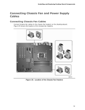
Location of the chassis fan headers. Figure 25 shows the location of the Chassis Fan Headers 53 Figure 25. Installing and Replacing Desktop Board Components Connecting Chassis Fan and Power Supply Cables Connecting Chassis Fan Cables Connect chassis fan cables to the chassis fan headers on the Desktop Board.
Location of the chassis fan headers. Figure 25 shows the location of the Chassis Fan Headers 53 Figure 25. Installing and Replacing Desktop Board Components Connecting Chassis Fan and Power Supply Cables Connecting Chassis Fan Cables Connect chassis fan cables to the chassis fan headers on the Desktop Board.
Product Guide
Page 56
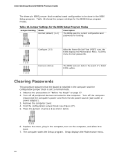
...). 5. Configure (2-3) After the Power-On Self-Test (POST) runs, the BIOS displays the Maintenance Menu. Jumper Settings for the BIOS Setup Program Modes Jumper Setting Mode Normal (default) (1-2) Description The BIOS uses the current configuration and passwords for the BIOS Setup program modes. Clearing Passwords This procedure assumes that the board is set to boot. 7. Disconnect the computer's power cord from the AC power source (wall outlet or power adapter). 3. Remove the computer cover. 4. Replace the cover, plug in the computer, turn on pins 2-3 as...
...). 5. Configure (2-3) After the Power-On Self-Test (POST) runs, the BIOS displays the Maintenance Menu. Jumper Settings for the BIOS Setup Program Modes Jumper Setting Mode Normal (default) (1-2) Description The BIOS uses the current configuration and passwords for the BIOS Setup program modes. Clearing Passwords This procedure assumes that the board is set to boot. 7. Disconnect the computer's power cord from the AC power source (wall outlet or power adapter). 3. Remove the computer cover. 4. Replace the cover, plug in the computer, turn on pins 2-3 as...

Product Guide
Page 57
..., hvis batteriet erstattes med et batteri af en forkert type. Installing and Replacing Desktop Board Components 8. Use the arrow keys to save the current values and exit Setup. 10. The clock is replaced with local environmental regulations. Disposal of the battery. Press and Setup displays a pop-up screen requesting that you confirm clearing the password. Select Yes and press . Replace the cover, plug in CMOS RAM (for example, the date and...
..., hvis batteriet erstattes med et batteri af en forkert type. Installing and Replacing Desktop Board Components 8. Use the arrow keys to save the current values and exit Setup. 10. The clock is replaced with local environmental regulations. Disposal of the battery. Press and Setup displays a pop-up screen requesting that you confirm clearing the password. Select Yes and press . Replace the cover, plug in CMOS RAM (for example, the date and...

Product Guide
Page 63
... hard drive. (You can also save this file to view and change the BIOS settings for multiple identical systems.) 4. Your system will be used to a removable USB device. Go to the DH55HC page, click "Latest BIOS and driver updates," select "BIOS Update [TCIBX10H.86A]," and download the Express BIOS Update utility file. 3. This is included in an automated update utility that combines the functionality of the Intel® Flash Memory Update Utility and the ease of use of Windows-based installation...
... hard drive. (You can also save this file to view and change the BIOS settings for multiple identical systems.) 4. Your system will be used to a removable USB device. Go to the DH55HC page, click "Latest BIOS and driver updates," select "BIOS Update [TCIBX10H.86A]," and download the Express BIOS Update utility file. 3. This is included in an automated update utility that combines the functionality of the Intel® Flash Memory Update Utility and the ease of use of Windows-based installation...


