
Product Guide
Page 3
... 2 Installing and Replacing Desktop Board Components: instructions on how to install the Desktop Board and other environments, such as Information Technology Equipment (I.T.E.) for use in personal computers (PC) for Intel® Desktop Board DH55PJ. The suitability of this product for other PC or embedded non-PC applications or other hardware components 3 Updating the BIOS: instructions on how to update the BIOS A Error Messages and Indicators: information about board layout, component installation, BIOS update, and...
... 2 Installing and Replacing Desktop Board Components: instructions on how to install the Desktop Board and other environments, such as Information Technology Equipment (I.T.E.) for use in personal computers (PC) for Intel® Desktop Board DH55PJ. The suitability of this product for other PC or embedded non-PC applications or other hardware components 3 Updating the BIOS: instructions on how to update the BIOS A Error Messages and Indicators: information about board layout, component installation, BIOS update, and...
Product Guide
Page 5
...Intel® H55 Express Chipset 14 Main Memory...15 Graphics Subsystem 15 Integrated Graphics 15 Analog Display (VGA 15 Digital Visual Interface (DVI-D 16 PCI Express* x16 Graphics 16 Audio Subsystem 16 LAN Subsystem 17 USB 2.0 Support 18 Serial ATA Support 18 Expandability...18 Legacy I/O ...19 BIOS ...19 Serial ATA Auto Configuration 19 PCI*/PCI Express Auto Configuration 19 Security Passwords 20 Hardware Management 20 Hardware Monitoring and Fan Speed Control 20 Fan Monitoring 20 Power Management 21 Software Support 21 ACPI 21 Hardware Support 21 Power Connectors 21 Fan...
...Intel® H55 Express Chipset 14 Main Memory...15 Graphics Subsystem 15 Integrated Graphics 15 Analog Display (VGA 15 Digital Visual Interface (DVI-D 16 PCI Express* x16 Graphics 16 Audio Subsystem 16 LAN Subsystem 17 USB 2.0 Support 18 Serial ATA Support 18 Expandability...18 Legacy I/O ...19 BIOS ...19 Serial ATA Auto Configuration 19 PCI*/PCI Express Auto Configuration 19 Security Passwords 20 Hardware Management 20 Hardware Monitoring and Fan Speed Control 20 Fan Monitoring 20 Power Management 21 Software Support 21 ACPI 21 Hardware Support 21 Power Connectors 21 Fan...

Product Guide
Page 6
... PCI Express x16 Graphics Card 39 Connecting Serial ATA (SATA) Cables 41 Connecting to the Internal Headers 42 Front Panel Audio Header 43 Internal Mono Speaker Header 43 S/PDIF Header 44 Parallel Port Header 44 Alternate Front Panel Power LED Header 45 Front Panel Header 45 Front Panel USB 2.0 Headers 46 Serial Header 47 Connecting to the Audio System 47 Connecting Chassis Fan and Power Supply Cables 48 Connecting Chassis Fan Cables 48 Connecting Power Supply Cables 49 Setting the BIOS Configuration Jumper 50 Clearing Passwords 51 Replacing the Battery 52 3 Updating the BIOS...
... PCI Express x16 Graphics Card 39 Connecting Serial ATA (SATA) Cables 41 Connecting to the Internal Headers 42 Front Panel Audio Header 43 Internal Mono Speaker Header 43 S/PDIF Header 44 Parallel Port Header 44 Alternate Front Panel Power LED Header 45 Front Panel Header 45 Front Panel USB 2.0 Headers 46 Serial Header 47 Connecting to the Audio System 47 Connecting Chassis Fan and Power Supply Cables 48 Connecting Chassis Fan Cables 48 Connecting Power Supply Cables 49 Setting the BIOS Configuration Jumper 50 Clearing Passwords 51 Replacing the Battery 52 3 Updating the BIOS...

Product Guide
Page 7
... Panel Audio Connectors 47 22. Removing the Battery 57 26. Intel Desktop Board DH55PJ China RoHS Material Self Declaration Table 70 vii and Component-Level Certifications 75 ENERGY STAR*, e-Standby, and ErP Compliance 75 Figures 1. Install the Processor 32 11. Dual Channel Memory Configuration Example 35 15. Installing a DIMM 37 17. Installing a PCI Express x16 Graphics Card 39 18. Internal Headers 42 21. Connecting the Processor Fan Heat Sink Power Cable to the Processor Fan Header 34 14. Location of the BIOS Configuration Jumper...
... Panel Audio Connectors 47 22. Removing the Battery 57 26. Intel Desktop Board DH55PJ China RoHS Material Self Declaration Table 70 vii and Component-Level Certifications 75 ENERGY STAR*, e-Standby, and ErP Compliance 75 Figures 1. Install the Processor 32 11. Dual Channel Memory Configuration Example 35 15. Installing a DIMM 37 17. Installing a PCI Express x16 Graphics Card 39 18. Internal Headers 42 21. Connecting the Processor Fan Heat Sink Power Cable to the Processor Fan Header 34 14. Location of the BIOS Configuration Jumper...

Product Guide
Page 10
.../s) Ethernet LAN controller including an RJ-45 back panel connector with integrated status LEDs • Intel® BIOS resident in an SPI Flash device • Support for Advanced Configuration and Power Interface (ACPI), Plug and Play, and SMBIOS Instantly Available PC Technology Hardware Management • Support for PCI Local Bus Specification Revision 2.2 • Support for PCI Express Base Specification Revision 2.0 • Suspend to RAM support • Wake on PCI, PCI Express, LAN, front panel, PS/2, serial, and USB ports • Intel® Quiet System Technology (Intel®...
.../s) Ethernet LAN controller including an RJ-45 back panel connector with integrated status LEDs • Intel® BIOS resident in an SPI Flash device • Support for Advanced Configuration and Power Interface (ACPI), Plug and Play, and SMBIOS Instantly Available PC Technology Hardware Management • Support for PCI Local Bus Specification Revision 2.2 • Support for PCI Express Base Specification Revision 2.0 • Suspend to RAM support • Wake on PCI, PCI Express, LAN, front panel, PS/2, serial, and USB ports • Intel® Quiet System Technology (Intel®...

Product Guide
Page 15
... configure the memory controller for the POST whenever a monitor is 2048 x 1536 (QXGA) at power up. Analog Display (VGA) The VGA port supports analog displays. If your memory modules do not support SPD, you will see a notification to a maximum of 4 GB of the memory used by add-in graphics cards and other system resources. The BIOS will report less than 4 GB because of memory. The VGA port is enabled for normal operation. Desktop Board Features Main Memory...
... configure the memory controller for the POST whenever a monitor is 2048 x 1536 (QXGA) at power up. Analog Display (VGA) The VGA port supports analog displays. If your memory modules do not support SPD, you will see a notification to a maximum of 4 GB of the memory used by add-in graphics cards and other system resources. The BIOS will report less than 4 GB because of memory. The VGA port is enabled for normal operation. Desktop Board Features Main Memory...

Product Guide
Page 17
...; at http://downloadcenter.intel.com/. The subsystem is supported by a separate audio channel pair, allowing multi-streaming audio configurations such as shown in signals for front panel audio connectors) • S/PDIF audio header (1 x 4 pin header) • Internal mono speaker header (1 x 2 pin header) Front panel headphone output is capable of driving a target speaker load of the LAN as simultaneous 6-channel (5.1) surround sound playback and stereo audio conferencing (through the audio device drivers. Figure 2. Desktop Board Features The onboard audio headers include the...
...; at http://downloadcenter.intel.com/. The subsystem is supported by a separate audio channel pair, allowing multi-streaming audio configurations such as shown in signals for front panel audio connectors) • S/PDIF audio header (1 x 4 pin header) • Internal mono speaker header (1 x 2 pin header) Front panel headphone output is capable of driving a target speaker load of the LAN as simultaneous 6-channel (5.1) surround sound playback and stereo audio conferencing (through the audio device drivers. Figure 2. Desktop Board Features The onboard audio headers include the...

Product Guide
Page 18
... fully support USB 2.0 transfer rates. Intel Desktop Board DH55PJ Product Guide Table 3. Serial ATA Support The board provides four internal SATA connectors through the PCH. LAN Connector LEDs LED A (Link/Activity) B (Link Speed) LED Color Green N/A Green Yellow LED State Off On Blinking Off On On Indicates LAN link is not established LAN link is established LAN activity is as follows: • Six ports via stacked back panel connectors • Six front panel ports via three dual-port internal headers USB 2.0 support requires...
... fully support USB 2.0 transfer rates. Intel Desktop Board DH55PJ Product Guide Table 3. Serial ATA Support The board provides four internal SATA connectors through the PCH. LAN Connector LEDs LED A (Link/Activity) B (Link Speed) LED Color Green N/A Green Yellow LED State Off On Blinking Off On On Indicates LAN link is not established LAN link is established LAN activity is as follows: • Six ports via stacked back panel connectors • Six front panel ports via three dual-port internal headers USB 2.0 support requires...

Product Guide
Page 19
..., including a programmable wake-up event interface • PCI Conventional bus power management support The BIOS Setup program provides configuration options for your computer, the PCI/PCI Express auto-configuration utility in the BIOS automatically detects and configures the resources (IRQs, DMA channels, and I/O space) for that add-in card. Desktop Board Features Legacy I/O The board's Legacy I/O Controller provides the following the instructions in Chapter 3 starting on page 59. PCI*/PCI Express Auto Configuration If you install a Serial ATA device (such as a hard drive) in your...
..., including a programmable wake-up event interface • PCI Conventional bus power management support The BIOS Setup program provides configuration options for your computer, the PCI/PCI Express auto-configuration utility in the BIOS automatically detects and configures the resources (IRQs, DMA channels, and I/O space) for that add-in card. Desktop Board Features Legacy I/O The board's Legacy I/O Controller provides the following the instructions in Chapter 3 starting on page 59. PCI*/PCI Express Auto Configuration If you install a Serial ATA device (such as a hard drive) in your...
Product Guide
Page 21
... Support Power Connectors ATX12V-compliant power supplies can be set by using the Last Power State feature in the BIOS Setup program's Boot menu. When an ACPI-enabled computer receives the correct command, the power supply removes all non-standby voltages. When resuming from serial port Software Support ACPI ACPI gives the operating system direct control over the power management and Plug and Play functions of ACPI with the Desktop Board requires an operating system that can adjust the fan speed or switch...
... Support Power Connectors ATX12V-compliant power supplies can be set by using the Last Power State feature in the BIOS Setup program's Boot menu. When an ACPI-enabled computer receives the correct command, the power supply removes all non-standby voltages. When resuming from serial port Software Support ACPI ACPI gives the operating system direct control over the power management and Plug and Play functions of ACPI with the Desktop Board requires an operating system that can adjust the fan speed or switch...

Product Guide
Page 22
... For LAN wake capabilities, the 5 V standby line for the power supply must be capable of delivering adequate +5 V standby current. Intel Desktop Board DH55PJ Product Guide • All fan headers have a +12 V DC connection (up to 12 V DC when using this feature can damage the power supply. Failure to provide adequate standby current when using 3-wire chassis fans. • All fan headers are controlled by the BIOS "S3 State Indicator" option). The Desktop Board supports the PCI Bus Power Management Interface Specification.
... For LAN wake capabilities, the 5 V standby line for the power supply must be capable of delivering adequate +5 V standby current. Intel Desktop Board DH55PJ Product Guide • All fan headers have a +12 V DC connection (up to 12 V DC when using this feature can damage the power supply. Failure to provide adequate standby current when using 3-wire chassis fans. • All fan headers are controlled by the BIOS "S3 State Indicator" option). The Desktop Board supports the PCI Bus Power Management Interface Specification.
Product Guide
Page 24
... BIOS Setup program settings stored in CMOS RAM (for a description of the key combinations. When the computer is in the S4 state, any key can wake the computer from an ACPI S1 or S3 state. NOTE If the battery and AC power fail, date and time values will be reset and the user will wake the computer is either of the board's beep codes. Intel Desktop Board DH55PJ Product Guide PCI Express WAKE# Signal Wake...
... BIOS Setup program settings stored in CMOS RAM (for a description of the key combinations. When the computer is in the S4 state, any key can wake the computer from an ACPI S1 or S3 state. NOTE If the battery and AC power fail, date and time values will be reset and the user will wake the computer is either of the board's beep codes. Intel Desktop Board DH55PJ Product Guide PCI Express WAKE# Signal Wake...
Product Guide
Page 25
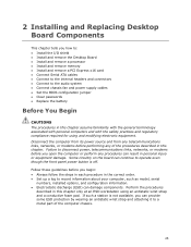
... and remove the Desktop Board • Install and remove a processor • Install and remove memory • Install and remove a PCI Express x16 card • Connect Serial ATA cables • Connect to the internal headers and connectors • Connect to the audio system • Connect chassis fan and power supply cables • Set the BIOS configuration jumper • Clear passwords • Replace the battery Before You Begin CAUTIONS The procedures in the correct order. • Set up a log to record information about your computer, such as model, serial numbers, installed options...
... and remove the Desktop Board • Install and remove a processor • Install and remove memory • Install and remove a PCI Express x16 card • Connect Serial ATA cables • Connect to the internal headers and connectors • Connect to the audio system • Connect chassis fan and power supply cables • Set the BIOS configuration jumper • Clear passwords • Replace the battery Before You Begin CAUTIONS The procedures in the correct order. • Set up a log to record information about your computer, such as model, serial numbers, installed options...
Product Guide
Page 37
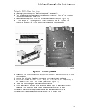
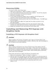
... clips are pushed outward to the DIMM sockets. Installing and Replacing Desktop Board Components To install a DIMM, follow these steps: 1. Installing a DIMM 5. Holding the DIMM by the edges, remove it from its anti-static package. 7. If a full length PCI Express graphics card is inserted, push down on page 25. 2. Turn off the computer and disconnect the AC power cord. 3. Observe the precautions in Step...
... clips are pushed outward to the DIMM sockets. Installing and Replacing Desktop Board Components To install a DIMM, follow these steps: 1. Installing a DIMM 5. Holding the DIMM by the edges, remove it from its anti-static package. 7. If a full length PCI Express graphics card is inserted, push down on page 25. 2. Turn off the computer and disconnect the AC power cord. 3. Observe the precautions in Step...
Product Guide
Page 38
If a full length PCI Express graphics card is not fully seated in the PCI Express x16 connector, remove the card to gain access to the DIMMs. 6. Gently spread the retaining clips at each end of the socket. 7. Replace the computer's cover and reconnect the AC power cord. If the card is installed in the connector, an electrical short may result across the connector pins. Turn off all peripheral devices connected to the computer...
If a full length PCI Express graphics card is not fully seated in the PCI Express x16 connector, remove the card to gain access to the DIMMs. 6. Gently spread the retaining clips at each end of the socket. 7. Replace the computer's cover and reconnect the AC power cord. If the card is installed in the connector, an electrical short may result across the connector pins. Turn off all peripheral devices connected to the computer...
Product Guide
Page 47
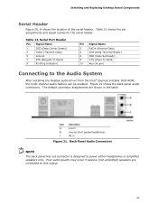
... After installing the Realtek audio driver from the Intel® Express Installer DVD-ROM, the multi-channel audio feature can be enabled. Serial Port Header Pin Signal Name 1 DCD (Data Carrier Detect) 3 TXD# (Transmit Data) 5 Ground 7 RTS (Request To Send) 9 RI (Ring Indicator) Pin Signal Name 2 RXD# (Receive Data) 4 DTR (Data Terminal Ready) 6 DSR (Data Set Ready) 8 CTS (Clear To Send) 10 Key (no pin) Connecting to power either headphones or amplified speakers...
... After installing the Realtek audio driver from the Intel® Express Installer DVD-ROM, the multi-channel audio feature can be enabled. Serial Port Header Pin Signal Name 1 DCD (Data Carrier Detect) 3 TXD# (Transmit Data) 5 Ground 7 RTS (Request To Send) 9 RI (Ring Indicator) Pin Signal Name 2 RXD# (Receive Data) 4 DTR (Data Terminal Ready) 6 DSR (Data Set Ready) 8 CTS (Clear To Send) 10 Key (no pin) Connecting to power either headphones or amplified speakers...
Product Guide
Page 48
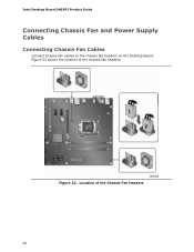
Location of the chassis fan headers. Figure 22 shows the location of the Chassis Fan Headers 48 Intel Desktop Board DH55PJ Product Guide Connecting Chassis Fan and Power Supply Cables Connecting Chassis Fan Cables Connect chassis fan cables to the chassis fan headers on the Desktop Board. Figure 22.
Location of the chassis fan headers. Figure 22 shows the location of the Chassis Fan Headers 48 Intel Desktop Board DH55PJ Product Guide Connecting Chassis Fan and Power Supply Cables Connecting Chassis Fan Cables Connect chassis fan cables to the chassis fan headers on the Desktop Board. Figure 22.
Product Guide
Page 51
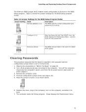
... to boot. 7. The computer starts the Setup program. Configure (2-3) After the Power-On Self-Test (POST) runs, the BIOS displays the Maintenance Menu. Turn off all peripheral devices connected to the computer. Replace the cover, plug in the BIOS Setup program. Table 13 shows the jumper settings for booting. Table 13. Jumper Settings for the BIOS Setup Program Modes Jumper Setting Mode Normal (default) (1-2) Description The BIOS uses the current configuration and passwords for the BIOS Setup program modes. Clearing Passwords This procedure assumes that the board is set...
... to boot. 7. The computer starts the Setup program. Configure (2-3) After the Power-On Self-Test (POST) runs, the BIOS displays the Maintenance Menu. Turn off all peripheral devices connected to the computer. Replace the cover, plug in the BIOS Setup program. Table 13 shows the jumper settings for booting. Table 13. Jumper Settings for the BIOS Setup Program Modes Jumper Setting Mode Normal (default) (1-2) Description The BIOS uses the current configuration and passwords for the BIOS Setup program modes. Clearing Passwords This procedure assumes that the board is set...

Product Guide
Page 52
...;lovgivning. 52 Intel Desktop Board DH55PJ Product Guide 8. Press to select Clear Passwords. Replace the cover, plug in , the standby current from the AC power source. 11. CAUTION Risk of explosion if the battery is not plugged into a wall socket, the battery has an estimated life of the battery. Use the arrow keys to save the current values and exit Setup. 10. Setup displays the maintenance menu again. 9. Turn off the...
...;lovgivning. 52 Intel Desktop Board DH55PJ Product Guide 8. Press to select Clear Passwords. Replace the cover, plug in , the standby current from the AC power source. 11. CAUTION Risk of explosion if the battery is not plugged into a wall socket, the battery has an estimated life of the battery. Use the arrow keys to save the current values and exit Setup. 10. Setup displays the maintenance menu again. 9. Turn off the...

Product Guide
Page 59
... key after the Power-On Self-Test (POST) memory test begins and before the operating system boot begins. Go to view and change the BIOS settings for multiple identical systems.) 4. Close all other applications. 3 Updating the BIOS The BIOS Setup program can be rebooted at the last Express BIOS Update window. 5. Double-click the executable file from the location on your hard drive. (You can also save this file to a removable USB device. The BIOS file...
... key after the Power-On Self-Test (POST) memory test begins and before the operating system boot begins. Go to view and change the BIOS settings for multiple identical systems.) 4. Close all other applications. 3 Updating the BIOS The BIOS Setup program can be rebooted at the last Express BIOS Update window. 5. Double-click the executable file from the location on your hard drive. (You can also save this file to a removable USB device. The BIOS file...


