
Product Specification
Page 5
... Product Specification (TPS) specifies the board layout, components, connectors, power and environmental requirements, and the BIOS for general audiences. v CAUTION Cautions are included to important information. What This Document Contains Chapter 1 2 3 4 5 Description A description of the hardware used on the Intel Desktop Board DH61WW A map of the resources of the Intel Desktop Board The features supported by the BIOS Setup program A description of the BIOS error messages, beep codes, and POST codes Regulatory...
... Product Specification (TPS) specifies the board layout, components, connectors, power and environmental requirements, and the BIOS for general audiences. v CAUTION Cautions are included to important information. What This Document Contains Chapter 1 2 3 4 5 Description A description of the hardware used on the Intel Desktop Board DH61WW A map of the resources of the Intel Desktop Board The features supported by the BIOS Setup program A description of the BIOS error messages, beep codes, and POST codes Regulatory...
Product Specification
Page 8
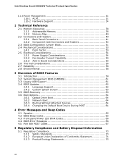
... Environmental 58 3 Overview of BIOS Features 3.1 Introduction 59 3.2 System Management BIOS (SMBIOS 61 3.3 Legacy USB Support 61 3.4 BIOS Updates 62 3.4.1 Language Support 62 3.4.2 Custom Splash Screen 63 3.5 BIOS Recovery 63 3.6 Boot Options 64 3.6.1 Optical Drive Boot 64 3.6.2 Network Boot 64 3.6.3 Booting Without Attached Devices 64 3.6.4 Changing the Default Boot Device During POST 64 4 Error Messages and Beep Codes 4.1 Speaker 65 4.2 BIOS Beep Codes 65 4.3 Front-panel Power LED Blink Codes 66 4.4 BIOS Error Messages 66 4.5 Port 80h POST Codes 67 5 Regulatory Compliance...
... Environmental 58 3 Overview of BIOS Features 3.1 Introduction 59 3.2 System Management BIOS (SMBIOS 61 3.3 Legacy USB Support 61 3.4 BIOS Updates 62 3.4.1 Language Support 62 3.4.2 Custom Splash Screen 63 3.5 BIOS Recovery 63 3.6 Boot Options 64 3.6.1 Optical Drive Boot 64 3.6.2 Network Boot 64 3.6.3 Booting Without Attached Devices 64 3.6.4 Changing the Default Boot Device During POST 64 4 Error Messages and Beep Codes 4.1 Speaker 65 4.2 BIOS Beep Codes 65 4.3 Front-panel Power LED Blink Codes 66 4.4 BIOS Error Messages 66 4.5 Port 80h POST Codes 67 5 Regulatory Compliance...
Product Specification
Page 9
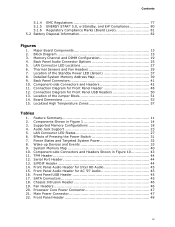
... 15. Supported Memory Configurations 18 4. Front Panel Audio Header for Intel HD Audio 45 15. Front Panel Header 48 ix Thermal Sensors and Fan Headers 29 7. Front Panel USB Header 45 17. Location of the Standby Power LED (Green 37 8. Back Panel Connectors 41 10. Localized High Temperature Zones 57 Tables 1. Wake-up Devices and Events 33 9. TPM Header 44 12. Main Power Connector 47 22. Block Diagram 15 3. Serial Port Header 44 13. Chassis Intrusion Header 46 19. System Memory Map 40 10. LAN Connector LED States...
... 15. Supported Memory Configurations 18 4. Front Panel Audio Header for Intel HD Audio 45 15. Front Panel Header 48 ix Thermal Sensors and Fan Headers 29 7. Front Panel USB Header 45 17. Location of the Standby Power LED (Green 37 8. Back Panel Connectors 41 10. Localized High Temperature Zones 57 Tables 1. Wake-up Devices and Events 33 9. TPM Header 44 12. Main Power Connector 47 22. Block Diagram 15 3. Serial Port Header 44 13. Chassis Intrusion Header 46 19. System Memory Map 40 10. LAN Connector LED States...
Product Specification
Page 10
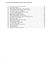
.... BIOS Setup Program Function Keys 60 32. Front-panel Power LED Blink Codes 66 36. Port 80h POST Codes 68 39. Regulatory Compliance Marks 81 x BIOS Error Messages 66 37. Safety Standards 73 41. Intel Desktop Board DH61WW Technical Product Specification 23. States for a One-Color Power LED 49 24. LPC Debug Header 50 25. BIOS Setup Program Menu Bar 60 31. BIOS Beep Codes 65 35. Recommended Power Supply Current Values 54 27. Boot Device Menu Options 64 34. BIOS Setup Configuration Jumper Settings 52...
.... BIOS Setup Program Function Keys 60 32. Front-panel Power LED Blink Codes 66 36. Port 80h POST Codes 68 39. Regulatory Compliance Marks 81 x BIOS Error Messages 66 37. Safety Standards 73 41. Intel Desktop Board DH61WW Technical Product Specification 23. States for a One-Color Power LED 49 24. LPC Debug Header 50 25. BIOS Setup Program Menu Bar 60 31. BIOS Beep Codes 65 35. Recommended Power Supply Current Values 54 27. Boot Device Menu Options 64 34. BIOS Setup Configuration Jumper Settings 52...

Product Specification
Page 12
...Flash device • Support for Advanced Configuration and Power Interface (ACPI), Plug and Play, and SMBIOS • Support for PCI* Local Bus Specification Revision 2.2 • Support for PCI Express* • Suspend to RAM support • Wake on Conventional PCI, PCI Express, LAN, front panel, serial, PS/2, and USB ports LAN Support Expansion Capabilities Hardware Monitor Subsystem Gigabit (10/100/1000 Mbits/s) LAN subsystem using the Intel® 82579V Gigabit Ethernet Controller • One PCI Express 2.0 x16 add-in card connector • One PCI Express 2.0 x1 add-in card connector...
...Flash device • Support for Advanced Configuration and Power Interface (ACPI), Plug and Play, and SMBIOS • Support for PCI* Local Bus Specification Revision 2.2 • Support for PCI Express* • Suspend to RAM support • Wake on Conventional PCI, PCI Express, LAN, front panel, serial, PS/2, and USB ports LAN Support Expansion Capabilities Hardware Monitor Subsystem Gigabit (10/100/1000 Mbits/s) LAN subsystem using the Intel® 82579V Gigabit Ethernet Controller • One PCI Express 2.0 x16 add-in card connector • One PCI Express 2.0 x1 add-in card connector...

Product Specification
Page 16
...com Supported processors Chipset information BIOS and driver updates Tested memory Integration information http://processormatch.intel.com http://www.intel.com/products/desktop/chipsets/index.htm http://downloadcenter.intel.com http://www.intel.com/support/motherboards/desktop/sb/CS025414.htm http://www.intel.com/support/go/buildit 1.4 Processor The board is designed to support the Intel Core i7, Intel Core i5, Intel Core i3, and Intel Pentium processors in the future. Supported processors Refer to the processor. Intel Desktop Board DH61WW Technical Product Specification 1.2 Legacy...
...com Supported processors Chipset information BIOS and driver updates Tested memory Integration information http://processormatch.intel.com http://www.intel.com/products/desktop/chipsets/index.htm http://downloadcenter.intel.com http://www.intel.com/support/motherboards/desktop/sb/CS025414.htm http://www.intel.com/support/go/buildit 1.4 Processor The board is designed to support the Intel Core i7, Intel Core i5, Intel Core i3, and Intel Pentium processors in the future. Supported processors Refer to the processor. Intel Desktop Board DH61WW Technical Product Specification 1.2 Legacy...

Product Specification
Page 17
... memory is a centralized controller for optimum performance. The PCH is installed, the BIOS will attempt to accurately configure memory settings for the board's I/O paths. For information about The Intel H61 Express chipset Resources used by the chipset Refer to http://www.intel.com/products/desktop/chipsets/index.htm Chapter 2 1.6 System Memory The board has two DIMM sockets and supports the following memory features: • Two independent memory channels with interleaved mode support • Supports 1.2 V - 1.8 V DIMM memory voltage • Support...
... memory is a centralized controller for optimum performance. The PCH is installed, the BIOS will attempt to accurately configure memory settings for the board's I/O paths. For information about The Intel H61 Express chipset Resources used by the chipset Refer to http://www.intel.com/products/desktop/chipsets/index.htm Chapter 2 1.6 System Memory The board has two DIMM sockets and supports the following memory features: • Two independent memory channels with interleaved mode support • Supports 1.2 V - 1.8 V DIMM memory voltage • Support...

Product Specification
Page 18
... be used when only a single DIMM is equivalent to the other . This mode is installed or the memory capacities are equal. Tested Memory Refer to the other but the installed memory capacity for real world applications. Technology and device width can vary from one channel to : http://support.intel.com/support/motherboards/desktop/sb/CS025414.htm 1.6.1 Memory Configurations The Intel Core i7, Intel Core i5, Intel Core i3, and Intel Pentium processors support the following types of...
... be used when only a single DIMM is equivalent to the other . This mode is installed or the memory capacities are equal. Tested Memory Refer to the other but the installed memory capacity for real world applications. Technology and device width can vary from one channel to : http://support.intel.com/support/motherboards/desktop/sb/CS025414.htm 1.6.1 Memory Configurations The Intel Core i7, Intel Core i5, Intel Core i3, and Intel Pentium processors support the following types of...

Product Specification
Page 26
... Specification 1.12 LAN Subsystem The LAN subsystem consists of the following: • Intel 82579V Gigabit Ethernet Controller (10/100/1000 Mbits/s) • Intel H61 Express Chipset • RJ-45 LAN connector with integrated status LEDs Additional features of the LAN subsystem include: • CSMA/CD protocol engine • LAN connect interface between the PCH and the LAN controller • PCI Conventional bus power management ⎯ ACPI technology support ⎯ LAN wake capabilities • LAN subsystem software...
... Specification 1.12 LAN Subsystem The LAN subsystem consists of the following: • Intel 82579V Gigabit Ethernet Controller (10/100/1000 Mbits/s) • Intel H61 Express Chipset • RJ-45 LAN connector with integrated status LEDs Additional features of the LAN subsystem include: • CSMA/CD protocol engine • LAN connect interface between the PCH and the LAN controller • PCI Conventional bus power management ⎯ ACPI technology support ⎯ LAN wake capabilities • LAN subsystem software...

Product Specification
Page 31
... Fail safe power-off the computer • Support for multiple wake-up events (see Table 8 on page 33) • Support for achieving less than four seconds Power-on (ACPI G0 - The use of individual devices, add-in boards (some add-in boards may require an ACPI-aware driver), video displays, and hard disk drives • Methods for a front panel power and sleep mode switch Table 6 lists the system states based on how long the power switch is...
... Fail safe power-off the computer • Support for multiple wake-up events (see Table 8 on page 33) • Support for achieving less than four seconds Power-on (ACPI G0 - The use of individual devices, add-in boards (some add-in boards may require an ACPI-aware driver), video displays, and hard disk drives • Methods for a front panel power and sleep mode switch Table 6 lists the system states based on how long the power switch is...
Product Specification
Page 50
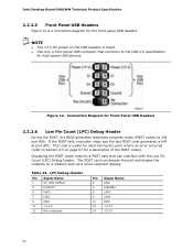
... for high-speed USB devices. The POST card can interface with the Low Pin Count (LPC) Debug header. Displaying the POST codes requires a POST card that conforms to the USB 2.0 specification for the front panel USB headers. Connection Diagram for Front Panel USB Headers 2.2.2.6 Low Pin Count (LPC) Debug Header During the POST, the BIOS generates diagnostic progress codes (POST codes) to Section 4.5 on the USB headers is useful for a description of the POST codes). Intel Desktop Board DH61WW Technical Product Specification 2.2.2.5 Front Panel USB Headers Figure 12 is left at port...
... for high-speed USB devices. The POST card can interface with the Low Pin Count (LPC) Debug header. Displaying the POST codes requires a POST card that conforms to the USB 2.0 specification for the front panel USB headers. Connection Diagram for Front Panel USB Headers 2.2.2.6 Low Pin Count (LPC) Debug Header During the POST, the BIOS generates diagnostic progress codes (POST codes) to Section 4.5 on the USB headers is useful for a description of the POST codes). Intel Desktop Board DH61WW Technical Product Specification 2.2.2.5 Front Panel USB Headers Figure 12 is left at port...
Product Specification
Page 59
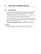
The SPI Flash contains the BIOS Setup program, POST, LAN EEPROM information, Plug and Play support, and other firmware. The BIOS displays a message during POST identifying the type of utilities. Maintenance Main Configuration Performance Security Power Boot Exit NOTE The maintenance menu is displayed only when the board is in configure mode. 59 The BIOS Setup program is shown below. Section 2.3 on page 51 shows how to view and change the BIOS settings for the computer. The initial...
The SPI Flash contains the BIOS Setup program, POST, LAN EEPROM information, Plug and Play support, and other firmware. The BIOS displays a message during POST identifying the type of utilities. Maintenance Main Configuration Performance Security Power Boot Exit NOTE The maintenance menu is displayed only when the board is in configure mode. 59 The BIOS Setup program is shown below. Section 2.3 on page 51 shows how to view and change the BIOS settings for the computer. The initial...
Product Specification
Page 60
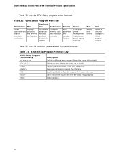
... Load the default configuration values for menu screens. Intel Desktop Board DH61WW Technical Product Specification Table 30 lists the BIOS Setup program menu features. tion Performance Clears passwords and displays processor information Displays processor and memory configuration Configures advanced features available through the chipset Configures Memory, Bus and Processor overrides Security Sets passwords and security features Power Configures power management features and power supply controls Boot Selects boot options Exit Saves or discards changes to Setup program options...
... Load the default configuration values for menu screens. Intel Desktop Board DH61WW Technical Product Specification Table 30 lists the BIOS Setup program menu features. tion Performance Clears passwords and displays processor information Displays processor and memory configuration Configures advanced features available through the chipset Configures Memory, Bus and Processor overrides Security Sets passwords and security features Power Configures power management features and power supply controls Boot Selects boot options Exit Saves or discards changes to Setup program options...

Product Specification
Page 61
... header under the Main BIOS page. 3.3 Legacy USB Support Legacy USB support enables USB devices to be used . 61 By default, Legacy USB support is set to install an operating system that supports USB. POST begins. 3. Legacy USB support is enabled by the operating system, and Legacy USB support from the BIOS is no longer used to configure the operating system. (Keyboards and mice are recognized by the BIOS allowing you apply power to enter and configure the BIOS Setup program and the maintenance menu. 4. After the operating system loads the USB drivers...
... header under the Main BIOS page. 3.3 Legacy USB Support Legacy USB support enables USB devices to be used . 61 By default, Legacy USB support is set to install an operating system that supports USB. POST begins. 3. Legacy USB support is enabled by the operating system, and Legacy USB support from the BIOS is no longer used to configure the operating system. (Keyboards and mice are recognized by the BIOS allowing you apply power to enter and configure the BIOS Setup program and the maintenance menu. 4. After the operating system loads the USB drivers...
Product Specification
Page 63
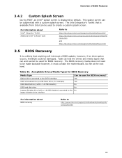
... a BIOS update; For information about BIOS recovery Refer to the SATA interface Yes USB removable drive (a USB Flash Drive, for example) Yes USB diskette drive (with a 1.44 MB diskette) No USB hard disk drive No Legacy diskette drive (with a custom splash screen. Optical drive connected to http://www.intel.com/support/motherboards/desktop/sb/ cs-023360.htm 63 Table 32. The Intel Integrator's Toolkit that can and cannot be used for BIOS recovery? Acceptable Drives/Media Types for BIOS Recovery Media Type Can be used for BIOS recovery...
... a BIOS update; For information about BIOS recovery Refer to the SATA interface Yes USB removable drive (a USB Flash Drive, for example) Yes USB diskette drive (with a 1.44 MB diskette) No USB hard disk drive No Legacy diskette drive (with a custom splash screen. Optical drive connected to http://www.intel.com/support/motherboards/desktop/sb/ cs-023360.htm 63 Table 32. The Intel Integrator's Toolkit that can and cannot be used for BIOS recovery? Acceptable Drives/Media Types for BIOS Recovery Media Type Can be used for BIOS recovery...
Product Specification
Page 64
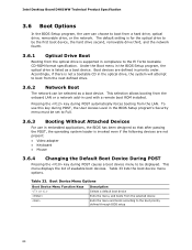
...Network Boot The network can choose to boot from the selected device Exits the menu and boots according to the boot priority defined through BIOS setup 64 This menu displays the list of available boot devices. Boot Device Menu Options Boot Device Menu Function Keys or Description Selects a default boot device Exits the menu, and boots from a hard drive, optical drive, removable drive, or the network. Intel Desktop Board DH61WW Technical Product Specification 3.6 Boot Options In the BIOS Setup program, the user can be set to Full. 3.6.3 Booting Without Attached Devices For use...
...Network Boot The network can choose to boot from the selected device Exits the menu and boots according to the boot priority defined through BIOS setup 64 This menu displays the list of available boot devices. Boot Device Menu Options Boot Device Menu Function Keys or Description Selects a default boot device Exits the menu, and boots from a hard drive, optical drive, removable drive, or the network. Intel Desktop Board DH61WW Technical Product Specification 3.6 Boot Options In the BIOS Setup program, the user can be set to Full. 3.6.3 Booting Without Attached Devices For use...
Product Specification
Page 65
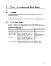
BIOS Beep Codes Type Pattern F2 Setup/F10 Boot Menu One 0.5 second beep when BIOS is powered off ), entire pattern repeats (beeps and pause) once and the BIOS will continue to boot. Frequency/Comments 932 Hz 932 Hz For processors requiring an add-in graphics card installed) On-off (1.0 second each ) three times, then 2.5-second pause (off), entire pattern repeats (beeps and pause) until the system is ready to beep an...
BIOS Beep Codes Type Pattern F2 Setup/F10 Boot Menu One 0.5 second beep when BIOS is powered off ), entire pattern repeats (beeps and pause) once and the BIOS will continue to boot. Frequency/Comments 932 Hz 932 Hz For processors requiring an add-in graphics card installed) On-off (1.0 second each ) three times, then 2.5-second pause (off), entire pattern repeats (beeps and pause) until the system is ready to beep an...
Product Specification
Page 66
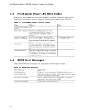
..., .25 seconds off, .25 seconds on for 0.5 seconds, then off . Front-panel Power LED Blink Codes Type Pattern F2 Setup/F10 Boot Menu None Prompt BIOS update in graphics card installed) Memory error On-off (1.0 second each) two times, then 2.5-second pause (off . Intel Desktop Board DH61WW Technical Product Specification 4.3 Front-panel Power LED Blink Codes Whenever a recoverable error occurs during POST, the BIOS causes the board's front panel power LED to blink an error message describing the problem (see Table 35).
..., .25 seconds off, .25 seconds on for 0.5 seconds, then off . Front-panel Power LED Blink Codes Type Pattern F2 Setup/F10 Boot Menu None Prompt BIOS update in graphics card installed) Memory error On-off (1.0 second each) two times, then 2.5-second pause (off . Intel Desktop Board DH61WW Technical Product Specification 4.3 Front-panel Power LED Blink Codes Whenever a recoverable error occurs during POST, the BIOS causes the board's front panel power LED to blink an error message describing the problem (see Table 35).

Product Specification
Page 67
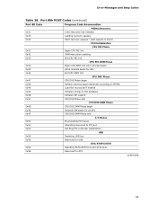
... MRC execution MRC memory detection PEI phase post MRC execution Recovery Platform DXE driver CPU Initialization (PEI, DXE, SMM) I /O port 80h. For future use Input devices: Keyboard/Mouse. This code is useful for determining the point where an error occurred. S2, 0x30 - Start with the Low Pin Count (LPC) Debug header. BDS Output devices: All output consoles. Not that can decode the port and display the contents on...
... MRC execution MRC memory detection PEI phase post MRC execution Recovery Platform DXE driver CPU Initialization (PEI, DXE, SMM) I /O port 80h. For future use Input devices: Keyboard/Mouse. This code is useful for determining the point where an error occurred. S2, 0x30 - Start with the Low Pin Count (LPC) Debug header. BDS Output devices: All output consoles. Not that can decode the port and display the contents on...
Product Specification
Page 69
... SMM Phase 0x4D CPU DXE SMM Phase begin 0x4E Relocate SM bases for all APs 0x4F CPU DXE SMM Phase end I/O Buses 0x50 Enumerating PCI buses 0x51 Allocating resources to PCI bus 0x52 Hot Plug PCI controller initialization USB 0x58 Resetting USB bus 0x59 Reserved for USB ATA/ATAPI/SATA 0x5A Resetting PATA/SATA bus and all devices 0x5B Reserved for ATA continued 69 Error Messages and Beep Codes Table 38.
... SMM Phase 0x4D CPU DXE SMM Phase begin 0x4E Relocate SM bases for all APs 0x4F CPU DXE SMM Phase end I/O Buses 0x50 Enumerating PCI buses 0x51 Allocating resources to PCI bus 0x52 Hot Plug PCI controller initialization USB 0x58 Resetting USB bus 0x59 Reserved for USB ATA/ATAPI/SATA 0x5A Resetting PATA/SATA bus and all devices 0x5B Reserved for ATA continued 69 Error Messages and Beep Codes Table 38.


