
Product Specification
Page 2
... from 8 GB to 16 GB Date February 2011 May 2011 March 2012 Disclaimer This product specification applies to only the standard Intel® Desktop Board DH61WW with BIOS identifier BEH6110H.86A. All rights reserved. All Intel® desktop boards are available on the absence or characteristics of any license, express or implied, by...
... from 8 GB to 16 GB Date February 2011 May 2011 March 2012 Disclaimer This product specification applies to only the standard Intel® Desktop Board DH61WW with BIOS identifier BEH6110H.86A. All rights reserved. All Intel® desktop boards are available on the absence or characteristics of any license, express or implied, by...

Product Specification
Page 3
...Map ― Table 9. Feature Summary has been deleted ― Section 1.9.1.1 Serial ATA RAID has been deleted ― Section 1.9.1.2 Intel® Rapid Recover Technology has been deleted ― The Caution in Section 3.1 Introduction has been deleted • The maximum memory ...Compliance Marks (Board Level). Updated maximum memory supported from 16 GB to the Intel® Desktop Board DH61WW. Board Identification Information Basic Desktop Board DH61WW Identification Information AA Revision BIOS Revision Notes G23116-202 BEH6110H.86A.0016 1,2 G23116-203 BEH6110H.86A.0016 1,2...
...Map ― Table 9. Feature Summary has been deleted ― Section 1.9.1.1 Serial ATA RAID has been deleted ― Section 1.9.1.2 Intel® Rapid Recover Technology has been deleted ― The Caution in Section 3.1 Introduction has been deleted • The maximum memory ...Compliance Marks (Board Level). Updated maximum memory supported from 16 GB to the Intel® Desktop Board DH61WW. Board Identification Information Basic Desktop Board DH61WW Identification Information AA Revision BIOS Revision Notes G23116-202 BEH6110H.86A.0016 1,2 G23116-203 BEH6110H.86A.0016 1,2...

Product Specification
Page 5
... data. It is intended to provide detailed, technical information about the conventions used on the Intel Desktop Board DH61WW A map of the resources of the Intel Desktop Board The features supported by the BIOS Setup program A description of the BIOS error messages, beep codes, and POST codes Regulatory compliance and battery disposal information Typographical...
... data. It is intended to provide detailed, technical information about the conventions used on the Intel Desktop Board DH61WW A map of the resources of the Intel Desktop Board The features supported by the BIOS Setup program A description of the BIOS error messages, beep codes, and POST codes Regulatory compliance and battery disposal information Typographical...
Product Specification
Page 8
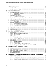
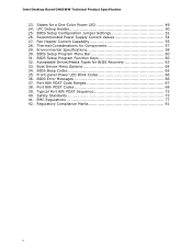
Intel Desktop Board DH61WW Technical Product Specification 1.16 Power Management 31 1.16.1 ACPI 31 1.16.2 Hardware Support 34 2 Technical Reference 2.1 Memory Resources 38 2.1.1 Addressable Memory 38 2.1.2 Memory Map 40 2.2 Connectors and Headers 40 2.2.1 Back Panel Connectors 41 2.2.2 Component-side Connectors and Headers 42 2.3 BIOS...Default Boot Device During POST 64 4 Error Messages and Beep Codes 4.1 Speaker 65 4.2 BIOS Beep Codes 65 4.3 Front-panel Power LED Blink Codes 66 4.4 BIOS Error Messages 66 4.5 Port 80h POST Codes 67 5 Regulatory Compliance and Battery Disposal ...
Intel Desktop Board DH61WW Technical Product Specification 1.16 Power Management 31 1.16.1 ACPI 31 1.16.2 Hardware Support 34 2 Technical Reference 2.1 Memory Resources 38 2.1.1 Addressable Memory 38 2.1.2 Memory Map 40 2.2 Connectors and Headers 40 2.2.1 Back Panel Connectors 41 2.2.2 Component-side Connectors and Headers 42 2.3 BIOS...Default Boot Device During POST 64 4 Error Messages and Beep Codes 4.1 Speaker 65 4.2 BIOS Beep Codes 65 4.3 Front-panel Power LED Blink Codes 66 4.4 BIOS Error Messages 66 4.5 Port 80h POST Codes 67 5 Regulatory Compliance and Battery Disposal ...
Product Specification
Page 10
... 32. Port 80h POST Code Ranges 67 38. Typical Port 80h POST Sequence 72 40. Environmental Specifications 58 30. BIOS Error Messages 66 37. Intel Desktop Board DH61WW Technical Product Specification 23. BIOS Setup Program Menu Bar 60 31. EMC Regulations 77 42. Fan Header Current Capability 55 28. Regulatory Compliance Marks 81...
... 32. Port 80h POST Code Ranges 67 38. Typical Port 80h POST Sequence 72 40. Environmental Specifications 58 30. BIOS Error Messages 66 37. Intel Desktop Board DH61WW Technical Product Specification 23. BIOS Setup Program Menu Bar 60 31. EMC Regulations 77 42. Fan Header Current Capability 55 28. Regulatory Compliance Marks 81...

Product Specification
Page 12
... PS/2* keyboard/mouse port on back panel • Nuvoton* W83677HG-i Super I/O controller for hardware management and serial port, parallel port, and PS/2 support • Intel® BIOS resident in the SPI Flash device • Support for Advanced Configuration and Power Interface (ACPI), Plug and Play, and SMBIOS • Support for PCI* Local...
... PS/2* keyboard/mouse port on back panel • Nuvoton* W83677HG-i Super I/O controller for hardware management and serial port, parallel port, and PS/2 support • Intel® BIOS resident in the SPI Flash device • Support for Advanced Configuration and Power Interface (ACPI), Plug and Play, and SMBIOS • Support for PCI* Local...

Product Specification
Page 16
.../p/en_US/support?iid=hdr+support http://ark.intel.com Supported processors Chipset information BIOS and driver updates Tested memory Integration information http://processormatch.intel.com http://www.intel.com/products/desktop/chipsets/index.htm http://downloadcenter.intel.com http://www.intel.com/support/motherboards/desktop/sb/CS025414.htm http://www.intel.com/support/go/buildit 1.4 Processor The...
.../p/en_US/support?iid=hdr+support http://ark.intel.com Supported processors Chipset information BIOS and driver updates Tested memory Integration information http://processormatch.intel.com http://www.intel.com/products/desktop/chipsets/index.htm http://downloadcenter.intel.com http://www.intel.com/support/motherboards/desktop/sb/CS025414.htm http://www.intel.com/support/go/buildit 1.4 Processor The...

Product Specification
Page 17
...may be populated with DIMMs that support the Serial Presence Detect (SPD) data structure. This allows the BIOS to read the SPD data and program the chipset to http://www.intel.com/products/desktop/chipsets/index.htm Chapter 2 1.6 System Memory The board has two DIMM sockets and ...supports the following memory features: • Two independent memory channels with 4 Gb memory technology). For information about The Intel H61 Express chipset Resources used by the chipset Refer to accurately configure memory settings for non-ECC, unbuffered, single-sided or double-sided ...
...may be populated with DIMMs that support the Serial Presence Detect (SPD) data structure. This allows the BIOS to read the SPD data and program the chipset to http://www.intel.com/products/desktop/chipsets/index.htm Chapter 2 1.6 System Memory The board has two DIMM sockets and ...supports the following memory features: • Two independent memory channels with 4 Gb memory technology). For information about The Intel H61 Express chipset Resources used by the chipset Refer to accurately configure memory settings for non-ECC, unbuffered, single-sided or double-sided ...
Product Specification
Page 22
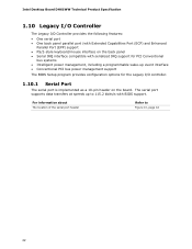
... Capabilities Port (ECP) and Enhanced Parallel Port (EPP) support • PS/2-style keyboard/mouse interface on the back panel • Serial IRQ interface compatible with BIOS support. Intel Desktop Board DH61WW Technical Product Specification 1.10 Legacy I/O Controller The Legacy I /O controller. 1.10.1 Serial Port The serial port is implemented as a 10-pin header...
... Capabilities Port (ECP) and Enhanced Parallel Port (EPP) support • PS/2-style keyboard/mouse interface on the back panel • Serial IRQ interface compatible with BIOS support. Intel Desktop Board DH61WW Technical Product Specification 1.10 Legacy I/O Controller The Legacy I /O controller. 1.10.1 Serial Port The serial port is implemented as a 10-pin header...
Product Specification
Page 28
Figure 1 on page 13 shows the location of three years. When the voltage drops below a certain level, the BIOS Setup program settings stored in , the standby current from the power supply extends the life of the battery. NOTE If the battery and AC power ... a wall socket, the battery has an estimated life of the battery. 28 Replace the battery with power applied through the power supply 5V STBY rail. Intel Desktop Board DH61WW Technical Product Specification 1.13 Real-Time Clock Subsystem A coin-cell battery (CR2032) powers the real-time clock and CMOS memory.
Figure 1 on page 13 shows the location of three years. When the voltage drops below a certain level, the BIOS Setup program settings stored in , the standby current from the power supply extends the life of the battery. NOTE If the battery and AC power ... a wall socket, the battery has an estimated life of the battery. 28 Replace the battery with power applied through the power supply 5V STBY rail. Intel Desktop Board DH61WW Technical Product Specification 1.13 Real-Time Clock Subsystem A coin-cell battery (CR2032) powers the real-time clock and CMOS memory.
Product Specification
Page 30
... to the chassis intrusion header. When the chassis cover is removed, the mechanical switch is in the closed position. Intel Desktop Board DH61WW Technical Product Specification 1.15 Platform Management and Security Intel DH61WW Desktop Board integrates several hardware management features, including the following: • Fan monitoring and control • Thermal...designed to manage the system and lower the total cost of ownership (TCO) of the chassis intrusion header Refer to be observed through the BIOS setup user interface, Intel® Desktop Utilities or third-party software.
... to the chassis intrusion header. When the chassis cover is removed, the mechanical switch is in the closed position. Intel Desktop Board DH61WW Technical Product Specification 1.15 Platform Management and Security Intel DH61WW Desktop Board integrates several hardware management features, including the following: • Fan monitoring and control • Thermal...designed to manage the system and lower the total cost of ownership (TCO) of the chassis intrusion header Refer to be observed through the BIOS setup user interface, Intel® Desktop Utilities or third-party software.
Product Specification
Page 34
Intel Desktop Board DH61WW Technical Product Specification 1.16.2 Hardware Support CAUTION Ensure that provides full ACPI support. 1.16.2.1 Power Connector ATX12V-compliant power supplies can turn ... wake capabilities and Instantly Available PC technology require power from an AC power failure, the computer returns to the power state it was in the BIOS Setup program's Boot menu. The computer's response can damage the power supply. When resuming from the +5 V standby line. When an ACPI-enabled system receives the...
Intel Desktop Board DH61WW Technical Product Specification 1.16.2 Hardware Support CAUTION Ensure that provides full ACPI support. 1.16.2.1 Power Connector ATX12V-compliant power supplies can turn ... wake capabilities and Instantly Available PC technology require power from an AC power failure, the computer returns to the power state it was in the BIOS Setup program's Boot menu. The computer's response can damage the power supply. When resuming from the +5 V standby line. When an ACPI-enabled system receives the...

Product Specification
Page 36
...PME# Signal Wake-up Support When the PME# signal on the keyboard. 36 Instantly Available PC technology enables the board to wake the computer. Intel Desktop Board DH61WW Technical Product Specification 1.16.2.4 Instantly Available PC Technology CAUTION For Instantly Available PC technology, the +5 V standby line for the ...power supply must be off (the power supply is off and the front panel power LED will behave as configured by the BIOS "S3 State Indicator" option). Failure to provide adequate standby current when implementing Instantly Available PC technology can be used to enter the ...
...PME# Signal Wake-up Support When the PME# signal on the keyboard. 36 Instantly Available PC technology enables the board to wake the computer. Intel Desktop Board DH61WW Technical Product Specification 1.16.2.4 Instantly Available PC Technology CAUTION For Instantly Available PC technology, the +5 V standby line for the ...power supply must be off (the power supply is off and the front panel power LED will behave as configured by the BIOS "S3 State Indicator" option). Failure to provide adequate standby current when implementing Instantly Available PC technology can be used to enter the ...
Product Specification
Page 38
... installed system memory can be used when there is allocated for Conventional PCI and PCI Express add-in cards, PCI Express configuration space, BIOS (SPI Flash device), and chipset overhead resides above the 4 GB boundary. Typically the address space that is no overlap of the system... memory map. These functions include the following: • BIOS/SPI Flash device (32 Mbit) • Local APIC (19 MB) • Direct Media Interface (40 MB) • PCI Express configuration space (256 ...
... installed system memory can be used when there is allocated for Conventional PCI and PCI Express add-in cards, PCI Express configuration space, BIOS (SPI Flash device), and chipset overhead resides above the 4 GB boundary. Typically the address space that is no overlap of the system... memory map. These functions include the following: • BIOS/SPI Flash device (32 Mbit) • Local APIC (19 MB) • Direct Media Interface (40 MB) • PCI Express configuration space (256 ...

Product Specification
Page 40
...K - 639 K 0 K - 512 K A0000 - Video memory and BIOS Extended BIOS data (movable by the external devices could cause damage to the board. Do not use these groups: • Back panel I/O connectors • Component-side I/O connectors and headers (see page 42) 40 Intel Desktop Board DH61WW Technical Product Specification 2.1.2 Memory Map Table...00000 - 7FFFF Size 16382 MB 64 KB 64 KB 96 KB 160 KB 1 KB 127 KB 512 KB Description Extended memory Runtime BIOS Reserved Potential available high DOS memory (open to the PCI bus). The connectors can be divided into these connectors or headers to ...
...K - 639 K 0 K - 512 K A0000 - Video memory and BIOS Extended BIOS data (movable by the external devices could cause damage to the board. Do not use these groups: • Back panel I/O connectors • Component-side I/O connectors and headers (see page 42) 40 Intel Desktop Board DH61WW Technical Product Specification 2.1.2 Memory Map Table...00000 - 7FFFF Size 16382 MB 64 KB 64 KB 96 KB 160 KB 1 KB 127 KB 512 KB Description Extended memory Runtime BIOS Reserved Potential available high DOS memory (open to the PCI bus). The connectors can be divided into these connectors or headers to ...
Product Specification
Page 49
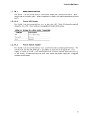
or two-color LED. More options are available through BIOS setup. The switch must pull the SW_ON# pin to ground for at least 50 ms to signal the power supply to switch on or off. (...
or two-color LED. More options are available through BIOS setup. The switch must pull the SW_ON# pin to ground for at least 50 ms to signal the power supply to switch on or off. (...
Product Specification
Page 50
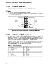
...2 GND 4 LFRAME# 6 LAD1 8 LAD3 10 GND 12 +3.3 V 14 +3.3 V 50 The POST card can interface with the Low Pin Count (LPC) Debug header. Intel Desktop Board DH61WW Technical Product Specification 2.2.2.5 Front Panel USB Headers Figure 12 is useful for determining the point where an error occurred (refer to Section... that conforms to I/O port 80h. Connection Diagram for Front Panel USB Headers 2.2.2.6 Low Pin Count (LPC) Debug Header During the POST, the BIOS generates diagnostic progress codes (POST codes) to the USB 2.0 specification for high-speed USB devices. Figure 12.
...2 GND 4 LFRAME# 6 LAD1 8 LAD3 10 GND 12 +3.3 V 14 +3.3 V 50 The POST card can interface with the Low Pin Count (LPC) Debug header. Intel Desktop Board DH61WW Technical Product Specification 2.2.2.5 Front Panel USB Headers Figure 12 is useful for determining the point where an error occurred (refer to Section... that conforms to I/O port 80h. Connection Diagram for Front Panel USB Headers 2.2.2.6 Low Pin Count (LPC) Debug Header During the POST, the BIOS generates diagnostic progress codes (POST codes) to the USB 2.0 specification for high-speed USB devices. Figure 12.
Product Specification
Page 51
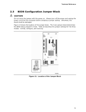
The 3-pin jumper block determines the BIOS Setup program's mode. Location of the jumper block. Otherwise, the board could be damaged. Figure 13. Always turn off the power and unplug the power cord from the computer before changing a jumper setting. Table 25 describes the jumper settings for the three modes: normal, configure, and recovery. Technical Reference 2.3 BIOS Configuration Jumper Block CAUTION Do not move the jumper with the power on. Figure 13 shows the location of the Jumper Block 51
The 3-pin jumper block determines the BIOS Setup program's mode. Location of the jumper block. Otherwise, the board could be damaged. Figure 13. Always turn off the power and unplug the power cord from the computer before changing a jumper setting. Table 25 describes the jumper settings for the three modes: normal, configure, and recovery. Technical Reference 2.3 BIOS Configuration Jumper Block CAUTION Do not move the jumper with the power on. Figure 13 shows the location of the Jumper Block 51
Product Specification
Page 52
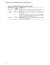
... the POST runs, Setup runs automatically. BIOS Setup Configuration Jumper Settings Function/Mode Normal Configure Jumper Setting 1-2 2-3 Configuration The BIOS uses current configuration information and passwords for booting. Press F9 (restore defaults) while in Configure mode to restore the BIOS/CMOS settings to their default values. Intel Desktop Board DH61WW Technical Product Specification Table...
... the POST runs, Setup runs automatically. BIOS Setup Configuration Jumper Settings Function/Mode Normal Configure Jumper Setting 1-2 2-3 Configuration The BIOS uses current configuration information and passwords for booting. Press F9 (restore defaults) while in Configure mode to restore the BIOS/CMOS settings to their default values. Intel Desktop Board DH61WW Technical Product Specification Table...
Product Specification
Page 59
... mode. Section 2.3 on page 51 shows how to view and change the BIOS settings for the computer. The initial production BIOSs are identified as BEH6110H.86A. 3 Overview of BIOS Features 3.1 Introduction The board uses an Intel BIOS that is stored in a 32 Mbit (8.192 KB) Serial Peripheral Interface Flash... Memory (SPI Flash) device which can be updated using a set of BIOS and a revision code. The menu bar is ...
... mode. Section 2.3 on page 51 shows how to view and change the BIOS settings for the computer. The initial production BIOSs are identified as BEH6110H.86A. 3 Overview of BIOS Features 3.1 Introduction The board uses an Intel BIOS that is stored in a 32 Mbit (8.192 KB) Serial Peripheral Interface Flash... Memory (SPI Flash) device which can be updated using a set of BIOS and a revision code. The menu bar is ...


