
Product Guide
Page 5
Contents 1 Desktop Board Features Supported Operating Systems 11 Desktop Board Components 12 Processor ...14 Main Memory...15 Intel® P55 Express Chipset 16 Audio Subsystem 16 LAN Subsystem 16 Bluetooth* Technology Support 17 USB 2.0 Support 17 Serial ATA Support 18 ... Configuration 20 PCI* and PCI Express* Auto Configuration 20 Security Passwords 20 Hardware Management 21 Hardware Monitoring and Fan Speed Control 21 Intel® Precision Cooling Technology 21 Chassis Intrusion 21 Power Management 22 Software Support 22 ACPI 22 Hardware Support 22 Power Connectors 22 Fan...
Contents 1 Desktop Board Features Supported Operating Systems 11 Desktop Board Components 12 Processor ...14 Main Memory...15 Intel® P55 Express Chipset 16 Audio Subsystem 16 LAN Subsystem 16 Bluetooth* Technology Support 17 USB 2.0 Support 17 Serial ATA Support 18 ... Configuration 20 PCI* and PCI Express* Auto Configuration 20 Security Passwords 20 Hardware Management 21 Hardware Monitoring and Fan Speed Control 21 Intel® Precision Cooling Technology 21 Chassis Intrusion 21 Power Management 22 Software Support 22 ACPI 22 Hardware Support 22 Power Connectors 22 Fan...
Product Guide
Page 6
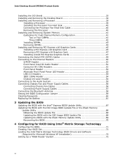
... Passwords 60 Replacing the Battery 61 3 Updating the BIOS Updating the BIOS with the Intel® Express BIOS Update Utility 67 Updating the BIOS with the ISO Image BIOS Update File or the Iflash Memory Update Utility 68 Obtaining the BIOS Update File 68 Updating the BIOS with the ISO ...Image BIOS Update File 68 Updating the BIOS with the Iflash Memory Update Utility 69 Recovering the BIOS 70 4 Configuring for RAID Using Intel® Matrix Storage Technology Configuring the BIOS 71 Creating Your RAID Set 71 Loading the...
... Passwords 60 Replacing the Battery 61 3 Updating the BIOS Updating the BIOS with the Intel® Express BIOS Update Utility 67 Updating the BIOS with the ISO Image BIOS Update File or the Iflash Memory Update Utility 68 Obtaining the BIOS Update File 68 Updating the BIOS with the ISO ...Image BIOS Update File 68 Updating the BIOS with the Iflash Memory Update Utility 69 Recovering the BIOS 70 4 Configuring for RAID Using Intel® Matrix Storage Technology Configuring the BIOS 71 Creating Your RAID Set 71 Loading the...
Product Guide
Page 7
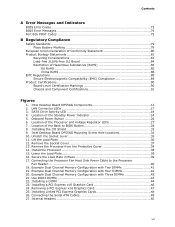
... Installing the I/O Shield 33 9. Remove the Socket Cover 37 13. Remove the Processor from the Protective Cover 38 14. Example Dual Channel Memory Configuration with Four DIMMs 42 20. Use DDR3 DIMMs 43 22. Connecting the Serial ATA Cables 49 27. Lower the Load Plate 39 16.... Location of the Processor and Voltage Regulator LEDs 27 7. Intel Desktop Board DP55KG Mounting Screw Hole Locations 34 10. Example Dual Channel Memory Configuration with Two DIMMs 41 19. Installing a DIMM 44 23. Internal Headers 50 vii Install the ...
... Installing the I/O Shield 33 9. Remove the Socket Cover 37 13. Remove the Processor from the Protective Cover 38 14. Example Dual Channel Memory Configuration with Four DIMMs 42 20. Use DDR3 DIMMs 43 22. Connecting the Serial ATA Cables 49 27. Lower the Load Plate 39 16.... Location of the Processor and Voltage Regulator LEDs 27 7. Intel Desktop Board DP55KG Mounting Screw Hole Locations 34 10. Example Dual Channel Memory Configuration with Two DIMMs 41 19. Installing a DIMM 44 23. Internal Headers 50 vii Install the ...

Product Guide
Page 9
... (304.80 millimeters [12.00 inches] x 243.84 millimeters [9.60 inches]) Support for an Intel® processor in the LGA1156 package • Four 240-pin DDR3 SDRAM Dual Inline Memory Module (DIMM) sockets arranged in two channels • Support for DDR3 1600+ MHz, DDR3 1333 MHz, and DDR3... 1066 MHz DIMMs • Support for non-ECC memory • Support for up to 16 GB of system memory Chipset Intel® P55 Express Chipset consisting of Intel® Desktop Board DP55KG. Table 1. 1 Desktop Board Features This chapter briefly describes the features of...
... (304.80 millimeters [12.00 inches] x 243.84 millimeters [9.60 inches]) Support for an Intel® processor in the LGA1156 package • Four 240-pin DDR3 SDRAM Dual Inline Memory Module (DIMM) sockets arranged in two channels • Support for DDR3 1600+ MHz, DDR3 1333 MHz, and DDR3... 1066 MHz DIMMs • Support for non-ECC memory • Support for up to 16 GB of system memory Chipset Intel® P55 Express Chipset consisting of Intel® Desktop Board DP55KG. Table 1. 1 Desktop Board Features This chapter briefly describes the features of...

Product Guide
Page 10
... RJ-45 back panel connector with integrated status LEDs Wireless Support BIOS Integrated Bluetooth* technology • Intel® Platform Innovation Framework for extensible firmware interface • 16 Mb symmetrical flash memory device • Support for SMBIOS • Intel® Express BIOS Update Power Management • Support for Advanced Configuration and Power Interface (ACPI...
... RJ-45 back panel connector with integrated status LEDs Wireless Support BIOS Integrated Bluetooth* technology • Intel® Platform Innovation Framework for extensible firmware interface • 16 Mb symmetrical flash memory device • Support for SMBIOS • Intel® Express BIOS Update Power Management • Support for Advanced Configuration and Power Interface (ACPI...

Product Guide
Page 15
...pin Double Data Rate 3 (DDR3) SDRAM Dual Inline Memory Module (DIMM) connectors with a voltage rating higher than 4 GB because of BIOS and manual memory tuning. and dual-channel memory interleaving • Unbuffered, non-registered single- If your memory modules do not support SPD, you will see a... notification to configure the memory controller for single- Desktop Board Features Main Memory NOTE To be fully compliant with all applicable Intel ® SDRAM memory specifications, the board should be populated with DIMMs that support the Serial Presence ...
...pin Double Data Rate 3 (DDR3) SDRAM Dual Inline Memory Module (DIMM) connectors with a voltage rating higher than 4 GB because of BIOS and manual memory tuning. and dual-channel memory interleaving • Unbuffered, non-registered single- If your memory modules do not support SPD, you will see a... notification to configure the memory controller for single- Desktop Board Features Main Memory NOTE To be fully compliant with all applicable Intel ® SDRAM memory specifications, the board should be populated with DIMMs that support the Serial Presence ...

Product Guide
Page 23
... to support multiple wake events from the PCI and/or USB buses exceeds power supply capacity, the Desktop Board may lose register settings stored in memory. LAN Wake Capabilities CAUTION For LAN wake capabilities, the 5 V standby line for the power supply must be off. If the computer has a dual-colored power...
... to support multiple wake events from the PCI and/or USB buses exceeds power supply capacity, the Desktop Board may lose register settings stored in memory. LAN Wake Capabilities CAUTION For LAN wake capabilities, the 5 V standby line for the power supply must be off. If the computer has a dual-colored power...
Product Guide
Page 24
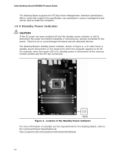
...standby power indicator is still lit, disconnect the power cord before installing or removing any attached devices. Intel Desktop Board DP55KG Product Guide The Desktop Board supports the PCI Bus Power Management Interface Specification. The Desktop...Board, refer to the board. Add-in Figure 4, is lit when there is still present at http://support.intel.com/support/motherboards/desktop/ 24 Failure to wake the computer. +5 V Standby Power Indicator CAUTION If the ... connected to the Technical Product Specification at the memory module sockets and the PCI bus connectors. Figure 4.
...standby power indicator is still lit, disconnect the power cord before installing or removing any attached devices. Intel Desktop Board DP55KG Product Guide The Desktop Board supports the PCI Bus Power Management Interface Specification. The Desktop...Board, refer to the board. Add-in Figure 4, is lit when there is still present at http://support.intel.com/support/motherboards/desktop/ 24 Failure to wake the computer. +5 V Standby Power Indicator CAUTION If the ... connected to the Technical Product Specification at the memory module sockets and the PCI bus connectors. Figure 4.
Product Guide
Page 31
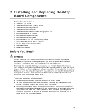
... chapter tells you how to: • Install the I/O shield • Install and remove the Desktop Board • Install and remove a processor • Install and remove memory • Install and remove a PCI Express x16 graphics card • Connect the Serial ATA cables • Connect to the internal headers • Connect to the...
... chapter tells you how to: • Install the I/O shield • Install and remove the Desktop Board • Install and remove a processor • Install and remove memory • Install and remove a PCI Express x16 graphics card • Connect the Serial ATA cables • Connect to the internal headers • Connect to the...

Product Guide
Page 41
...speed and size (see Figure 18) in both Channel A and Channel B. Installing and Replacing Desktop Board Components Installing and Removing System Memory Desktop board DP55KG has four 240-pin DDR3 DIMM sockets arranged as DIMM 0 and DIMM 1 in DIMM 0 (blue) of channels... A and B. Guidelines for Dual Channel Memory Configuration Before installing DIMMs, read and follow these guidelines for dual channel memory configuration. Figure 18. Example Dual Channel Memory Configuration with Two DIMMs 41 NOTE The Intel P55 Express Chipset requires memory to be installed in the Channel A, DIMM 0 ...
...speed and size (see Figure 18) in both Channel A and Channel B. Installing and Replacing Desktop Board Components Installing and Removing System Memory Desktop board DP55KG has four 240-pin DDR3 DIMM sockets arranged as DIMM 0 and DIMM 1 in DIMM 0 (blue) of channels... A and B. Guidelines for Dual Channel Memory Configuration Before installing DIMMs, read and follow these guidelines for dual channel memory configuration. Figure 18. Example Dual Channel Memory Configuration with Two DIMMs 41 NOTE The Intel P55 Express Chipset requires memory to be installed in the Channel A, DIMM 0 ...

Product Guide
Page 42
Intel Desktop Board DP55KG Product Guide If additional memory is to use three DIMMs in a dual-channel configuration, install a matched pair of DIMMs equal in speed and size in single channel memory operation. 42 Figure 19. Install a DIMM equal in speed and total size of the DIMMs ...channels A and B (see Figure 20). Figure 20. Example Dual Channel Memory Configuration with Three DIMMs NOTE All other memory configurations will result in DIMM 0 (blue) and DIMM 1 (black) of channel A. Example Dual Channel Memory Configuration with Four DIMMs Three DIMMs If you want to be used, ...
Intel Desktop Board DP55KG Product Guide If additional memory is to use three DIMMs in a dual-channel configuration, install a matched pair of DIMMs equal in speed and size in single channel memory operation. 42 Figure 19. Install a DIMM equal in speed and total size of the DIMMs ...channels A and B (see Figure 20). Figure 20. Example Dual Channel Memory Configuration with Three DIMMs NOTE All other memory configurations will result in DIMM 0 (blue) and DIMM 1 (black) of channel A. Example Dual Channel Memory Configuration with Four DIMMs Three DIMMs If you want to be used, ...

Product Guide
Page 44
... Figure 22). 8. To install a DIMM, follow these steps: 1. Turn off the computer and disconnect the AC power cord. 3. Installing a DIMM 5. Intel Desktop Board DP55KG Product Guide NOTE For best memory performance, install memory in place. 44 Remove the computer's cover and locate the DIMM sockets (see inset in the PCI Express x16 connector...
... Figure 22). 8. To install a DIMM, follow these steps: 1. Turn off the computer and disconnect the AC power cord. 3. Installing a DIMM 5. Intel Desktop Board DP55KG Product Guide NOTE For best memory performance, install memory in place. 44 Remove the computer's cover and locate the DIMM sockets (see inset in the PCI Express x16 connector...

Product Guide
Page 61
..., plug in , the standby current from the AC power source. 11. Replacing the Battery A coin-cell battery (CR2032) powers the real-time clock and CMOS memory. When the computer is accurate to ± 13 minutes/year at 25 ºC with an incorrect type. Les piles usagées doivent être...
..., plug in , the standby current from the AC power source. 11. Replacing the Battery A coin-cell battery (CR2032) powers the real-time clock and CMOS memory. When the computer is accurate to ± 13 minutes/year at 25 ºC with an incorrect type. Les piles usagées doivent être...
Product Guide
Page 67
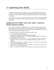
...Navigate to complete the BIOS update. 67 This step is included in an automated update utility that combines the functionality of the Intel® Flash Memory Update Utility and the ease of use of Windows-based installation wizards. Follow the instructions provided in the Windows environment. This chapter... update fails. To update the BIOS with the Intel® Express BIOS Update Utility With the Intel Express BIOS Update utility you can access the BIOS Setup program by either using the Intel Express BIOS Update utility or the Iflash Memory Update utility, and how to a removable USB ...
...Navigate to complete the BIOS update. 67 This step is included in an automated update utility that combines the functionality of the Intel® Flash Memory Update Utility and the ease of use of Windows-based installation wizards. Follow the instructions provided in the Windows environment. This chapter... update fails. To update the BIOS with the Intel® Express BIOS Update Utility With the Intel Express BIOS Update utility you can access the BIOS Setup program by either using the Intel Express BIOS Update utility or the Iflash Memory Update utility, and how to a removable USB ...
Product Guide
Page 68
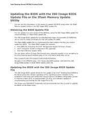
... to CD. The Iflash BIOS update file contains: • New BIOS file (including the Intel® Management Engine Firmware Image) • Intel® Integrator Toolkit Configuration File (optional) • Intel Flash Memory Update Utility You can update to a new version of the BIOS by using either of these... the operating system installed on the Intel World Wide Web site at: http://support.intel.com/support/motherboards/desktop Navigate to remove the BIOS configuration jumper. Updating the BIOS with the ISO Image BIOS Update File or the Iflash Memory Update Utility You can be used ...
... to CD. The Iflash BIOS update file contains: • New BIOS file (including the Intel® Management Engine Firmware Image) • Intel® Integrator Toolkit Configuration File (optional) • Intel Flash Memory Update Utility You can update to a new version of the BIOS by using either of these... the operating system installed on the Intel World Wide Web site at: http://support.intel.com/support/motherboards/desktop Navigate to remove the BIOS configuration jumper. Updating the BIOS with the ISO Image BIOS Update File or the Iflash Memory Update Utility You can be used ...

Product Guide
Page 69
.... The update may not function properly. Updating the BIOS CAUTION Do not interrupt the process or the system may take up to 5 minutes. The Iflash Memory update utility allows you to complete. Download the ISO Image BIOS file. 2. When the "Press ENTER to CD will automatically update your computer before attempting... the CD-ROM drive of uncompressing and writing an ISO image file to CD, burn the data to a blank CD. At the "Welcome to the Intel Desktop Board BIOS Upgrade CD-ROM" page, press any key to upgrade the BIOS using the ISO Image BIOS file: 1. CAUTION Do not power down...
.... The update may not function properly. Updating the BIOS CAUTION Do not interrupt the process or the system may take up to 5 minutes. The Iflash Memory update utility allows you to complete. Download the ISO Image BIOS file. 2. When the "Press ENTER to CD will automatically update your computer before attempting... the CD-ROM drive of uncompressing and writing an ISO image file to CD, burn the data to a blank CD. At the "Welcome to the Intel Desktop Board BIOS Upgrade CD-ROM" page, press any key to upgrade the BIOS using the ISO Image BIOS file: 1. CAUTION Do not power down...

Product Guide
Page 71
...select RAID 0 or RAID 1 (if only two SATA drives are available), RAID 5 and RAID 10 (these options will see the following Intel Matrix Storage Manager option ROM status message on the remaining portion of your volume) and press . 7. ensure that RAID is selected. 4. ...; Matrix Storage Technology NOTE Intel Matrix Storage Technology requires Microsoft Windows 7, Microsoft Windows Vista, or Microsoft Windows XP operating system and SATA hard drives. Assemble your settings by pressing after the Power-On-Self-Test (POST) memory tests begin. 3. In the Intel Matrix Storage Manager option ROM...
...select RAID 0 or RAID 1 (if only two SATA drives are available), RAID 5 and RAID 10 (these options will see the following Intel Matrix Storage Manager option ROM status message on the remaining portion of your volume) and press . 7. ensure that RAID is selected. 4. ...; Matrix Storage Technology NOTE Intel Matrix Storage Technology requires Microsoft Windows 7, Microsoft Windows Vista, or Microsoft Windows XP operating system and SATA hard drives. Assemble your settings by pressing after the Power-On-Self-Test (POST) memory tests begin. 3. In the Intel Matrix Storage Manager option ROM...
Product Guide
Page 73
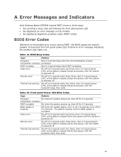
...beeps and pause) until the system is powered off for 0.5 seconds. initialization complete POST complete On when the system powers up , then off . Memory error On-off (0.5 seconds each ) three times, then 3.0 second pause (off), entire pattern repeats (blinks and pause) until the system is ...panel power LED • By displaying an error message on for 0.5 seconds, then off . Table 15. A Error Messages and Indicators Intel Desktop Board DP55KG reports POST errors in progress Off when the update begins, then on the monitor • By displaying diagnostic progress codes ...
...beeps and pause) until the system is powered off for 0.5 seconds. initialization complete POST complete On when the system powers up , then off . Memory error On-off (0.5 seconds each ) three times, then 3.0 second pause (off), entire pattern repeats (blinks and pause) until the system is ...panel power LED • By displaying an error message on for 0.5 seconds, then off . Table 15. A Error Messages and Indicators Intel Desktop Board DP55KG reports POST errors in progress Off when the update begins, then on the monitor • By displaying diagnostic progress codes ...

Product Guide
Page 74
... operation. Table 16 gives an explanation of memory in each channel. 74 The firmware has detected that the system date/time has not been set. The firmware has detected that a CMOS Checksum Error occurred. The firmware has detected that a CMOS battery failure occurred. Intel Desktop Board DP55KG Product Guide BIOS Error Messages...
... operation. Table 16 gives an explanation of memory in each channel. 74 The firmware has detected that the system date/time has not been set. The firmware has detected that a CMOS Checksum Error occurred. The firmware has detected that a CMOS battery failure occurred. Intel Desktop Board DP55KG Product Guide BIOS Error Messages...
Product Guide
Page 76
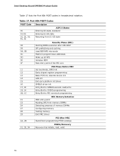
...Entry/Exit to CK505 programming Entry/Exit to PEI overclock programming MEC Memory Detection 21 MRC entry point 23 Reading SPD from memory DIMMs 24 Detecting presence of memory DIMMs 27 Configuring memory 28 Testing memory 29 Exit MRC driver 2A, 2B PEI After MRC Start/finish ...programming MTRR settings 31, 33, 34 PEIMs/Recovery Recovery has initiate, load, valid 76 Intel Desktop Board DP55KG Product...
...Entry/Exit to CK505 programming Entry/Exit to PEI overclock programming MEC Memory Detection 21 MRC entry point 23 Reading SPD from memory DIMMs 24 Detecting presence of memory DIMMs 27 Configuring memory 28 Testing memory 29 Exit MRC driver 2A, 2B PEI After MRC Start/finish ...programming MTRR settings 31, 33, 34 PEIMs/Recovery Recovery has initiate, load, valid 76 Intel Desktop Board DP55KG Product...


