
Product Guide
Page 5
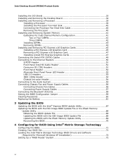
Contents 1 Desktop Board Features Supported Operating Systems 11 Desktop Board Components 12 Processor ...14 Main Memory...15 Intel® P55 Express Chipset 16 Audio Subsystem 16 LAN Subsystem 16 Bluetooth* Technology Support 17 USB 2.0 Support 17 Serial ATA Support 18 Legacy I/O ......Support 25 WAKE# Signal Wake-up Support 25 Wake from Consumer IR 25 ENERGY STAR*, e-Standby, and EuP Compliance 25 Onboard Power Button 26 Processor and Voltage Regulator LEDs 27 Back to BIOS Button 28 Speaker...29 Battery ...29 Real-Time Clock 29 2 Installing and Replacing Desktop Board Components...
Contents 1 Desktop Board Features Supported Operating Systems 11 Desktop Board Components 12 Processor ...14 Main Memory...15 Intel® P55 Express Chipset 16 Audio Subsystem 16 LAN Subsystem 16 Bluetooth* Technology Support 17 USB 2.0 Support 17 Serial ATA Support 18 Legacy I/O ......Support 25 WAKE# Signal Wake-up Support 25 Wake from Consumer IR 25 ENERGY STAR*, e-Standby, and EuP Compliance 25 Onboard Power Button 26 Processor and Voltage Regulator LEDs 27 Back to BIOS Button 28 Speaker...29 Battery ...29 Real-Time Clock 29 2 Installing and Replacing Desktop Board Components...
Product Guide
Page 6
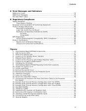
Intel Desktop Board DP55KG Product Guide Installing the I/O Shield 33 Installing and Removing the Desktop Board 34 Installing and Removing a Processor 35 Installing a Processor 35 Installing the Processor Fan Heat Sink 40 Connecting the Processor Fan Heat Sink Cable 40 Removing the Processor 40 Installing and Removing System ...Setting the BIOS Configuration Jumper 59 Clearing Passwords 60 Replacing the Battery 61 3 Updating the BIOS Updating the BIOS with the Intel® Express BIOS Update Utility 67 Updating the BIOS with the ISO Image BIOS Update File or the Iflash Memory Update...
Intel Desktop Board DP55KG Product Guide Installing the I/O Shield 33 Installing and Removing the Desktop Board 34 Installing and Removing a Processor 35 Installing a Processor 35 Installing the Processor Fan Heat Sink 40 Connecting the Processor Fan Heat Sink Cable 40 Removing the Processor 40 Installing and Removing System ...Setting the BIOS Configuration Jumper 59 Clearing Passwords 60 Replacing the Battery 61 3 Updating the BIOS Updating the BIOS with the Intel® Express BIOS Update Utility 67 Updating the BIOS with the ISO Image BIOS Update File or the Iflash Memory Update...
Product Guide
Page 7
... 22. Installing a PCI Express x16 Graphics Card 46 24. Onboard Power Button 26 6. Install the Processor 38 15. Example Dual Channel Memory Configuration with Two DIMMs 41 19. Installing Linked PCI Express Graphics Cards 48 26. Intel Desktop Board DP55KG Mounting Screw Hole Locations 34 10. Remove the Socket Cover 37 13...
... 22. Installing a PCI Express x16 Graphics Card 46 24. Onboard Power Button 26 6. Install the Processor 38 15. Example Dual Channel Memory Configuration with Two DIMMs 41 19. Installing Linked PCI Express Graphics Cards 48 26. Intel Desktop Board DP55KG Mounting Screw Hole Locations 34 10. Remove the Socket Cover 37 13...

Product Guide
Page 9
... Support for multiple PCI Express* 2.0 graphics cards • Independent multi-streaming 8-channel (7.1) audio and 2-channel audio subsystem, featuring: ― Intel® High Definition (Intel® HD) Audio interface ― Realtek* ALC889 codec • HD Audio front panel header • Onboard 4-pin S/PDIF out connector... 1600+ MHz, DDR3 1333 MHz, and DDR3 1066 MHz DIMMs • Support for non-ECC memory • Support for an Intel® processor in the LGA1156 package • Four 240-pin DDR3 SDRAM Dual Inline Memory Module (DIMM) sockets arranged in optical connectors •...
... Support for multiple PCI Express* 2.0 graphics cards • Independent multi-streaming 8-channel (7.1) audio and 2-channel audio subsystem, featuring: ― Intel® High Definition (Intel® HD) Audio interface ― Realtek* ALC889 codec • HD Audio front panel header • Onboard 4-pin S/PDIF out connector... 1600+ MHz, DDR3 1333 MHz, and DDR3 1066 MHz DIMMs • Support for non-ECC memory • Support for an Intel® processor in the LGA1156 package • Four 240-pin DDR3 SDRAM Dual Inline Memory Module (DIMM) sockets arranged in optical connectors •...

Product Guide
Page 13
...Express 2.0 x16 connector (x8/x16 electrical) Battery Back panel connectors Vertical USB connector 12 V processor core voltage connector (2 x 4 pin) Processor fan header Processor LED Voltage regulator LED Processor socket POST code LED display DDR3 Channel A, DIMM 0 and DIMM 1 sockets DDR3 Channel ... configuration jumper block Serial ATA connectors Chassis intrusion header BlueTooth* module Speaker Auxiliary PCI Express graphics power connector (SATA-style) Auxiliary chassis fan header 13 Intel Desktop Board DP55KG Components Label A B C D E F G H I J K L M N O P Q R S T U V W X Y Z AA BB CC ...
...Express 2.0 x16 connector (x8/x16 electrical) Battery Back panel connectors Vertical USB connector 12 V processor core voltage connector (2 x 4 pin) Processor fan header Processor LED Voltage regulator LED Processor socket POST code LED display DDR3 Channel A, DIMM 0 and DIMM 1 sockets DDR3 Channel ... configuration jumper block Serial ATA connectors Chassis intrusion header BlueTooth* module Speaker Auxiliary PCI Express graphics power connector (SATA-style) Auxiliary chassis fan header 13 Intel Desktop Board DP55KG Components Label A B C D E F G H I J K L M N O P Q R S T U V W X Y Z AA BB CC ...
Product Guide
Page 14
... Product Guide Online Support For more information on supported processors for Intel Desktop Board DP55KG http://www.intel.com/products/motherboard/DP55KG /index.htm • Supported processors http://processormatch.intel.com • Chipset information http://www.intel.com/products/desktop/chipsets/inde x.htm • BIOS and driver updates http://downloadcenter.intel.com/ • Integration information http://www...
... Product Guide Online Support For more information on supported processors for Intel Desktop Board DP55KG http://www.intel.com/products/motherboard/DP55KG /index.htm • Supported processors http://processormatch.intel.com • Chipset information http://www.intel.com/products/desktop/chipsets/inde x.htm • BIOS and driver updates http://downloadcenter.intel.com/ • Integration information http://www...

Product Guide
Page 15
...Dual Inline Memory Module (DIMM) connectors with gold-plated contacts arranged in graphics cards and other system resources. 15 Individual results may damage the processor. • Non-ECC DDR3 memory • Serial Presence Detect (SPD) memory only • Up to 16 GB maximum total system memory...with DIMMs that support the Serial Presence Detect (SPD) data structure. Desktop Board Features Main Memory NOTE To be fully compliant with all applicable Intel ® SDRAM memory specifications, the board should be populated with a voltage rating higher than 4 GB because of the memory used by ...
...Dual Inline Memory Module (DIMM) connectors with gold-plated contacts arranged in graphics cards and other system resources. 15 Individual results may damage the processor. • Non-ECC DDR3 memory • Serial Presence Detect (SPD) memory only • Up to 16 GB maximum total system memory...with DIMMs that support the Serial Presence Detect (SPD) data structure. Desktop Board Features Main Memory NOTE To be fully compliant with all applicable Intel ® SDRAM memory specifications, the board should be populated with a voltage rating higher than 4 GB because of the memory used by ...

Product Guide
Page 21
... removed. Chassis Intrusion The board supports a chassis security feature that can adjust fan speed Intel® Precision Cooling Technology Intel Precision Cooling Technology automatically adjusts processor fan speed based on the processor temperature and adjusts chassis fan speeds based on the Desktop Board. See Figure 27 for ... chassis intrusion header on the internal system temperature. Desktop Board Features Hardware Management The hardware management features of Intel Desktop Board DP55KG enable the board to be connected to detect levels above and below acceptable values •...
... removed. Chassis Intrusion The board supports a chassis security feature that can adjust fan speed Intel® Precision Cooling Technology Intel Precision Cooling Technology automatically adjusts processor fan speed based on the processor temperature and adjusts chassis fan speeds based on the Desktop Board. See Figure 27 for ... chassis intrusion header on the internal system temperature. Desktop Board Features Hardware Management The hardware management features of Intel Desktop Board DP55KG enable the board to be connected to detect levels above and below acceptable values •...

Product Guide
Page 23
...* frame, it asserts a wake-up signal that can damage the power supply and/or effect ACPI S3 sleep state functionality. The Desktop Board has a 4-pin processor fan header and three 4-pin chassis fan headers.
...* frame, it asserts a wake-up signal that can damage the power supply and/or effect ACPI S3 sleep state functionality. The Desktop Board has a 4-pin processor fan header and three 4-pin chassis fan headers.

Product Guide
Page 27
Location of the board's voltage regulation circuitry and the processor: • The Processor LED (Figure 6, A) indicates an elevated temperature on the processor that could affect performance. • The Voltage Regulator LED (Figure 6, B) indicates an elevated temperature in the processor voltage regulator circuit that could affect performance. Figure 6. Desktop Board Features Processor and Voltage Regulator LEDs The Desktop Board contains two red LEDs (see Figure 6) that indicate the status of the Processor and Voltage Regulator LEDs 27
Location of the board's voltage regulation circuitry and the processor: • The Processor LED (Figure 6, A) indicates an elevated temperature on the processor that could affect performance. • The Voltage Regulator LED (Figure 6, B) indicates an elevated temperature in the processor voltage regulator circuit that could affect performance. Figure 6. Desktop Board Features Processor and Voltage Regulator LEDs The Desktop Board contains two red LEDs (see Figure 6) that indicate the status of the Processor and Voltage Regulator LEDs 27
Product Guide
Page 31
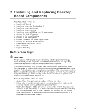
... Replacing Desktop Board Components This chapter tells you how to: • Install the I/O shield • Install and remove the Desktop Board • Install and remove a processor • Install and remove memory • Install and remove a PCI Express x16 graphics card • Connect the Serial ATA cables • Connect to the internal...
... Replacing Desktop Board Components This chapter tells you how to: • Install the I/O shield • Install and remove the Desktop Board • Install and remove a processor • Install and remove memory • Install and remove a PCI Express x16 graphics card • Connect the Serial ATA cables • Connect to the internal...

Product Guide
Page 32
...8226; Sharp pins on printed circuit assemblies • Rough edges and sharp corners on the chassis • Hot components (such as processors, voltage regulators, and heat sinks) • Damage to qualified technical personnel. For information about the Desktop Board's regulatory compliance, ... Requirements Read and follow these instructions or the instructions for the chassis are inconsistent with the chassis and associated modules. Intel Desktop Board DP55KG Product Guide Installation Precautions When you can ensure that your safety risk and the possibility of noncompliance with...
...8226; Sharp pins on printed circuit assemblies • Rough edges and sharp corners on the chassis • Hot components (such as processors, voltage regulators, and heat sinks) • Damage to qualified technical personnel. For information about the Desktop Board's regulatory compliance, ... Requirements Read and follow these instructions or the instructions for the chassis are inconsistent with the chassis and associated modules. Intel Desktop Board DP55KG Product Guide Installation Precautions When you can ensure that your safety risk and the possibility of noncompliance with...

Product Guide
Page 35
... be lit (see Figure 4 on page 31. 2. Installing and Replacing Desktop Board Components Installing and Removing a Processor Instructions on how to do so could damage the processor and the board. Installing a Processor CAUTION Before installing or removing a processor, make sure the AC power has been removed by pushing the lever down and away from...
... be lit (see Figure 4 on page 31. 2. Installing and Replacing Desktop Board Components Installing and Removing a Processor Instructions on how to do so could damage the processor and the board. Installing a Processor CAUTION Before installing or removing a processor, make sure the AC power has been removed by pushing the lever down and away from...

Product Guide
Page 37
... front edge of the cover and resting your index finger on the rear grip (Figure 12, A). Always replace the socket cover if you remove the processor from the socket (Figure 12, B). Remove the Socket Cover 37 save it for possible future use. Installing and Replacing Desktop Board Components 4.
... front edge of the cover and resting your index finger on the rear grip (Figure 12, A). Always replace the socket cover if you remove the processor from the socket (Figure 12, B). Remove the Socket Cover 37 save it for possible future use. Installing and Replacing Desktop Board Components 4.

Product Guide
Page 38
... align your fingers with the posts on the socket (Figure 14, C). Remove the Processor from the socket. Intel Desktop Board DP55KG Product Guide 5. Always replace the processor cover if you remove the processor from the Protective Cover 6. Make sure that the processor Pin 1 indicator (gold triangle) is aligned with the Pin 1 chamfer on the socket...
... align your fingers with the posts on the socket (Figure 14, C). Remove the Processor from the socket. Intel Desktop Board DP55KG Product Guide 5. Always replace the processor cover if you remove the processor from the Protective Cover 6. Make sure that the processor Pin 1 indicator (gold triangle) is aligned with the Pin 1 chamfer on the socket...

Product Guide
Page 39
Installing and Replacing Desktop Board Components 7. Figure 16. Lower the load plate over the processor while leaving the socket lever in Place 39 Lower the Load Plate 8. Secure the Load Plate in the open position (Figure 15). Figure 15. Latch the socket lever under the shoulder screw cap as the lever is lowered (Figure 16, A). Lower the socket lever (Figure 16, B) while making sure that the front edge of the load plate slides under the load plate tab (Figure 16, C, D).
Installing and Replacing Desktop Board Components 7. Figure 16. Lower the load plate over the processor while leaving the socket lever in Place 39 Lower the Load Plate 8. Secure the Load Plate in the open position (Figure 15). Figure 15. Latch the socket lever under the shoulder screw cap as the lever is lowered (Figure 16, A). Lower the socket lever (Figure 16, B) while making sure that the front edge of the load plate slides under the load plate tab (Figure 16, C, D).

Product Guide
Page 40
...to the Processor Fan Header Removing the Processor For instructions on how to attach the processor fan heat sink to the Desktop Board, refer to the boxed processor manual or boxed thermal solution manual. Intel Desktop Board DP55KG Product Guide Installing the Processor Fan Heat Sink Intel Desktop Board... DP55KG has mounting holes for a processor fan heat sink. A fan with a 4-pin connector as ...
...to the Processor Fan Header Removing the Processor For instructions on how to attach the processor fan heat sink to the Desktop Board, refer to the boxed processor manual or boxed thermal solution manual. Intel Desktop Board DP55KG Product Guide Installing the Processor Fan Heat Sink Intel Desktop Board... DP55KG has mounting holes for a processor fan heat sink. A fan with a 4-pin connector as ...

Product Guide
Page 58
... the system chassis. In order to the onboard Bluetooth module. Attach the connector on page 31. 2. Figure 31. Connect the 12 V processor core voltage power supply cable to the mating connector on page 31. 2. Remove the paper backing from the antenna (Figure 31, C) and...to the 2 x 12 pin connector (Figure 30, C). 4. Observe the precautions in "Before You Begin" on the Bluetooth module (Figure 31, A). 3. Intel Desktop Board DP55KG Product Guide 1. If additional power is provided with Bluetooth-enabled devices, you must connect the antenna to communicate with the desktop board...
... the system chassis. In order to the onboard Bluetooth module. Attach the connector on page 31. 2. Figure 31. Connect the 12 V processor core voltage power supply cable to the mating connector on page 31. 2. Remove the paper backing from the antenna (Figure 31, C) and...to the 2 x 12 pin connector (Figure 30, C). 4. Observe the precautions in "Before You Begin" on the Bluetooth module (Figure 31, A). 3. Intel Desktop Board DP55KG Product Guide 1. If additional power is provided with Bluetooth-enabled devices, you must connect the antenna to communicate with the desktop board...
Product Guide
Page 73
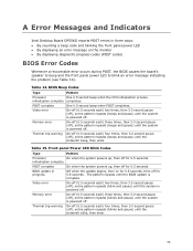
...(off), entire pattern repeats (blink and pause) until the sixteenth blink, then ends. 73 Front-panel Power LED Blink Codes Type Pattern Processor On when the system powers up , then off ), entire pattern repeats (blinks and pause) until the system is powered off . Video ...each ) four times, then 3.0 second pause (off . BIOS Beep Codes Type Pattern Processor One 0.5 second beep when the CPU initialization process initialization complete completes. A Error Messages and Indicators Intel Desktop Board DP55KG reports POST errors in progress Off when the update begins, then on ...
...(off), entire pattern repeats (blink and pause) until the sixteenth blink, then ends. 73 Front-panel Power LED Blink Codes Type Pattern Processor On when the system powers up , then off ), entire pattern repeats (blinks and pause) until the system is powered off . Video ...each ) four times, then 3.0 second pause (off . BIOS Beep Codes Type Pattern Processor One 0.5 second beep when the CPU initialization process initialization complete completes. A Error Messages and Indicators Intel Desktop Board DP55KG reports POST errors in progress Off when the update begins, then on ...

Product Guide
Page 74
... thermal event (overheating). BIOS Error Messages Error Message PROCESSOR_THERMAL_TRIP_ERROR CMOS_BATTERY_ERROR CMOS_CHECKSUM_ERROR CMOS_TIMER_ERROR MEMORY_SIZE_DECREASE_ERROR INTRUDER_DETECTION_ERROR SPD_TOLER_ERROR MEM_OPTIMAL_ERROR Explanation Processor was opened. The firmware has detected that a CMOS battery failure occurred. The firmware has detected that ... system chassis was previously shutdown due to the amount of memory installed in Channel B. Table 16. Intel Desktop Board DP55KG Product Guide BIOS Error Messages When a recoverable error occurs during the POST, the...
... thermal event (overheating). BIOS Error Messages Error Message PROCESSOR_THERMAL_TRIP_ERROR CMOS_BATTERY_ERROR CMOS_CHECKSUM_ERROR CMOS_TIMER_ERROR MEMORY_SIZE_DECREASE_ERROR INTRUDER_DETECTION_ERROR SPD_TOLER_ERROR MEM_OPTIMAL_ERROR Explanation Processor was opened. The firmware has detected that a CMOS battery failure occurred. The firmware has detected that ... system chassis was previously shutdown due to the amount of memory installed in Channel B. Table 16. Intel Desktop Board DP55KG Product Guide BIOS Error Messages When a recoverable error occurs during the POST, the...


