
Product Specification
Page 5
... 1.4 Processor 14 1.5 Intel® Q67 Express Chipset 15 1.6 System Memory 15 1.6.1 Memory Configurations 16 1.7 Graphics Subsystem 18 1.7.1 Integrated Graphics 18 1.7.2 PCI Express x16 Graphics 19 1.8 USB 19 1.9 SATA Interfaces 20 1.10 Legacy I/O Controller 21 1.10.1 Serial Port 21 1.11 Audio Subsystem 22 1.11.1 Audio Subsystem Software 22 1.11.2 Audio Headers and Connectors 22 1.12 LAN Subsystem 24 1.12.1 Intel® 82579LM Gigabit Ethernet Controller 24 1.12.2 LAN Subsystem Software 24 1.12.3 RJ-45 LAN Connector with Integrated LEDs 25 1.13 Real-Time Clock...
... 1.4 Processor 14 1.5 Intel® Q67 Express Chipset 15 1.6 System Memory 15 1.6.1 Memory Configurations 16 1.7 Graphics Subsystem 18 1.7.1 Integrated Graphics 18 1.7.2 PCI Express x16 Graphics 19 1.8 USB 19 1.9 SATA Interfaces 20 1.10 Legacy I/O Controller 21 1.10.1 Serial Port 21 1.11 Audio Subsystem 22 1.11.1 Audio Subsystem Software 22 1.11.2 Audio Headers and Connectors 22 1.12 LAN Subsystem 24 1.12.1 Intel® 82579LM Gigabit Ethernet Controller 24 1.12.2 LAN Subsystem Software 24 1.12.3 RJ-45 LAN Connector with Integrated LEDs 25 1.13 Real-Time Clock...

Product Specification
Page 6
... System Management BIOS (SMBIOS 65 3.3 Legacy USB Support 65 3.4 BIOS Updates 66 3.4.1 Language Support 66 3.4.2 Custom Splash Screen 67 3.5 BIOS Recovery 67 3.6 Boot Options 68 3.6.1 Optical Drive Boot 68 3.6.2 Network Boot 68 3.6.3 Booting Without Attached Devices 68 3.6.4 Changing the Default Boot Device During POST 68 3.7 Hard Disk Drive Password Security Feature 69 3.8 BIOS Security Features 70 4 Error Messages and Beep Codes 4.1 Speaker 73 4.2 BIOS Beep Codes 73 4.3 Front-panel Power LED Blink Codes 74 4.4 BIOS Error Messages 74 4.5 Port 80h POST Codes 75 5 Regulatory...
... System Management BIOS (SMBIOS 65 3.3 Legacy USB Support 65 3.4 BIOS Updates 66 3.4.1 Language Support 66 3.4.2 Custom Splash Screen 67 3.5 BIOS Recovery 67 3.6 Boot Options 68 3.6.1 Optical Drive Boot 68 3.6.2 Network Boot 68 3.6.3 Booting Without Attached Devices 68 3.6.4 Changing the Default Boot Device During POST 68 3.7 Hard Disk Drive Password Security Feature 69 3.8 BIOS Security Features 70 4 Error Messages and Beep Codes 4.1 Speaker 73 4.2 BIOS Beep Codes 73 4.3 Front-panel Power LED Blink Codes 74 4.4 BIOS Error Messages 74 4.5 Port 80h POST Codes 75 5 Regulatory...

Product Specification
Page 7
... Audio Header for a One-Color Power LED 52 23. Chassis Intrusion Header 49 18. Main Power Connector 50 21. Alternate Front Panel Power LED Header 52 24. Back Panel Audio Connector Options 23 5. Back Panel Connectors 44 10. Location of Pressing the Power Switch 34 6. Localized High Temperature Zones 61 Tables 1. System Memory Map 43 9. SATA Connectors 48 17. BIOS Setup Configuration Jumper Settings 55 25. Memory Channel and DIMM Configuration 17 4. Thermal Sensors and Fan Headers 27 7. Component-side Connectors and Headers 45 11. Intel MEBX Reset Header...
... Audio Header for a One-Color Power LED 52 23. Chassis Intrusion Header 49 18. Main Power Connector 50 21. Alternate Front Panel Power LED Header 52 24. Back Panel Audio Connector Options 23 5. Back Panel Connectors 44 10. Location of Pressing the Power Switch 34 6. Localized High Temperature Zones 61 Tables 1. System Memory Map 43 9. SATA Connectors 48 17. BIOS Setup Configuration Jumper Settings 55 25. Memory Channel and DIMM Configuration 17 4. Thermal Sensors and Fan Headers 27 7. Component-side Connectors and Headers 45 11. Intel MEBX Reset Header...
Product Specification
Page 8
Intel Desktop Board DQ67EP Technical Product Specification 28. Master Key and User Hard Drive Password Functions 69 35. BIOS Error Messages 74 39. Safety Standards 81 43. Front-panel Power LED Blink Codes 74 38. BIOS Beep Codes 73 37. Port 80h POST Codes 76 41. Regulatory Compliance Marks 89 viii Acceptable Drives/Media Types for Components 61 29. EMC Regulations 85 44. Supervisor and User Password Functions 71 36. Port 80h POST Code Ranges 75 40. Environmental Specifications 62...
Intel Desktop Board DQ67EP Technical Product Specification 28. Master Key and User Hard Drive Password Functions 69 35. BIOS Error Messages 74 39. Safety Standards 81 43. Front-panel Power LED Blink Codes 74 38. BIOS Beep Codes 73 37. Port 80h POST Codes 76 41. Regulatory Compliance Marks 89 viii Acceptable Drives/Media Types for Components 61 29. EMC Regulations 85 44. Supervisor and User Password Functions 71 36. Port 80h POST Code Ranges 75 40. Environmental Specifications 62...

Product Specification
Page 10
Intel Desktop Board DQ67EP Technical Product Specification Table 1. Feature Summary (continued) Peripheral Interfaces Legacy I/O Control BIOS Instantly Available PC Technology • Twelve USB ports: ― Two USB 3.0 ports are implemented with stacked back panel connectors (blue) ― Four USB 2.0 ports are implemented with stacked back panel connectors (black) ― Six USB 2.0 front panel ports are implemented through three dual-port internal headers • Six SATA interfaces through the Intel Q67 Express Chipset with Intel® Rapid Storage Technology RAID support: ― ...
Intel Desktop Board DQ67EP Technical Product Specification Table 1. Feature Summary (continued) Peripheral Interfaces Legacy I/O Control BIOS Instantly Available PC Technology • Twelve USB ports: ― Two USB 3.0 ports are implemented with stacked back panel connectors (blue) ― Four USB 2.0 ports are implemented with stacked back panel connectors (black) ― Six USB 2.0 front panel ports are implemented through three dual-port internal headers • Six SATA interfaces through the Intel Q67 Express Chipset with Intel® Rapid Storage Technology RAID support: ― ...

Product Specification
Page 14
.../support?iid=hdr+support http://ark.intel.com Supported processors Chipset information BIOS and driver updates Tested memory Integration information http://processormatch.intel.com http://www.intel.com/products/desktop/chipsets/index.htm http://downloadcenter.intel.com http://www.intel.com/support/motherboards/desktop/sb/CS025414.htm http://www.intel.com/support/go/buildit 1.4 Processor The board is designed to ) the following: • No floppy drive connector • No PS/2 connector • No Parallel ATA (PATA) IDE drive connector 1.3 Online Support...
.../support?iid=hdr+support http://ark.intel.com Supported processors Chipset information BIOS and driver updates Tested memory Integration information http://processormatch.intel.com http://www.intel.com/products/desktop/chipsets/index.htm http://downloadcenter.intel.com http://www.intel.com/support/motherboards/desktop/sb/CS025414.htm http://www.intel.com/support/go/buildit 1.4 Processor The board is designed to ) the following: • No floppy drive connector • No PS/2 connector • No Parallel ATA (PATA) IDE drive connector 1.3 Online Support...

Product Specification
Page 15
... board has specific requirements for optimum performance. For information about The Intel Q67 Express chipset Resources used by the chipset Refer to http://www.intel.com/products/desktop/chipsets/index.htm Chapter 2 1.6 System Memory The board has two DIMM sockets and supports the following memory features: • Two independent memory channels with interleaved mode support • Supports 1.2 V - 1.8 V DIMM memory voltage • Support for the board's I/O paths. The PCH is installed, the BIOS will attempt to the processor...
... board has specific requirements for optimum performance. For information about The Intel Q67 Express chipset Resources used by the chipset Refer to http://www.intel.com/products/desktop/chipsets/index.htm Chapter 2 1.6 System Memory The board has two DIMM sockets and supports the following memory features: • Two independent memory channels with interleaved mode support • Supports 1.2 V - 1.8 V DIMM memory voltage • Support for the board's I/O paths. The PCH is installed, the BIOS will attempt to the processor...

Product Specification
Page 16
.... If different speed DIMMs are used between channels, the slowest memory timing will be used . Technology and device width can vary from one row of memory organization: • Dual channel (Interleaved) mode. Intel Desktop Board DQ67EP Technical Product Specification Table 3 lists the supported DIMM configurations. Memory Configuration examples Refer to : http://support.intel.com/support/motherboards/desktop/sb/CS025414.htm 1.6.1 Memory Configurations The Intel Core i7, Intel Core i5, Intel Core i3, and Intel Pentium processors support the following types of SDRAM).
.... If different speed DIMMs are used between channels, the slowest memory timing will be used . Technology and device width can vary from one row of memory organization: • Dual channel (Interleaved) mode. Intel Desktop Board DQ67EP Technical Product Specification Table 3 lists the supported DIMM configurations. Memory Configuration examples Refer to : http://support.intel.com/support/motherboards/desktop/sb/CS025414.htm 1.6.1 Memory Configurations The Intel Core i7, Intel Core i5, Intel Core i3, and Intel Pentium processors support the following types of SDRAM).

Product Specification
Page 19
... super-speed capable. The USB 3.0 ports are provided by the NEC* UPD720200 controller. Product Description 1.7.2 PCI Express x16 Graphics The Intel Core i7, Intel Core i5, Intel Core i3, and Intel Pentium processors in an LGA1155 socket support discrete add in graphics cards through three internal headers All 12 USB ports are connected to the SuperSpeed USB 3.0 ports (blue) during installation due to the lack of native USB 3.0 driver support from the operating system. The Intel Q67 Express Chipset provides the USB controller for full-speed devices...
... super-speed capable. The USB 3.0 ports are provided by the NEC* UPD720200 controller. Product Description 1.7.2 PCI Express x16 Graphics The Intel Core i7, Intel Core i5, Intel Core i3, and Intel Pentium processors in an LGA1155 socket support discrete add in graphics cards through three internal headers All 12 USB ports are connected to the SuperSpeed USB 3.0 ports (blue) during installation due to the lack of native USB 3.0 driver support from the operating system. The Intel Q67 Express Chipset provides the USB controller for full-speed devices...

Product Specification
Page 20
... to install separate RAID drivers using the Windows* XP, Windows Vista*, and Windows 7* operating systems. For more information about The location of the SATA connectors Refer to Figure 10, page 45 1.9.1.1 Serial ATA RAID The board supports the Intel Rapid Storage Technology (Intel RST) which support one device per connector: • Two internal SATA 6 Gb/s ports (blue) • Two internal SATA 3 Gb/s ports (black) • Two backpanel eSATA 3 Gb/s ports for external connectivity (red) The PCH provides independent SATA ports with...
... to install separate RAID drivers using the Windows* XP, Windows Vista*, and Windows 7* operating systems. For more information about The location of the SATA connectors Refer to Figure 10, page 45 1.9.1.1 Serial ATA RAID The board supports the Intel Rapid Storage Technology (Intel RST) which support one device per connector: • Two internal SATA 6 Gb/s ports (blue) • Two internal SATA 3 Gb/s ports (black) • Two backpanel eSATA 3 Gb/s ports for external connectivity (red) The PCH provides independent SATA ports with...

Product Specification
Page 31
The maximum resolution supported by KVM Remote Control is 1920 x 1200. If using simultaneous integrated graphics and add-in PCI Express Graphics, Integrated Graphics Device (IGD) must be set as Primary Video Device in the operating system for POST information to be set as the Primary Video Device in the BIOS Setup in • Intel® Control Center • Intel® Management and Security Status Application For information about Intel Active Management Technology (Intel AMT...
The maximum resolution supported by KVM Remote Control is 1920 x 1200. If using simultaneous integrated graphics and add-in PCI Express Graphics, Integrated Graphics Device (IGD) must be set as Primary Video Device in the operating system for POST information to be set as the Primary Video Device in the BIOS Setup in • Intel® Control Center • Intel® Management and Security Status Application For information about Intel Active Management Technology (Intel AMT...
Product Specification
Page 53
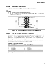
Connection Diagram for Front Panel USB Headers 2.2.2.7 Low Pin Count (LPC) Debug Connector During the POST, the BIOS generates diagnostic progress codes (POST codes) to the USB 2.0 specification for high-speed USB devices. The POST card can interface with the Low Pin Count (LPC) Debug connector. If the POST fails, execution stops and the last POST code generated is useful for the front panel USB headers. Displaying the POST codes requires a POST card that conforms to I/O port 80h. LPC Debug Connector Pin Signal Name Pin 1 VCC3 2 3 PLTRST_N 4 5 LAD0/FWH0...
Connection Diagram for Front Panel USB Headers 2.2.2.7 Low Pin Count (LPC) Debug Connector During the POST, the BIOS generates diagnostic progress codes (POST codes) to the USB 2.0 specification for high-speed USB devices. The POST card can interface with the Low Pin Count (LPC) Debug connector. If the POST fails, execution stops and the last POST code generated is useful for the front panel USB headers. Displaying the POST codes requires a POST card that conforms to I/O port 80h. LPC Debug Connector Pin Signal Name Pin 1 VCC3 2 3 PLTRST_N 4 5 LAD0/FWH0...
Product Specification
Page 55
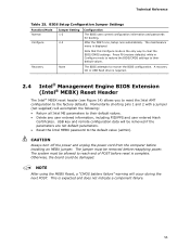
.... • Reset the Intel MEBX password to their default values. BIOS Setup Configuration Jumper Settings Function/Mode Normal Configure Jumper Setting 1-2 2-3 Configuration The BIOS uses current configuration information and passwords for booting. NOTE After using the MEBX Reset, a "CMOS battery failure" warning will be damaged. This is displayed. The maintenance menu is expected and does not indicate a component failure. 55 Note that this Configure mode is complete. Technical Reference Table 25. Momentarily shorting pins 1 and 2 with a jumper (not supplied) will...
.... • Reset the Intel MEBX password to their default values. BIOS Setup Configuration Jumper Settings Function/Mode Normal Configure Jumper Setting 1-2 2-3 Configuration The BIOS uses current configuration information and passwords for booting. NOTE After using the MEBX Reset, a "CMOS battery failure" warning will be damaged. This is displayed. The maintenance menu is expected and does not indicate a component failure. 55 Note that this Configure mode is complete. Technical Reference Table 25. Momentarily shorting pins 1 and 2 with a jumper (not supplied) will...

Product Specification
Page 63
... BIOS displays a message during POST identifying the type of utilities. The BIOS Setup program is accessed by pressing the key after the Power-On Self-Test (POST) memory test begins and before booting as SWQ6710H.86A. The menu bar is in configure mode. Please verify Chipset-SATA Mode settings before the operating system boot begins. 3 Overview of BIOS Features 3.1 Introduction The board uses an Intel BIOS that is stored in a 64 Mbit (8,192 KB) Serial Peripheral Interface Flash Memory...
... BIOS displays a message during POST identifying the type of utilities. The BIOS Setup program is accessed by pressing the key after the Power-On Self-Test (POST) memory test begins and before booting as SWQ6710H.86A. The menu bar is in configure mode. Please verify Chipset-SATA Mode settings before the operating system boot begins. 3 Overview of BIOS Features 3.1 Introduction The board uses an Intel BIOS that is stored in a 64 Mbit (8,192 KB) Serial Peripheral Interface Flash Memory...

Product Specification
Page 65
... a Desktop Management Interface (DMI) compliant method for managing computers in a managed network. Additional board information can be found in the BIOS Setup program.) 6. When you to Enabled. Legacy USB support is used . 65 By default, Legacy USB support is set to Disabled in the BIOS under the Additional Information header under the Main BIOS page. 3.3 Legacy USB Support Legacy USB support enables USB devices to be used even when the operating system's USB drivers are recognized by the BIOS allowing you apply power to install...
... a Desktop Management Interface (DMI) compliant method for managing computers in a managed network. Additional board information can be found in the BIOS Setup program.) 6. When you to Enabled. Legacy USB support is used . 65 By default, Legacy USB support is set to Disabled in the BIOS under the Additional Information header under the Main BIOS page. 3.3 Legacy USB Support Legacy USB support enables USB devices to be used even when the operating system's USB drivers are recognized by the BIOS allowing you apply power to install...
Product Specification
Page 68
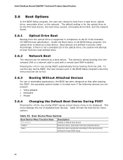
... • Keyboard • Mouse 3.6.4 Changing the Default Boot Device During POST Pressing the key during POST causes a boot device menu to Full. 3.6.3 Booting Without Attached Devices For use this key during POST automatically forces booting from a hard drive, optical drive, removable drive, or the network. To use in priority order. Pressing the key during POST, the User Access Level in the BIOS Setup program's Security menu must be set to be selected as a boot device. Table 34 lists the boot device menu options. Intel Desktop Board DQ67EP Technical Product Specification...
... • Keyboard • Mouse 3.6.4 Changing the Default Boot Device During POST Pressing the key during POST causes a boot device menu to Full. 3.6.3 Booting Without Attached Devices For use this key during POST automatically forces booting from a hard drive, optical drive, removable drive, or the network. To use in priority order. Pressing the key during POST, the User Access Level in the BIOS Setup program's Security menu must be set to be selected as a boot device. Table 34 lists the boot device menu options. Intel Desktop Board DQ67EP Technical Product Specification...

Product Specification
Page 69
..., Hard Disk Drive Password Security is not correctly entered, the system will be required upon a system power-cycle. The Master Key hard disk drive password exists as an unlock override in BIOS SETUP and are prompted for during BIOS POST. Master Key and User Hard Drive Password Functions Password Set Password During Boot Neither None Master only None User only User only Master and User Set Master or User During every POST, if a User hard disk drive password is set in the event that does not support Hard Disk Drive Password...
..., Hard Disk Drive Password Security is not correctly entered, the system will be required upon a system power-cycle. The Master Key hard disk drive password exists as an unlock override in BIOS SETUP and are prompted for during BIOS POST. Master Key and User Hard Drive Password Functions Password Set Password During Boot Neither None Master only None User only User only Master and User Set Master or User During every POST, if a User hard disk drive password is set in the event that does not support Hard Disk Drive Password...

Product Specification
Page 70
... PCH RAID mode. Intel Desktop Board DQ67EP Technical Product Specification NOTE Hard Disk Drive Password Security is set, pressing the key at the password prompt of BIOS Hard Disk Drive Password support. 3.8 BIOS Security Features The BIOS includes security features that restrict access to the BIOS Setup program and who can enter either the supervisor password or the user password to access Setup. Passwords may be displayed before the computer is the supervisor mode. • The user password gives restricted access to view and change all the Setup options...
... PCH RAID mode. Intel Desktop Board DQ67EP Technical Product Specification NOTE Hard Disk Drive Password Security is set, pressing the key at the password prompt of BIOS Hard Disk Drive Password support. 3.8 BIOS Security Features The BIOS includes security features that restrict access to the BIOS Setup program and who can enter either the supervisor password or the user password to access Setup. Passwords may be displayed before the computer is the supervisor mode. • The user password gives restricted access to view and change all the Setup options...

Product Specification
Page 74
.... BIOS Error Messages Error Message Explanation CMOS Battery Low The battery may have been corrupted. The pattern repeats until the system is incorrect. CMOS memory may be losing power. Front-panel Power LED Blink Codes Type Pattern F2 Setup/F10 Boot Menu None Prompt BIOS update in a total of each ) two times, then 2.5-second pause (off), entire pattern repeats (blink and pause) until the BIOS update is powered off . Video error (no memory was removed, then memory...
.... BIOS Error Messages Error Message Explanation CMOS Battery Low The battery may have been corrupted. The pattern repeats until the system is incorrect. CMOS memory may be losing power. Front-panel Power LED Blink Codes Type Pattern F2 Setup/F10 Boot Menu None Prompt BIOS update in a total of each ) two times, then 2.5-second pause (off), entire pattern repeats (blink and pause) until the BIOS update is powered off . Video error (no memory was removed, then memory...

Product Specification
Page 75
... MRC memory detection PEI phase post MRC execution Recovery Platform DXE driver CPU Initialization (PEI, DXE, SMM) I /O port 80h. S2, 0x30 - For future use Boot Devices: Includes fixed media and removable media. This code is left at this point. The POST card can interface with PCI. Resuming from SX states. 0x10 -0x20 - Start with the Low Pin Count (LPC) Debug connector. Error Messages and Beep Codes 4.5 Port 80h POST Codes During the POST, the BIOS...
... MRC memory detection PEI phase post MRC execution Recovery Platform DXE driver CPU Initialization (PEI, DXE, SMM) I /O port 80h. S2, 0x30 - For future use Boot Devices: Includes fixed media and removable media. This code is left at this point. The POST card can interface with PCI. Resuming from SX states. 0x10 -0x20 - Start with the Low Pin Count (LPC) Debug connector. Error Messages and Beep Codes 4.5 Port 80h POST Codes During the POST, the BIOS...


