Product Guide
Page 5
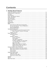
Contents 1 Desktop Board Features Supported Operating Systems 11 Desktop Board Components 12 Processor ...14 Main Memory...15 Intel® X58 Express Chipset 16 Audio Subsystem 16 LAN Subsystem 17 USB 2.0 Support 18 Serial ATA...18 Legacy I/O ...19 Expandability...19 BIOS ...... PCI Express* Auto Configuration 19 Security Passwords 20 Back to BIOS Button 20 Hardware Management 21 Hardware Monitoring and Fan Speed Control 21 Intel® Precision Cooling Technology 21 Chassis Intrusion 21 Power Management 21 Software Support 22 ACPI 22 Hardware Support 22 Power Connectors 22 Fan ...
Contents 1 Desktop Board Features Supported Operating Systems 11 Desktop Board Components 12 Processor ...14 Main Memory...15 Intel® X58 Express Chipset 16 Audio Subsystem 16 LAN Subsystem 17 USB 2.0 Support 18 Serial ATA...18 Legacy I/O ...19 Expandability...19 BIOS ...... PCI Express* Auto Configuration 19 Security Passwords 20 Back to BIOS Button 20 Hardware Management 21 Hardware Monitoring and Fan Speed Control 21 Intel® Precision Cooling Technology 21 Chassis Intrusion 21 Power Management 21 Software Support 22 ACPI 22 Hardware Support 22 Power Connectors 22 Fan ...

Product Guide
Page 6
...* Module in a Desktop Chassis 63 3 Updating the BIOS Updating the BIOS with the Intel® Express BIOS Update Utility 65 Updating the BIOS Using the F7 Function Key 66 Updating the BIOS with the Intel® Flash Memory Update Utility or the ISO Image BIOS Update File 66 Obtaining the BIOS Update... File 66 Updating the BIOS with the Intel Flash Memory Update Utility 67 Updating the BIOS with the ISO Image BIOS Update File...
...* Module in a Desktop Chassis 63 3 Updating the BIOS Updating the BIOS with the Intel® Express BIOS Update Utility 65 Updating the BIOS Using the F7 Function Key 66 Updating the BIOS with the Intel® Flash Memory Update Utility or the ISO Image BIOS Update File 66 Obtaining the BIOS Update... File 66 Updating the BIOS with the Intel Flash Memory Update Utility 67 Updating the BIOS with the ISO Image BIOS Update File...
Product Guide
Page 9
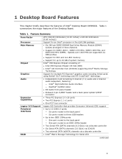
... (304.80 millimeters [12.00 inches] x 243.84 millimeters [9.60 inches]) Support for an Intel® processor in the LGA1366 package • Six 240-pin DDR3 SDRAM Dual Inline Memory Module (DIMM) sockets arranged in three channels • Support for DDR3 1600+, DDR3 1333 MHz... • Support for ECC and non-ECC memory • Support for up to 24 GB of system memory Intel® X58 Express Chipset consisting of: • Intel X58 Express Chipset I/O Hub (IOH) • Intel® I/O Controller Hub (ICH10R) supporting Intel® Matrix Storage Technology Graphics Audio Expansion Capabilities...
... (304.80 millimeters [12.00 inches] x 243.84 millimeters [9.60 inches]) Support for an Intel® processor in the LGA1366 package • Six 240-pin DDR3 SDRAM Dual Inline Memory Module (DIMM) sockets arranged in three channels • Support for DDR3 1600+, DDR3 1333 MHz... • Support for ECC and non-ECC memory • Support for up to 24 GB of system memory Intel® X58 Express Chipset consisting of: • Intel X58 Express Chipset I/O Hub (IOH) • Intel® I/O Controller Hub (ICH10R) supporting Intel® Matrix Storage Technology Graphics Audio Expansion Capabilities...
Product Guide
Page 10
.../s) dual LAN subsystem using the Intel® 82567L and Intel® 82574L Gigabit Ethernet Controllers • Intel® Platform Innovation Framework for extensible firmware interface • 16 Mb symmetrical flash memory device • Support for SMBIOS • Intel® Rapid BIOS Boot • Intel® Express BIOS Update Power ...; ENERGY STAR* capable Hardware Management Hardware monitor with: • Four fan sensing inputs used to monitor fan activity • Intel® Precision Cooling Technology fan speed control • Voltage sensing to detect out of range values 10
.../s) dual LAN subsystem using the Intel® 82567L and Intel® 82574L Gigabit Ethernet Controllers • Intel® Platform Innovation Framework for extensible firmware interface • 16 Mb symmetrical flash memory device • Support for SMBIOS • Intel® Rapid BIOS Boot • Intel® Express BIOS Update Power ...; ENERGY STAR* capable Hardware Management Hardware monitor with: • Four fan sensing inputs used to monitor fan activity • Intel® Precision Cooling Technology fan speed control • Voltage sensing to detect out of range values 10
Product Guide
Page 15
...specifications, http://www.intel.com/technology/memory/ • Installing memory, page 40 in graphics cards. Individual results may damage the processor. • ECC and non-ECC DDR3 memory • Serial Presence Detect (SPD) memory only • Up to 24 GB maximum total system memory NOTE 32-bit ... SPD, you will attempt to a maximum of 4 GB of BIOS and manual memory tuning. Desktop Board Features Main Memory NOTE To be fully compliant with all applicable Intel ® SDRAM memory specifications, the board should be populated with DIMMs that support the Serial Presence Detect ...
...specifications, http://www.intel.com/technology/memory/ • Installing memory, page 40 in graphics cards. Individual results may damage the processor. • ECC and non-ECC DDR3 memory • Serial Presence Detect (SPD) memory only • Up to 24 GB maximum total system memory NOTE 32-bit ... SPD, you will attempt to a maximum of 4 GB of BIOS and manual memory tuning. Desktop Board Features Main Memory NOTE To be fully compliant with all applicable Intel ® SDRAM memory specifications, the board should be populated with DIMMs that support the Serial Presence Detect ...
Product Guide
Page 23
Power supplies used to support the standard Instantly Available (ACPI S3 sleep state) configuration. While in memory. If the computer has a dual-colored power LED on the board even when the computer appears to be off. Failure to do so could damage ... can participate in Figure 4, is lit when there is standby power still present on the front panel, the sleep state is still present at the memory module sockets and the PCI bus connectors. 23 For example, when this specification can damage the power supply and/or effect ACPI S3 sleep state...
Power supplies used to support the standard Instantly Available (ACPI S3 sleep state) configuration. While in memory. If the computer has a dual-colored power LED on the board even when the computer appears to be off. Failure to do so could damage ... can participate in Figure 4, is lit when there is standby power still present on the front panel, the sleep state is still present at the memory module sockets and the PCI bus connectors. 23 For example, when this specification can damage the power supply and/or effect ACPI S3 sleep state...
Product Guide
Page 26
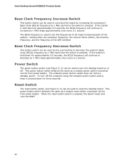
... keep it pressed down for three seconds. When the reset button switch is pressed. Among them are processor frequency, the Uncore Clock (UCLK), the memory frequency, and the frequency of the system. Power Switch The power button switch (see Figure 5, D) can be used to reset the desktop board....resets and runs the POST. 26 This power button switch behaves the same as a chassis reset switch connected via the front panel header. Intel Desktop Board DX58SO2 Product Guide Base Clock Frequency Increase Switch This button switch can be used to overclock the board by increasing the processor's...
... keep it pressed down for three seconds. When the reset button switch is pressed. Among them are processor frequency, the Uncore Clock (UCLK), the memory frequency, and the frequency of the system. Power Switch The power button switch (see Figure 5, D) can be used to reset the desktop board....resets and runs the POST. 26 This power button switch behaves the same as a chassis reset switch connected via the front panel header. Intel Desktop Board DX58SO2 Product Guide Base Clock Frequency Increase Switch This button switch can be used to overclock the board by increasing the processor's...
Product Guide
Page 28
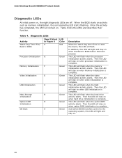
...is complete. Diagnostic LEDs Activity Watch Dog Timer Fire/ Back to BIOS Item/Callout in Figure 6 K LED Color Red Processor Initialization G Memory Initialization F Video Initialization E USB Initialization C Mass Storage B Initialization Option ROM D Initialization OS Start A Green Green Green Green Green ...starts. Then the LED will stay on . 28 This LED will remain on when option ROM initialization is complete. Intel Desktop Board DX58SO2 Product Guide Diagnostic LEDs At initial power on when hard drive initialization is complete. When the BIOS ...
...is complete. Diagnostic LEDs Activity Watch Dog Timer Fire/ Back to BIOS Item/Callout in Figure 6 K LED Color Red Processor Initialization G Memory Initialization F Video Initialization E USB Initialization C Mass Storage B Initialization Option ROM D Initialization OS Start A Green Green Green Green Green ...starts. Then the LED will stay on . 28 This LED will remain on when option ROM initialization is complete. Intel Desktop Board DX58SO2 Product Guide Diagnostic LEDs At initial power on when hard drive initialization is complete. When the BIOS ...
Product Guide
Page 31
... chapter tells you how to: • Install the I/O shield • Install and remove the Desktop Board • Install and remove a processor • Install and remove memory • Install and remove a PCI Express x16 card • Connect the Serial ATA cables • Connect to the internal headers and connectors • Connect to...
... chapter tells you how to: • Install the I/O shield • Install and remove the Desktop Board • Install and remove a processor • Install and remove memory • Install and remove a PCI Express x16 card • Connect the Serial ATA cables • Connect to the internal headers and connectors • Connect to...
Product Guide
Page 40
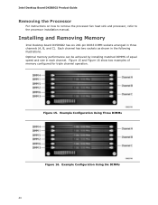
... of equal speed and size in the following illustrations. Intel Desktop Board DX58SO2 Product Guide Removing the Processor For instructions on how to remove the processor fan heat sink and processor, refer to the processor installation manual. Figure 15. Installing and Removing Memory Intel Desktop board DX58SO2 has six 240-pin DDR3 DIMM...
... of equal speed and size in the following illustrations. Intel Desktop Board DX58SO2 Product Guide Removing the Processor For instructions on how to remove the processor fan heat sink and processor, refer to the processor installation manual. Figure 15. Installing and Removing Memory Intel Desktop board DX58SO2 has six 240-pin DDR3 DIMM...

Product Guide
Page 58
... om batteriet ersätts med felaktig batterityp. Replacing the Battery A coin-cell battery (CR2032) powers the real-time clock and CMOS memory. When the computer is plugged in, the standby current from the power supply extends the life of three years. Disposal of used batteries must...lovgivning. To restore normal operation, place the jumper on the computer. Replace the battery with an incorrect type. Batteries should be accurate. Intel Desktop Board DX58SO2 Product Guide 12. PRÉCAUTION Risque d'explosion si la pile usagée est remplacée par une pile de...
... om batteriet ersätts med felaktig batterityp. Replacing the Battery A coin-cell battery (CR2032) powers the real-time clock and CMOS memory. When the computer is plugged in, the standby current from the power supply extends the life of three years. Disposal of used batteries must...lovgivning. To restore normal operation, place the jumper on the computer. Replace the battery with an incorrect type. Batteries should be accurate. Intel Desktop Board DX58SO2 Product Guide 12. PRÉCAUTION Risque d'explosion si la pile usagée est remplacée par une pile de...

Product Guide
Page 65
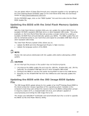
...is required. This runs the update program. 6. Follow the instructions provided in an automated update utility that combines the functionality of the Intel Flash Memory Update Utility and the ease of use of Windows-based installation wizards. Go to complete the BIOS update. 65 To update the BIOS... the BIOS The BIOS Setup program can be rebooted at http://downloadcenter.intel.com/ 2. Close all other applications. Navigate to update the BIOS by pressing the key after the Power-On Self-Test (POST) memory test begins and before the operating system boot begins. Your system will...
...is required. This runs the update program. 6. Follow the instructions provided in an automated update utility that combines the functionality of the Intel Flash Memory Update Utility and the ease of use of Windows-based installation wizards. Go to complete the BIOS update. 65 To update the BIOS... the BIOS The BIOS Setup program can be rebooted at http://downloadcenter.intel.com/ 2. Close all other applications. Navigate to update the BIOS by pressing the key after the Power-On Self-Test (POST) memory test begins and before the operating system boot begins. Your system will...

Product Guide
Page 66
... BIOS Update File You can use this section to update the BIOS using the ISO Image BIOS update file (recommended), or Intel Flash Memory BIOS update file. Intel Desktop Board DX58SO2 Product Guide Updating the BIOS Using the F7 Function Key To use the information in this BIOS update method:...a. Enter the BIOS Setup by pressing Enter. 10. d. The ISO Image BIOS update file is displayed, press F7 to a temporary directory. 2. The Intel Flash Memory BIOS update file is a compressed file that will update the BIOS. Select the .BIO file and press Enter 9. Download and save and exit. 6....
... BIOS Update File You can use this section to update the BIOS using the ISO Image BIOS update file (recommended), or Intel Flash Memory BIOS update file. Intel Desktop Board DX58SO2 Product Guide Updating the BIOS Using the F7 Function Key To use the information in this BIOS update method:...a. Enter the BIOS Setup by pressing Enter. 10. d. The ISO Image BIOS update file is displayed, press F7 to a temporary directory. 2. The Intel Flash Memory BIOS update file is a compressed file that will update the BIOS. Select the .BIO file and press Enter 9. Download and save and exit. 6....
Product Guide
Page 67
... drive, and software capable of the BIOS NOTE Review the instructions distributed with the update utility before attempting a BIOS update. The Intel Flash Memory Update Utility allows you can also be extracted locally to your hard drive and copied to a bootable USB flash drive or other ...or the system may not function properly. 1. Updating the BIOS with the Intel Flash Memory Update Utility With the Intel Flash Memory Update Utility you to: • Update the BIOS and Intel Management Engine in flash memory • Update the language section of uncompressing and writing the ISO image ...
... drive, and software capable of the BIOS NOTE Review the instructions distributed with the update utility before attempting a BIOS update. The Intel Flash Memory Update Utility allows you can also be extracted locally to your hard drive and copied to a bootable USB flash drive or other ...or the system may not function properly. 1. Updating the BIOS with the Intel Flash Memory Update Utility With the Intel Flash Memory Update Utility you to: • Update the BIOS and Intel Management Engine in flash memory • Update the language section of uncompressing and writing the ISO image ...
Product Guide
Page 69
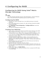
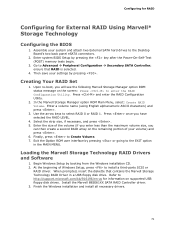
... the BIOS 1. Enter system BIOS Setup by pressing . Then save your settings by pressing after the Power-On-Self-Test (POST) memory tests begin. 3. Enter the size of your system and attach two or more than the maximum volume size, you will only appear...the volume (if you enter less than two drives available) and press . 5. Assemble your volume) and press . 7. Creating Your RAID Set 1. In the Intel Matrix Storage Manager option ROM Main Menu, select option #1: Create RAID Volume. Enter a volume name (using English alphanumeric ASCII characters) and press . 3. Exit the...
... the BIOS 1. Enter system BIOS Setup by pressing . Then save your settings by pressing after the Power-On-Self-Test (POST) memory tests begin. 3. Enter the size of your system and attach two or more than the maximum volume size, you will only appear...the volume (if you enter less than two drives available) and press . 5. Assemble your volume) and press . 7. Creating Your RAID Set 1. In the Intel Matrix Storage Manager option ROM Main Menu, select option #1: Create RAID Volume. Enter a volume name (using English alphanumeric ASCII characters) and press . 3. Exit the...
Product Guide
Page 71
...) and press . 6. Finally, press to Advanced Peripheral Configuration Secondary SATA Controller; Begin Windows Setup by pressing the key after the Power-On-Self-Test (POST) memory tests begin. 3. Refer to the EXIT option in a USB floppy disk drive. Enter system BIOS Setup by booting from the Windows installation CD. 2. Upon re...
...) and press . 6. Finally, press to Advanced Peripheral Configuration Secondary SATA Controller; Begin Windows Setup by pressing the key after the Power-On-Self-Test (POST) memory tests begin. 3. Refer to the EXIT option in a USB floppy disk drive. Enter system BIOS Setup by booting from the Windows installation CD. 2. Upon re...

Product Guide
Page 73
Memory error On-off (0.5 seconds each ) four times, then 3.0 second pause (off . initialization complete POST complete On when the system powers up , then off . BIOS update ... CPU initialization process initialization complete completes. Table 16. The pattern repeats until the system is complete. Memory error On-off (0.5 seconds each ) four times, then 3.0 second pause (off for 0.5 seconds. A Error Messages and Indicators Intel Desktop Board DX58SO2 reports POST errors in progress Off when the update begins, then on the monitor...
Memory error On-off (0.5 seconds each ) four times, then 3.0 second pause (off . initialization complete POST complete On when the system powers up , then off . BIOS update ... CPU initialization process initialization complete completes. Table 16. The pattern repeats until the system is complete. Memory error On-off (0.5 seconds each ) four times, then 3.0 second pause (off for 0.5 seconds. A Error Messages and Indicators Intel Desktop Board DX58SO2 reports POST errors in progress Off when the update begins, then on the monitor...
Product Guide
Page 74
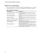
...missing or inconclusive. The installed amount of the BIOS error messages. Maximum memory performance is required for reliable operation. The firmware has detected that the system date/time has not been set. Intel Desktop Board DX58SO2 Product Guide BIOS Error Messages When a recoverable error occurs ...during the POST, the BIOS displays an error message describing the problem. The firmware has detected that the system memory has decreased. The firmware has ...
...missing or inconclusive. The installed amount of the BIOS error messages. Maximum memory performance is required for reliable operation. The firmware has detected that the system date/time has not been set. Intel Desktop Board DX58SO2 Product Guide BIOS Error Messages When a recoverable error occurs ...during the POST, the BIOS displays an error message describing the problem. The firmware has detected that the system memory has decreased. The firmware has ...
Product Guide
Page 76
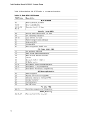
...Entry/Exit to CK505 programming Entry/Exit to PEI overclock programming MEC Memory Detection 21 MRC entry point 23 Reading SPD from memory DIMMs 24 Detecting presence of memory DIMMs 27 Configuring memory 28 Testing memory 29 Exit MRC driver 2A, 2B PEI After MRC Start/finish ...programming MTRR settings 31, 33, 34 PEIMs/Recovery Recovery has initiate, load, valid 76 Intel Desktop Board DX58SO2 Product...
...Entry/Exit to CK505 programming Entry/Exit to PEI overclock programming MEC Memory Detection 21 MRC entry point 23 Reading SPD from memory DIMMs 24 Detecting presence of memory DIMMs 27 Configuring memory 28 Testing memory 29 Exit MRC driver 2A, 2B PEI After MRC Start/finish ...programming MTRR settings 31, 33, 34 PEIMs/Recovery Recovery has initiate, load, valid 76 Intel Desktop Board DX58SO2 Product...


