User Manual
Page 11
... observable in via a x1 PCI Express* port. VCC (CPU core) is terminated to the traces on a substrate, such as the motherboard. The system bus is the core power for the processor. The name of the development board that uses Intel® Core™ 2 Duo processor with the Mobile Intel GM45 Express Chipset and DDR2 SDRAM The contact point...
... observable in via a x1 PCI Express* port. VCC (CPU core) is terminated to the traces on a substrate, such as the motherboard. The system bus is the core power for the processor. The name of the development board that uses Intel® Core™ 2 Duo processor with the Mobile Intel GM45 Express Chipset and DDR2 SDRAM The contact point...
User Manual
Page 19
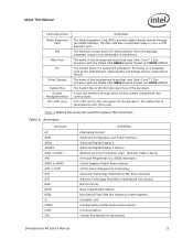
... for drivers and software for adapters not provided with this development kit. Other Devices and Adapters: The development board functions much like a standard desktop computer motherboard. Operating System: The user must supply any needed operating system installation files and licenses. Please contact the respective vendors for drivers and necessary software for...
... for drivers and software for adapters not provided with this development kit. Other Devices and Adapters: The development board functions much like a standard desktop computer motherboard. Operating System: The user must supply any needed operating system installation files and licenses. Please contact the respective vendors for drivers and necessary software for...

User Manual
Page 23
...BIOS The default BIOS settings may need to be modified to enable or disable various features of the AMI* BIOS is pre-loaded on the motherboard at the ATX power supply. The BIOS settings are three options for 4 seconds. Press the power button on the development board. Note: ...possible to asynchronously shut the system down by shutting off power at SW1C1 to begin power-down. 3. Other BIOS vendors also support the Intel Core 2 Duo with Intel GS45 Express Chipset. Press the F2 key or Delete key during the Power On Self Test (POST). Development Kit User's Manual 23 Power...
...BIOS The default BIOS settings may need to be modified to enable or disable various features of the AMI* BIOS is pre-loaded on the motherboard at the ATX power supply. The BIOS settings are three options for 4 seconds. Press the power button on the development board. Note: ...possible to asynchronously shut the system down by shutting off power at SW1C1 to begin power-down. 3. Other BIOS vendors also support the Intel Core 2 Duo with Intel GS45 Express Chipset. Press the F2 key or Delete key during the Power On Self Test (POST). Development Kit User's Manual 23 Power...

User Manual
Page 27
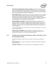
... PCI Extension card Comments SL9400 has 1066 MT/s FSB; 1.86 GHz core; 6 MB L2 cache; 17 W TDP; 2 Cores; 956-ball µFCBGA package. Development Board Features Table 6....Intel® Core™ 2 Duo processor SL9400 or Intel® Core™ 2 Duo processor SU9400 Intel® GS45 Express Graphics and Memory Controller Hub (GS45 GMCH) ICH9M-Enhanced SFF 512 MB DDR3 memory down with 512-MB DDR3 1067 MT/s (x16 devices, four device on top and four device on motherboard...support Intel GS45 Express Chipset supports quad monitors, but only has two video pipes which support two different...
... PCI Extension card Comments SL9400 has 1066 MT/s FSB; 1.86 GHz core; 6 MB L2 cache; 17 W TDP; 2 Cores; 956-ball µFCBGA package. Development Board Features Table 6....Intel® Core™ 2 Duo processor SL9400 or Intel® Core™ 2 Duo processor SU9400 Intel® GS45 Express Graphics and Memory Controller Hub (GS45 GMCH) ICH9M-Enhanced SFF 512 MB DDR3 memory down with 512-MB DDR3 1067 MT/s (x16 devices, four device on top and four device on motherboard...support Intel GS45 Express Chipset supports quad monitors, but only has two video pipes which support two different...
User Manual
Page 28
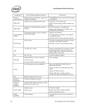
...multi-package (SOIC-8 & SOIC-16) device No FWH connector on motherboard Support only through Port-80 add-in card (through the TPM header) Support via interposer Use Mott Canyon-4 daughter card (support via sideband cable) Intel HD Audio routed to eSATA+USB combo connector with resistor stuffing option for...SRC clocks Twelve 33-MHz PCI clocks 48-MHz USB clock, 14-MHz ref clock, 96-MHz Dot clock, Spread spectrum clocks Intel® Mobile Voltage Positioning Intel® MVP-6 for processor core Desktop mode Mobile mode Port-80 display ATX power supply Battery pack (smart battery support) Mobile...
...multi-package (SOIC-8 & SOIC-16) device No FWH connector on motherboard Support only through Port-80 add-in card (through the TPM header) Support via interposer Use Mott Canyon-4 daughter card (support via sideband cable) Intel HD Audio routed to eSATA+USB combo connector with resistor stuffing option for...SRC clocks Twelve 33-MHz PCI clocks 48-MHz USB clock, 14-MHz ref clock, 96-MHz Dot clock, Spread spectrum clocks Intel® Mobile Voltage Positioning Intel® MVP-6 for processor core Desktop mode Mobile mode Port-80 display ATX power supply Battery pack (smart battery support) Mobile...
User Manual
Page 35
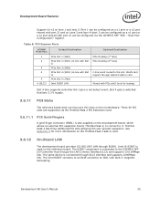
...) PCIe Slot 2 (J6D1) (in-line with Slot 1) PCIe Slot 3 (J8B3) PCIe Slot 4 (J8D1) (in card Muxed with Slot 3) PCIe Slot 5 (J7B1) Intel 82567 LAN Optional Destination PCIe Docking (1st lane) PCIe Docking (2nd lane) C-link south routed to this slot. WLAN card support through the LAN Connect... net detect event, Slot 4 gets a switched Auxiliary 3.3 V supply. 3.6.11 PCI Slots The reference board does not have any PCI slots on the motherboard. The 82567 component is connected through EU8A1. The same device is connected to an RJ45 connector at J5A1 with built in card. 3.6.12 On-Board...
...) PCIe Slot 2 (J6D1) (in-line with Slot 1) PCIe Slot 3 (J8B3) PCIe Slot 4 (J8D1) (in card Muxed with Slot 3) PCIe Slot 5 (J7B1) Intel 82567 LAN Optional Destination PCIe Docking (1st lane) PCIe Docking (2nd lane) C-link south routed to this slot. WLAN card support through the LAN Connect... net detect event, Slot 4 gets a switched Auxiliary 3.3 V supply. 3.6.11 PCI Slots The reference board does not have any PCI slots on the motherboard. The 82567 component is connected through EU8A1. The same device is connected to an RJ45 connector at J5A1 with built in card. 3.6.12 On-Board...

User Manual
Page 37
... J9C2. The board has a power connector J5J1 to Section 4.3.1, Table 17. A green LED at the back panel. Due to enable hot plug/removal on the Motherboard without using the docking card. A jumper J7H1 is also routed to the device on the ATA channel. Six USB ports are for them on the... motherboard 3.6.16 USB Connectors ICH9M-E SFF provides a total of this only one USB port is that Port 9 can be externally powered. The remaining one of these ...
... J9C2. The board has a power connector J5J1 to Section 4.3.1, Table 17. A green LED at the back panel. Due to enable hot plug/removal on the Motherboard without using the docking card. A jumper J7H1 is also routed to the device on the ATA channel. Six USB ports are for them on the... motherboard 3.6.16 USB Connectors ICH9M-E SFF provides a total of this only one USB port is that Port 9 can be externally powered. The remaining one of these ...
User Manual
Page 47
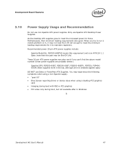
... supplies work in Windows. § Development Kit User's Manual 47 You may not load the 5.0V rail enough to meet the increased power for those Motherboards, their minimum loading requirements also grew. FSP300-60BTVS meets this requirement and is an ATX12V 1.1 Spec (note that this part may be End Of Life...
... supplies work in Windows. § Development Kit User's Manual 47 You may not load the 5.0V rail enough to meet the increased power for those Motherboards, their minimum loading requirements also grew. FSP300-60BTVS meets this requirement and is an ATX12V 1.1 Spec (note that this part may be End Of Life...
User Manual
Page 55
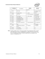
When no jumper cap is to be shorted are indicated as 1-2 (to short pin 1 to pin 2), or 2-3 (to short pin 2 to be placed on the motherboard. When a jumper cap is placed over two pins, it is designated as 1-X. When there are more pins mounted on the jumper, it is designated as 1-2. ...
When no jumper cap is to be shorted are indicated as 1-2 (to short pin 1 to pin 2), or 2-3 (to short pin 2 to be placed on the motherboard. When a jumper cap is placed over two pins, it is designated as 1-X. When there are more pins mounted on the jumper, it is designated as 1-2. ...
User Manual
Page 62
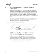
... (Thimble Peak 2) is provided to offer 3 PCI slots and one goldfinger PCI slot on the evaluation board schematics. CLKRUN protocol is supported on the respective motherboards. The system BIOS then performs all needed initialization to Display Port/HDMI connectors. PCI Expansion Card (Thimble Peak 2) A.3 HDMI and Display Port Video Interface Add...
... (Thimble Peak 2) is provided to offer 3 PCI slots and one goldfinger PCI slot on the evaluation board schematics. CLKRUN protocol is supported on the respective motherboards. The system BIOS then performs all needed initialization to Display Port/HDMI connectors. PCI Expansion Card (Thimble Peak 2) A.3 HDMI and Display Port Video Interface Add...
User Manual
Page 83
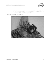
Step 9 - CPU Thermal Solution (Heatsink) Installation 9. Plugging in the Fan Development Kit User's Manual 83 Figure 29. Plug the fan connector for the heatsink onto the CPU fan header (J2B3) on the motherboard. (See the figure below) The CPU fan header (J2B3) is a 3-pin connector with the words CPU Fan printed beside it.
Step 9 - CPU Thermal Solution (Heatsink) Installation 9. Plugging in the Fan Development Kit User's Manual 83 Figure 29. Plug the fan connector for the heatsink onto the CPU fan header (J2B3) on the motherboard. (See the figure below) The CPU fan header (J2B3) is a 3-pin connector with the words CPU Fan printed beside it.

