User Manual
Page 2
... processor families. Contact your local Intel sales office or your distributor to them. Copies of Intel Corporation or its subsidiaries in the United States and other countries. *Other names and brands may have no responsibility whatsoever for conflicts or incompatibilities arising from published specifications. Leap ahead., Intel. logo, Intel NetBurst, Intel NetMerge, Intel NetStructure, Intel SingleDriver, Intel SpeedStep, Intel StrataFlash, Intel Viiv, Intel...
... processor families. Contact your local Intel sales office or your distributor to them. Copies of Intel Corporation or its subsidiaries in the United States and other countries. *Other names and brands may have no responsibility whatsoever for conflicts or incompatibilities arising from published specifications. Leap ahead., Intel. logo, Intel NetBurst, Intel NetMerge, Intel NetStructure, Intel SingleDriver, Intel SpeedStep, Intel StrataFlash, Intel Viiv, Intel...

User Manual
Page 10
...SMI#, SLP#, and STPCLK# utilize GTL+ input buffers. The Intel Mobile Voltage Positioning specification for the processor to a single processor. 10 Development Kit User's Manual AGTL+ output buffers differ from GTL+ buffers with the Mobile Intel GS45 Express Chipset (Small Form Factor) and DDR3 SDRAM The ... also utilize GTL+ output buffers. However, all of Terms and Acronyms Table 2 defines terms used in order for the Intel® Core™ 2 Duo Processor. The development board has such a port and it is represented by the signal name followed by the port abbreviation, a...
...SMI#, SLP#, and STPCLK# utilize GTL+ input buffers. The Intel Mobile Voltage Positioning specification for the processor to a single processor. 10 Development Kit User's Manual AGTL+ output buffers differ from GTL+ buffers with the Mobile Intel GS45 Express Chipset (Small Form Factor) and DDR3 SDRAM The ... also utilize GTL+ output buffers. However, all of Terms and Acronyms Table 2 defines terms used in order for the Intel® Core™ 2 Duo Processor. The development board has such a port and it is represented by the signal name followed by the port abbreviation, a...
User Manual
Page 17
... development board in the development kit. Note: The Intel® Core™ 2 Duo SU9400 processor at 1.2 GHz core frequency is on the Intel embedded roadmap offering and has embedded market 7 year ...availability. 2.2 Development Kit Contents The following hardware, software and documentation are included in this development board is not on this kit may have embedded market 7 year availability. Getting Started 2 Getting Started This chapter identifies the development kit's key components, features and specifications...
... development board in the development kit. Note: The Intel® Core™ 2 Duo SU9400 processor at 1.2 GHz core frequency is on the Intel embedded roadmap offering and has embedded market 7 year ...availability. 2.2 Development Kit Contents The following hardware, software and documentation are included in this development board is not on this kit may have embedded market 7 year availability. Getting Started 2 Getting Started This chapter identifies the development kit's key components, features and specifications...

User Manual
Page 38
... development board and is provided through strapping option) Docking Connector (default) Connector J3A1 (4 stacked USB Connector) J6H4 J6H2 J3A1 (RJ45 with an Intel 82802 Firmware Hub Device assembled can disable the SIO by holding it in reset. A Port 80 card with Dual USB Connector) J6J1 J9C2 3.6....17 LPC Super I /O Header (port 9 is routed to the 2-3 positions can be tested in the "LPC Slot and Sideband Header Specification". 3.6.18 Serial, IrDA The SMSC SIO chip incorporates a serial port, and IrDA (Infrared), as well as the SIO on sheet 49 of the schematics...
... development board and is provided through strapping option) Docking Connector (default) Connector J3A1 (4 stacked USB Connector) J6H4 J6H2 J3A1 (RJ45 with an Intel 82802 Firmware Hub Device assembled can disable the SIO by holding it in reset. A Port 80 card with Dual USB Connector) J6J1 J9C2 3.6....17 LPC Super I /O Header (port 9 is routed to the 2-3 positions can be tested in the "LPC Slot and Sideband Header Specification". 3.6.18 Serial, IrDA The SMSC SIO chip incorporates a serial port, and IrDA (Infrared), as well as the SIO on sheet 49 of the schematics...
User Manual
Page 40
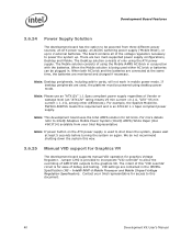
... User's Manual When the Mobile solution is being used either AC brick or batteries can be plugged in the IMVP6+ Specification (RS - Contact your Intel Representative Note: If power button on again. an ATX power supply, an AC/DC switching power supply ('Mobile Brick...an "ATX12V" rating means V5 min current =0.1 A, "ATX" V5 min current = 1.0 A, among other differences). Intel® IMVP-6 Mobile Processor and Mobile Chipset Voltage Regulation Specification). For example, the Sparkle Model No. When both AC brick and the batteries are two main supported power supply ...
... User's Manual When the Mobile solution is being used either AC brick or batteries can be plugged in the IMVP6+ Specification (RS - Contact your Intel Representative Note: If power button on again. an ATX power supply, an AC/DC switching power supply ('Mobile Brick...an "ATX12V" rating means V5 min current =0.1 A, "ATX" V5 min current = 1.0 A, among other differences). Intel® IMVP-6 Mobile Processor and Mobile Chipset Voltage Regulation Specification). For example, the Sparkle Model No. When both AC brick and the batteries are two main supported power supply ...
User Manual
Page 41
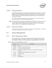
... and ITP-700. Development Board Features 3.6.26 Debug Interfaces An XDP (Extended Debug Port) connector is similar to the full-size ATX specification. Please contact an Intel representative for additional details. 3.6.27 Board Form-Factor The reference board form factor is provided at various power level, called the M-states....cable is used on the TPM header located at J9A1 Note: The XDP interface is necessary to get the older ITP tools to processor core is the highest power state, followed by software) Suspend To RAM (all switched rails are turned off . The board is compatible with ...
... and ITP-700. Development Board Features 3.6.26 Debug Interfaces An XDP (Extended Debug Port) connector is similar to the full-size ATX specification. Please contact an Intel representative for additional details. 3.6.27 Board Form-Factor The reference board form factor is provided at various power level, called the M-states....cable is used on the TPM header located at J9A1 Note: The XDP interface is necessary to get the older ITP tools to processor core is the highest power state, followed by software) Suspend To RAM (all switched rails are turned off . The board is compatible with ...

User Manual
Page 43
... Across Resistor: Calculated Power: EXAMPLE SYSTEM 0.002Ω 1.492 mV (746 mA) 1.113 mW Agilent 34401A (6 ½ digit display) Specification: (±0.0030% of reading) + (±0.0030% of range) Min Voltage Displayed: 1.49193 mV Calculated Power: 1.1129 mW Fluke 79 (3 digit display...) Specification: ±0.09% ±2 digits Min Voltage Displayed: Calculated Power: 1.47 mV 1.08 mW Max Voltage Displayed: Calculated Power: Error in Power:...
... Across Resistor: Calculated Power: EXAMPLE SYSTEM 0.002Ω 1.492 mV (746 mA) 1.113 mW Agilent 34401A (6 ½ digit display) Specification: (±0.0030% of reading) + (±0.0030% of range) Min Voltage Displayed: 1.49193 mV Calculated Power: 1.1129 mW Fluke 79 (3 digit display...) Specification: ±0.09% ±2 digits Min Voltage Displayed: Calculated Power: 1.47 mV 1.08 mW Max Voltage Displayed: Calculated Power: Error in Power:...

User Manual
Page 70
... that may be required for each. It supports the attachment of two independent PCI Express mini cards (Complied with Express mini card specification Rev1.0) with USB connection enabled for the PCI Express mini card WLAN product. Upham IV Interposer Card 70 Development Kit User's Manual The USB interface ...
... that may be required for each. It supports the attachment of two independent PCI Express mini cards (Complied with Express mini card specification Rev1.0) with USB connection enabled for the PCI Express mini card WLAN product. Upham IV Interposer Card 70 Development Kit User's Manual The USB interface ...