
User Manual
Page 5
...5 Fern Hill Development Board Components 49 Figure 3. Back Panel Connectors 51 Figure 4. Power On and Reset Buttons 57 Figure 9. Eaglemont Add-in the Fan 83 Figure 30. Upham IV Interposer Card 70 Figure 20. Backplate Pins 79 Figure 26. Step 8 - D-Connector to Component Video Cable 52 Figure ...before Rework 64 Figure 14. Applying the Thermal Grease 80 Figure 27. Installing the Heatsink 82 Figure 29. Step 9 - AUX Pull-Down Rework 66 Figure 17. Step 6 - Low Voltage HD Audio Rework (Sus Rail 76 Figure 25. Low Voltage HD Audio Rework (Always Rail 75 Figure ...
...5 Fern Hill Development Board Components 49 Figure 3. Back Panel Connectors 51 Figure 4. Power On and Reset Buttons 57 Figure 9. Eaglemont Add-in the Fan 83 Figure 30. Upham IV Interposer Card 70 Figure 20. Backplate Pins 79 Figure 26. Step 8 - D-Connector to Component Video Cable 52 Figure ...before Rework 64 Figure 14. Applying the Thermal Grease 80 Figure 27. Installing the Heatsink 82 Figure 29. Step 9 - AUX Pull-Down Rework 66 Figure 17. Step 6 - Low Voltage HD Audio Rework (Sus Rail 76 Figure 25. Low Voltage HD Audio Rework (Always Rail 75 Figure ...
User Manual
Page 21
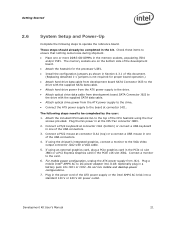
...AC power outlet. Development Kit User's Manual 21 These steps should already be completed by the user: 1. Plug the fan power in one of the ATX power supply or the Intel AMPS AC brick into J1G9. For mobile power configuration, unplug the ATX power supply from the ATX power supply to... the PCIE x16 slot J6B2. The memory sockets are on the bottom side of this document. (Replacing detached 1-x jumpers is not required for the processor U2E1. • Install the configuration jumpers as shown in the memory sockets, populating J5N1 and/or J5P1. Connect a monitor to operate the reference ...
...AC power outlet. Development Kit User's Manual 21 These steps should already be completed by the user: 1. Plug the fan power in one of the ATX power supply or the Intel AMPS AC brick into J1G9. For mobile power configuration, unplug the ATX power supply from the ATX power supply to... the PCIE x16 slot J6B2. The memory sockets are on the bottom side of this document. (Replacing detached 1-x jumpers is not required for the processor U2E1. • Install the configuration jumpers as shown in the memory sockets, populating J5N1 and/or J5P1. Connect a monitor to operate the reference ...
User Manual
Page 32
... processor supports a new processor state, Intel Deep Power Down Technology, that brings the CPU leakage power down to the CPU VCC Core VR. A jumper J2B2 is provided to incorporate "VID override" to allow the overriding of CPU VID outputs to the lowest possible. The core VR solution supports PSI2. Fan ... protocol is AGTL+ and will support up to support FAN Tacho output measurement for ease of 800 MT/s (200-MHz quad pumped, FSB-800) & 1067 MT/s (266-MHz quad pumped, FSB-1067). Processor Active Cooling The system supports PWM based FAN speed control. Front-Side Bus (FSB) The Front ...
... processor supports a new processor state, Intel Deep Power Down Technology, that brings the CPU leakage power down to the CPU VCC Core VR. A jumper J2B2 is provided to incorporate "VID override" to allow the overriding of CPU VID outputs to the lowest possible. The core VR solution supports PSI2. Fan ... protocol is AGTL+ and will support up to support FAN Tacho output measurement for ease of 800 MT/s (200-MHz quad pumped, FSB-800) & 1067 MT/s (266-MHz quad pumped, FSB-1067). Processor Active Cooling The system supports PWM based FAN speed control. Front-Side Bus (FSB) The Front ...

User Manual
Page 39
... supports one dual 1x8 PCI fan-out buffer (U7E4). 3.6.22 Real Time Clock An on the board, and the board shuts down. The SMC throttles the processor if it becomes hot. If the temperature of the fan is varied based on the temperature measurement. 3-pin fan headers J2B3 and J3C2 are ...provided to support FAN Tacho output measurement for the development board. The SMC/KBC controller supports...
... supports one dual 1x8 PCI fan-out buffer (U7E4). 3.6.22 Real Time Clock An on the board, and the board shuts down. The SMC throttles the processor if it becomes hot. If the temperature of the fan is varied based on the temperature measurement. 3-pin fan headers J2B3 and J3C2 are ...provided to support FAN Tacho output measurement for the development board. The SMC/KBC controller supports...

User Manual
Page 51
... other end) (not included in the kit). Figure 3. S-video is connected to the development board using a D-connector to devices inside the computer chassis, such as fans and internal peripherals. Most of the connectors provide operating voltage (+5V DC and +12V DC, for powering devices external to the computer, the interconnecting cable...
... other end) (not included in the kit). Figure 3. S-video is connected to the development board using a D-connector to devices inside the computer chassis, such as fans and internal peripherals. Most of the connectors provide operating voltage (+5V DC and +12V DC, for powering devices external to the computer, the interconnecting cable...

User Manual
Page 78
.... CPU Thermal Solution (Heatsink) Installation Appendix D CPU Thermal Solution (Heatsink) Installation It is necessary for the Intel® Core™ 2 Duo processor to have a thermal solution attached to it within its package and separate the fan heatsink portion from the heatsink backplate. 3. Examine the base of the CPU heatsink with isopropyl alcohol. 78 Development...
.... CPU Thermal Solution (Heatsink) Installation Appendix D CPU Thermal Solution (Heatsink) Installation It is necessary for the Intel® Core™ 2 Duo processor to have a thermal solution attached to it within its package and separate the fan heatsink portion from the heatsink backplate. 3. Examine the base of the CPU heatsink with isopropyl alcohol. 78 Development...
User Manual
Page 83
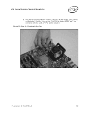
Plug the fan connector for the heatsink onto the CPU fan header (J2B3) on the motherboard. (See the figure below) The CPU fan header (J2B3) is a 3-pin connector with the words CPU Fan printed beside it. Step 9 - Plugging in the Fan Development Kit User's Manual 83 Figure 29. CPU Thermal Solution (Heatsink) Installation 9.
Plug the fan connector for the heatsink onto the CPU fan header (J2B3) on the motherboard. (See the figure below) The CPU fan header (J2B3) is a 3-pin connector with the words CPU Fan printed beside it. Step 9 - Plugging in the Fan Development Kit User's Manual 83 Figure 29. CPU Thermal Solution (Heatsink) Installation 9.