Product Guide
Page 4
... D845WN Product Guide Installing and Removing Memory 29 DIMM Installation Guidelines 29 Installing DIMMs ...29 Removing DIMMs ...31 Installing and Removing the AGP Retention Mechanism and Card 32 Installing the AGP Card Retention Mechanism 32 Installing an AGP Card 34 Removing the AGP Card from the Retention Mechanism 34 Removing the AGP Card Retention Mechanism 35 Connecting the IDE Cable 36 Setting the BIOS Configuration Jumper Block 37 Clearing Passwords ...38 Replacing the Battery ...39 3 Updating the BIOS Updating the BIOS with the Intel® Express BIOS Update Utility...
... D845WN Product Guide Installing and Removing Memory 29 DIMM Installation Guidelines 29 Installing DIMMs ...29 Removing DIMMs ...31 Installing and Removing the AGP Retention Mechanism and Card 32 Installing the AGP Card Retention Mechanism 32 Installing an AGP Card 34 Removing the AGP Card from the Retention Mechanism 34 Removing the AGP Card Retention Mechanism 35 Connecting the IDE Cable 36 Setting the BIOS Configuration Jumper Block 37 Clearing Passwords ...38 Replacing the Battery ...39 3 Updating the BIOS Updating the BIOS with the Intel® Express BIOS Update Utility...
Product Guide
Page 6
... Boot Configuration Submenu 53 14. IDE Configuration Submenu 56 16. Video Configuration Submenu 60 20. Exit Menu...66 29. BIOS Setup Program Menu Bar 47 7. Power Menu...62 23. Hard Disk Drives Submenu 65 26. EMC Regulations ...83 vi Intel Desktop Boards D845HV and D845WN Product Guide 21. Power and Hardware Control Connectors 70 22. Front Panel Connectors 73 Tables 1. Processors Supported by the Desktop Board 11 3. Jumper Settings for the BIOS Setup Program Modes (J9G1 37 6. BIOS Setup Program Function Keys 48 8. Extended Configuration Submenu 49 10. Main Menu...
... Boot Configuration Submenu 53 14. IDE Configuration Submenu 56 16. Video Configuration Submenu 60 20. Exit Menu...66 29. BIOS Setup Program Menu Bar 47 7. Power Menu...62 23. Hard Disk Drives Submenu 65 26. EMC Regulations ...83 vi Intel Desktop Boards D845HV and D845WN Product Guide 21. Power and Hardware Control Connectors 70 22. Front Panel Connectors 73 Tables 1. Processors Supported by the Desktop Board 11 3. Jumper Settings for the BIOS Setup Program Modes (J9G1 37 6. BIOS Setup Program Function Keys 48 8. Extended Configuration Submenu 49 10. Main Menu...
Product Guide
Page 7
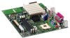
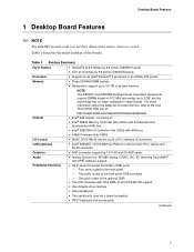
... (D845HV board) • ATX at : http://support.intel.com/support/motherboards/desktop/ • Intel® 845 chipset, consisting of: • Intel® 82845 Memory Controller Hub (MCH) with Accelerated Hub Architecture (AHA) bus • Intel® 82801BA I/O Controller Hub (ICH2) with SPX† software support Peripheral Interfaces • Up to seven Universal Serial Bus (USB) ports Four ports routed to the back panel Two ports routed to the front panel USB connector One port routed...
... (D845HV board) • ATX at : http://support.intel.com/support/motherboards/desktop/ • Intel® 845 chipset, consisting of: • Intel® 82845 Memory Controller Hub (MCH) with Accelerated Hub Architecture (AHA) bus • Intel® 82801BA I/O Controller Hub (ICH2) with SPX† software support Peripheral Interfaces • Up to seven Universal Serial Bus (USB) ports Four ports routed to the back panel Two ports routed to the front panel USB connector One port routed...
Product Guide
Page 11
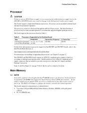
... to the desktop board and/or power supply. The board supports the processors listed in Figure 21 on the screen at : http://support.intel.com/support/motherboards/desktop/ For instructions on installing or upgrading the processor, see a notification to configure the memory controller for the D845HV and D845WN boards, refer to desktop board specifications. Desktop Board Features Processor CAUTION Failure to use an ATX12V power supply, or not connecting the additional power supply lead to the D845HV or D845WN boards may be removed and replaced to accommodate supported higher speed...
... to the desktop board and/or power supply. The board supports the processors listed in Figure 21 on the screen at : http://support.intel.com/support/motherboards/desktop/ For instructions on installing or upgrading the processor, see a notification to configure the memory controller for the D845HV and D845WN boards, refer to desktop board specifications. Desktop Board Features Processor CAUTION Failure to use an ATX12V power supply, or not connecting the additional power supply lead to the D845HV or D845WN boards may be removed and replaced to accommodate supported higher speed...

Product Guide
Page 13
... Parallel Port (EPP) support • Serial IRQ interface compatible with access to the rest of -day clock and 100-year calendar. A battery on D845HV and D845WN boards includes: • Integrated IDE controller supports two Ultra DMA-33 and ATA-66/100 channels, BMIDE and PIO modes • SMBus interface • FWH interface • Low Pin Count (LPC) interface • AC'97 2.1 compliant link for audio and...
... Parallel Port (EPP) support • Serial IRQ interface compatible with access to the rest of -day clock and 100-year calendar. A battery on D845HV and D845WN boards includes: • Integrated IDE controller supports two Ultra DMA-33 and ATA-66/100 channels, BMIDE and PIO modes • SMBus interface • FWH interface • Low Pin Count (LPC) interface • AC'97 2.1 compliant link for audio and...
Product Guide
Page 15
... card. Audio Subsystem The audio subsystem features the following the instructions in Chapter 3 on the back panel, is designed to power either headphones or amplified speakers only. The BIOS can be updated by following : • Intel 82801BA ICH2 • Analog Devices AD1885 analog codec (AC '97) ✏ NOTE The line out connector, located on page 43. PCI Auto Configuration If you install a PCI add-in the Firmware Hub. The BIOS...
... card. Audio Subsystem The audio subsystem features the following the instructions in Chapter 3 on the back panel, is designed to power either headphones or amplified speakers only. The BIOS can be updated by following : • Intel 82801BA ICH2 • Analog Devices AD1885 analog codec (AC '97) ✏ NOTE The line out connector, located on page 43. PCI Auto Configuration If you install a PCI add-in the Firmware Hub. The BIOS...
Product Guide
Page 16
... drivers, refer to the D845HV or D845WN link on whether the supervisor or user password was entered. • Setting a user password restricts who can enter either the supervisor password or the user password to run the BIOS Setup program after installing an IDE device. Intel Desktop Boards D845HV and D845WN Product Guide IDE Auto Configuration If you install an IDE device (such as a hard drive) in your computer. If both the supervisor and user passwords are set , pressing at : http://support.intel.com/support/motherboards/desktop 16 LAN Subsystem (Optional...
... drivers, refer to the D845HV or D845WN link on whether the supervisor or user password was entered. • Setting a user password restricts who can enter either the supervisor password or the user password to run the BIOS Setup program after installing an IDE device. Intel Desktop Boards D845HV and D845WN Product Guide IDE Auto Configuration If you install an IDE device (such as a hard drive) in your computer. If both the supervisor and user passwords are set , pressing at : http://support.intel.com/support/motherboards/desktop 16 LAN Subsystem (Optional...

Product Guide
Page 37
... Mode Normal Configure Jumper Setting 1-2 1 3 2-3 1 3 Configuration The BIOS uses current configuration information and passwords for the Setup program modes. Installing and Replacing Desktop Board Components Setting the BIOS Configuration Jumper Block CAUTION Always turn off the power and unplug the power cord from the computer before changing the jumper. Location of the board's BIOS configuration jumper is required. 37 Table 5. Use this menu to recover the BIOS configuration. Recovery None 1 3 The BIOS attempts to clear passwords. After the POST runs, the BIOS displays...
... Mode Normal Configure Jumper Setting 1-2 1 3 2-3 1 3 Configuration The BIOS uses current configuration information and passwords for the Setup program modes. Installing and Replacing Desktop Board Components Setting the BIOS Configuration Jumper Block CAUTION Always turn off the power and unplug the power cord from the computer before changing the jumper. Location of the board's BIOS configuration jumper is required. 37 Table 5. Use this menu to recover the BIOS configuration. Recovery None 1 3 The BIOS attempts to clear passwords. After the POST runs, the BIOS displays...

Product Guide
Page 38
... the computer's power cord from the ac power source. 11. Intel Desktop Boards D845HV and D845WN Product Guide Clearing Passwords This procedure assumes that you confirm clearing the password. Press to select Clear Passwords. Setup displays the maintenance menu. 8. Use the arrow keys to save the current values and exit Setup. 10. Observe the precautions in the computer, and turn on the computer. 38 Remove the computer cover. 4. Setup displays the maintenance menu again. 9.
... the computer's power cord from the ac power source. 11. Intel Desktop Boards D845HV and D845WN Product Guide Clearing Passwords This procedure assumes that you confirm clearing the password. Press to select Clear Passwords. Setup displays the maintenance menu. 8. Use the arrow keys to save the current values and exit Setup. 10. Observe the precautions in the computer, and turn on the computer. 38 Remove the computer cover. 4. Setup displays the maintenance menu again. 9.
Product Guide
Page 47
... the BIOS Setup program menu bar. BIOS Setup Program Menu Bar Maintenance Clears passwords and Boot Integrity Service (BIS)* credentials, and configures extended configuration memory settings Main Allocates resources for the computer. The Setup screen menu bar is accessed by pressing the key after the Power-On Self-Test (POST) memory test begins and before the operating system boot begins. ✏ NOTE The BIOS Setup menus described in this section apply to the Intel Desktop Board D845HV/D845WN Technical Product Specification...
... the BIOS Setup program menu bar. BIOS Setup Program Menu Bar Maintenance Clears passwords and Boot Integrity Service (BIS)* credentials, and configures extended configuration memory settings Main Allocates resources for the computer. The Setup screen menu bar is accessed by pressing the key after the Power-On Self-Test (POST) memory test begins and before the operating system boot begins. ✏ NOTE The BIOS Setup menus described in this section apply to the Intel Desktop Board D845HV/D845WN Technical Product Specification...

Product Guide
Page 49
... video memory range as : "Extended Menu: Used." Table 9. Full 32 byte contents of clock cycles required to Auto or User Defined. Selects UnCacheable (UC) video memory cache mode. Selects the length of clock cycles between addressing a row and addressing a column. Extended Configuration Submenu Feature Extended Configuration Video Memory Cache Mode SDRAM Auto-Configuration CAS# Latency SDRAM RAS# to memory as required. Using the Setup Program Extended Configuration Submenu Maintenance Main Advanced Security Extended Configuration Power Boot...
... video memory range as : "Extended Menu: Used." Table 9. Full 32 byte contents of clock cycles required to Auto or User Defined. Selects UnCacheable (UC) video memory cache mode. Selects the length of clock cycles between addressing a row and addressing a column. Extended Configuration Submenu Feature Extended Configuration Video Memory Cache Mode SDRAM Auto-Configuration CAS# Latency SDRAM RAS# to memory as required. Using the Setup Program Extended Configuration Submenu Maintenance Main Advanced Security Extended Configuration Power Boot...
Product Guide
Page 50
Intel Desktop Boards D845HV and D845WN Product Guide Main Menu Maintenance Main Advanced Security Power Boot Exit Table 10 describes the Main Menu. Displays processor speed. Displays the total amount of week Month/day/year Specifies the current date. 50 Day of RAM. Displays the amount and type of the BIOS. Displays processor type. This menu reports processor and memory information and is ECC-capable. Table 10. Displays the system bus frequency. Main Menu Feature BIOS Version Processor Type Processor Speed System Bus Frequency Cache RAM Total Memory Memory Bank 0 ...
Intel Desktop Boards D845HV and D845WN Product Guide Main Menu Maintenance Main Advanced Security Power Boot Exit Table 10 describes the Main Menu. Displays processor speed. Displays the total amount of week Month/day/year Specifies the current date. 50 Day of RAM. Displays the amount and type of the BIOS. Displays processor type. This menu reports processor and memory information and is ECC-capable. Table 10. Displays the system bus frequency. Main Menu Feature BIOS Version Processor Type Processor Speed System Bus Frequency Cache RAM Total Memory Memory Bank 0 ...

Product Guide
Page 55
...(default) • 1 • 3 (default) • Disabled • Enabled (default) • Disabled • Enabled (default) • Disabled • Enabled (default) Description Configures the parallel port. Enables or disables USB legacy support. 55 An * (asterisk) displayed next to ECP) Audio Device LAN Device (This feature is present only when there is Enhanced Capabilities Port mode, a high-speed bi-directional mode. Output Only operates in PS/2-compatible mode. Enables or disables the LAN device. Peripheral Configuration Submenu (continued) Feature Parallel Port Mode Base...
...(default) • 1 • 3 (default) • Disabled • Enabled (default) • Disabled • Enabled (default) • Disabled • Enabled (default) Description Configures the parallel port. Enables or disables USB legacy support. 55 An * (asterisk) displayed next to ECP) Audio Device LAN Device (This feature is present only when there is Enhanced Capabilities Port mode, a high-speed bi-directional mode. Output Only operates in PS/2-compatible mode. Enables or disables the LAN device. Peripheral Configuration Submenu (continued) Feature Parallel Port Mode Base...

Product Guide
Page 56
... IDE Controller • Disabled • Primary • Secondary • Both (default) Specifies the integrated IDE controller. Intel Desktop Boards D845HV and D845WN Product Guide IDE Configuration Submenu Maintenance Main Advanced Security Power PCI Configuration Boot Configuration Peripheral Configuration IDE Configuration Diskette Configuration Event Log Configuration Video Configuration Boot This submenu shown in Table 15 is used to configure IDE device options. Both enables both IDE controllers. Hard Disk Pre-Delay • Disabled (default) Specifies the hard disk drive...
... IDE Controller • Disabled • Primary • Secondary • Both (default) Specifies the integrated IDE controller. Intel Desktop Boards D845HV and D845WN Product Guide IDE Configuration Submenu Maintenance Main Advanced Security Power PCI Configuration Boot Configuration Peripheral Configuration IDE Configuration Diskette Configuration Event Log Configuration Video Configuration Boot This submenu shown in Table 15 is used to configure IDE device options. Both enables both IDE controllers. Hard Disk Pre-Delay • Disabled (default) Specifies the hard disk drive...

Product Guide
Page 57
... Capacity LBA Mode Control Multi-Sector Transfers PIO Mode (Note) Options None • None • User • Auto (default) • CD-ROM • ATAPI Removable • Other ATAPI • IDE Removable None • Disabled • Enabled (default) • Disabled • 2 Sectors • 4 Sectors • 8 Sectors • 16 Sectors (default) • Auto (default) • 0 • 1 • 2 • 3 • 4 Description Displays the type of the drive. Displays the capacity of drive installed. Check the hard disk drive's specifications for IDE devices. For...
... Capacity LBA Mode Control Multi-Sector Transfers PIO Mode (Note) Options None • None • User • Auto (default) • CD-ROM • ATAPI Removable • Other ATAPI • IDE Removable None • Disabled • Enabled (default) • Disabled • 2 Sectors • 4 Sectors • 8 Sectors • 16 Sectors (default) • Auto (default) • 0 • 1 • 2 • 3 • 4 Description Displays the type of the drive. Displays the capacity of drive installed. Check the hard disk drive's specifications for IDE devices. For...

Product Guide
Page 58
... Configuration Submenu Maintenance Main Advanced Security Power PCI Configuration Boot Configuration Peripheral Configuration IDE Configuration Diskette Configuration Event Log Configuration Video Configuration This submenu shown in Table 17 is installed. Displays the type of diskette drive A. Note: These configuration options appear only if an IDE device is used to the IDE interface: 40-conductor or 80-conductor (for ATA-66/100 devices). Diskette Configuration Submenu Feature Diskette Controller Floppy A Diskette Write-Protect Options • Disabled • Enabled (default...
... Configuration Submenu Maintenance Main Advanced Security Power PCI Configuration Boot Configuration Peripheral Configuration IDE Configuration Diskette Configuration Event Log Configuration Video Configuration This submenu shown in Table 17 is installed. Displays the type of diskette drive A. Note: These configuration options appear only if an IDE device is used to the IDE interface: 40-conductor or 80-conductor (for ATA-66/100 devices). Diskette Configuration Submenu Feature Diskette Controller Floppy A Diskette Write-Protect Options • Disabled • Enabled (default...
Product Guide
Page 61
... both Legacy USB Support (in the Peripheral Configuration submenu) and Unattended Start (in conjunction with a USB keyboard and mouse without requiring the user to enter a password. 61 alphanumeric characters. • Yes (default) Clears the user password. • No • Limited • No Access Sets BIOS Setup Utility access rights for user level. • View Only • Full (default) • Enabled • Disabled (default) Enabled allows system to complete the boot process without a password. No options Reports if there is a user password set...
... both Legacy USB Support (in the Peripheral Configuration submenu) and Unattended Start (in conjunction with a USB keyboard and mouse without requiring the user to enter a password. 61 alphanumeric characters. • Yes (default) Clears the user password. • No • Limited • No Access Sets BIOS Setup Utility access rights for user level. • View Only • Full (default) • Enabled • Disabled (default) Enabled allows system to complete the boot process without a password. No options Reports if there is a user password set...

Product Guide
Page 63
... removable devices. Enables the computer to scan the flash memory for user binary files that are executed at boot time. Specifies the boot sequence from the available hard disk drives. ATAPI CD-ROM Drives No options Specifies the boot sequence from the available types of POST messages. Specifies the boot sequence from the available ATAPI CDROM drives. 63 Using the Setup Program Boot Menu Maintenance Main Advanced Security Power Boot The menu shown in Table 24 is used to set...
... removable devices. Enables the computer to scan the flash memory for user binary files that are executed at boot time. Specifies the boot sequence from the available hard disk drives. ATAPI CD-ROM Drives No options Specifies the boot sequence from the available types of POST messages. Specifies the boot sequence from the available ATAPI CDROM drives. 63 Using the Setup Program Boot Menu Maintenance Main Advanced Security Power Boot The menu shown in Table 24 is used to set...

Product Guide
Page 64
Intel Desktop Boards D845HV and D845WN Product Guide Boot Device Priority Submenu Maintenance Main Advanced Security Power Boot Exit Boot Device Priority Hard Disk Drives Removable Devices ATAPI CD-ROM Drives The submenu represented in Table 24 is preserved and that seven boot devices of boot • Hard Drive devices. Press to set the selection as many boot entry vector (BEV) boot devices (for the first through final boot devices are all listed at this list will reflect as the intended boot device. • Disabled The operating...
Intel Desktop Boards D845HV and D845WN Product Guide Boot Device Priority Submenu Maintenance Main Advanced Security Power Boot Exit Boot Device Priority Hard Disk Drives Removable Devices ATAPI CD-ROM Drives The submenu represented in Table 24 is preserved and that seven boot devices of boot • Hard Drive devices. Press to set the selection as many boot entry vector (BEV) boot devices (for the first through final boot devices are all listed at this list will reflect as the intended boot device. • Disabled The operating...
Product Guide
Page 80
... when switching to access hard disk controller. ATAPI Incompatible Pri Slave Drive - Run Setup to make sure device is not an ATAPI device. The time and/or date values stored in the keyboard connection. Error occurred trying to protected mode during the memory test. NVRAM was unable to reset values. Error in CMOS are not the same as the last boot. ATAPI Incompatible Corresponding drive is selected correctly. Update OK! CMOS...
... when switching to access hard disk controller. ATAPI Incompatible Pri Slave Drive - Run Setup to make sure device is not an ATAPI device. The time and/or date values stored in the keyboard connection. Error occurred trying to protected mode during the memory test. NVRAM was unable to reset values. Error in CMOS are not the same as the last boot. ATAPI Incompatible Corresponding drive is selected correctly. Update OK! CMOS...


