
Product Guide
Page 5
...RM Mounting Holes 25 8. Installing a Memory Module 30 12. Back Panel Connectors 68 20. Connecting the Processor Fan Heatsink Cable to the Board 26 9. Removing the Battery 41 19. D845WN Board Components 10 3. D845WN Board Mounting Holes 24 7. AGP Card with Retention Notch 32 13... Fan Connector .........28 11. Removing the AGP Card 34 15. Contents 5 Technical Reference Board Connectors ...67 Back Panel Connectors 68 Midboard Connectors 69 Front Panel Connectors 73 Desktop Board Resources 74 Memory Map ...74 DMA Channels ...74 I /O Shield 22 5. Location of ...
...RM Mounting Holes 25 8. Installing a Memory Module 30 12. Back Panel Connectors 68 20. Connecting the Processor Fan Heatsink Cable to the Board 26 9. Removing the Battery 41 19. D845WN Board Components 10 3. D845WN Board Mounting Holes 24 7. AGP Card with Retention Notch 32 13... Fan Connector .........28 11. Removing the AGP Card 34 15. Contents 5 Technical Reference Board Connectors ...67 Back Panel Connectors 68 Midboard Connectors 69 Front Panel Connectors 73 Desktop Board Resources 74 Memory Map ...74 DMA Channels ...74 I /O Shield 22 5. Location of ...
Product Guide
Page 6
...13. Event Log Configuration Submenu 59 19. Boot Menu ...63 24. DMA Channels...74 31. Safety Regulations...83 36. Intel Desktop Boards D845HV and D845WN Product Guide 21. Power and Hardware Control Connectors 70 22. D845HV Board Add-in Card and Peripheral Interface Connectors 72 ...24. Front Panel Connectors 73 Tables 1. RJ-45 LAN Connector LEDs 17 4. Standby Current Requirements 19 5. Jumper Settings for the BIOS...
...13. Event Log Configuration Submenu 59 19. Boot Menu ...63 24. DMA Channels...74 31. Safety Regulations...83 36. Intel Desktop Boards D845HV and D845WN Product Guide 21. Power and Hardware Control Connectors 70 22. D845HV Board Add-in Card and Peripheral Interface Connectors 72 ...24. Front Panel Connectors 73 Tables 1. RJ-45 LAN Connector LEDs 17 4. Standby Current Requirements 19 5. Jumper Settings for the BIOS...
Product Guide
Page 7
...panel USB connector One port routed to the optional CNR • Two IDE interfaces with AHA bus • 4 Mbit Firmware Hub (FWH) • SMSC LPC47M142 low pin count (LPC) interface I /O Control LAN (optional) Graphics Audio • microATX at 9.6 inches by 9.6 inches (D845HV board) • ATX at : http://support.intel.com/support/motherboards... 7 For more information about the latest list of tested memory, refer to the Intel World Wide Web site at 12 inches by 9.6 inches (D845WN board) • Support for illustrations unless otherwise noted. Table 1 describes the major...
...panel USB connector One port routed to the optional CNR • Two IDE interfaces with AHA bus • 4 Mbit Firmware Hub (FWH) • SMSC LPC47M142 low pin count (LPC) interface I /O Control LAN (optional) Graphics Audio • microATX at 9.6 inches by 9.6 inches (D845HV board) • ATX at : http://support.intel.com/support/motherboards... 7 For more information about the latest list of tested memory, refer to the Intel World Wide Web site at 12 inches by 9.6 inches (D845WN board) • Support for illustrations unless otherwise noted. Table 1 describes the major...
Product Guide
Page 8
... shared with PCI bus connector 3) • D845WN board: Six PCI bus add-in card connectors One AGP connector One optional CNR connector (slot shared with PCI bus connector 6) BIOS • Intel/AMI BIOS. • 4 Mbit symmetrical flash...panel Other Features • SCSI hard drive activity LED connector for the front panel • Speaker ✏ NOTE For information about Intel® desktop boards, including technical product specifications, BIOS updates, and device drivers, go to the Intel World Wide Web site at: http://support.intel.com/support/motherboards...
... shared with PCI bus connector 3) • D845WN board: Six PCI bus add-in card connectors One AGP connector One optional CNR connector (slot shared with PCI bus connector 6) BIOS • Intel/AMI BIOS. • 4 Mbit symmetrical flash...panel Other Features • SCSI hard drive activity LED connector for the front panel • Speaker ✏ NOTE For information about Intel® desktop boards, including technical product specifications, BIOS updates, and device drivers, go to the Intel World Wide Web site at: http://support.intel.com/support/motherboards...

Product Guide
Page 9
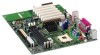
.... A BC D BB E F AA G Z H Y X I W J V K U T SQ N R PO ML OM11978 A CD-ROM connector (ATAPI) O Secondary IDE connector B Auxiliary line-in connector (ATAPI) P Speaker C AGP connector Q Intel 82801BA I/O Controller Hub (ICH2) D Back panel connectors R SCSI hard drive activity LED connector E 12 V processor core voltage connector S Chassis intrusion connector F Rear chassis fan connector (tachometer input) T Front chassis...
.... A BC D BB E F AA G Z H Y X I W J V K U T SQ N R PO ML OM11978 A CD-ROM connector (ATAPI) O Secondary IDE connector B Auxiliary line-in connector (ATAPI) P Speaker C AGP connector Q Intel 82801BA I/O Controller Hub (ICH2) D Back panel connectors R SCSI hard drive activity LED connector E 12 V processor core voltage connector S Chassis intrusion connector F Rear chassis fan connector (tachometer input) T Front chassis...

Product Guide
Page 10
... Guide Figure 2 shows the location of the major components on the D845WN board. A BC D BB E F AA G Z H Y X I W J V K U T SQ N R PO ML OM12039 A CD-ROM connector (ATAPI) O Secondary IDE connector B Auxiliary line-in connector (ATAPI) P Speaker C AGP connector Q Intel 82801BA I/O Controller Hub (ICH2) D Back panel connectors R SCSI hard drive activity LED connector E 12 V processor core voltage...
... Guide Figure 2 shows the location of the major components on the D845WN board. A BC D BB E F AA G Z H Y X I W J V K U T SQ N R PO ML OM12039 A CD-ROM connector (ATAPI) O Secondary IDE connector B Auxiliary line-in connector (ATAPI) P Speaker C AGP connector Q Intel 82801BA I/O Controller Hub (ICH2) D Back panel connectors R SCSI hard drive activity LED connector E 12 V processor core voltage...

Product Guide
Page 14
... to be compatible with PCI bus connector 6) 14 The boards support up to the optional CNR. four ports routed to the back panel, two to the front panel connector, and one to seven USB 1.1 ports via the ICH2 and I/O controller; Use a shielded cable that have the following add... • One AGP connector • One optional CNR connector (slot shared with PCI bus connector 3) The D845WN board has: • Six PCI bus add-in ports. Intel Desktop Boards D845HV and D845WN Product Guide USB Support ✏ NOTE Computer systems that meets the requirements for a full-speed USB device. ...
... to be compatible with PCI bus connector 6) 14 The boards support up to the optional CNR. four ports routed to the back panel, two to the front panel connector, and one to seven USB 1.1 ports via the ICH2 and I/O controller; Use a shielded cable that have the following add... • One AGP connector • One optional CNR connector (slot shared with PCI bus connector 3) The D845WN board has: • Six PCI bus add-in ports. Intel Desktop Boards D845HV and D845WN Product Guide USB Support ✏ NOTE Computer systems that meets the requirements for a full-speed USB device. ...
Product Guide
Page 15
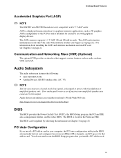
...audio quality may occur if passive (non-amplified) speakers are available from Intel's World Wide Web site: http://support.intel.com/support/motherboards/desktop/ BIOS The BIOS provides the Power-On Self-Test (POST),... (CNR) (Optional) The optional CNR provides an interface that add-in Chapter 3 on the back panel, is intended for that supports various features such as 3D graphics. Audio drivers and utilities are connected to...Board Features Accelerated Graphics Port (AGP) ✏ NOTE The D845HV and D845WN boards are only compatible with retention notches (see Chapter 2 on page 32).
...audio quality may occur if passive (non-amplified) speakers are available from Intel's World Wide Web site: http://support.intel.com/support/motherboards/desktop/ BIOS The BIOS provides the Power-On Self-Test (POST),... (CNR) (Optional) The optional CNR provides an interface that add-in Chapter 3 on the back panel, is intended for that supports various features such as 3D graphics. Audio drivers and utilities are connected to...Board Features Accelerated Graphics Port (AGP) ✏ NOTE The D845HV and D845WN boards are only compatible with retention notches (see Chapter 2 on page 32).

Product Guide
Page 18
... and PCI bus connectors, even when the computer appears to be capable of delivering adequate +5 V standby current. Intel Desktop Boards D845HV and D845WN Product Guide Resume on Ring The operation of Resume on the front panel, the sleep state is standby power to its last known awake state. When signaled by the LED...
... and PCI bus connectors, even when the computer appears to be capable of delivering adequate +5 V standby current. Intel Desktop Boards D845HV and D845WN Product Guide Resume on Ring The operation of Resume on the front panel, the sleep state is standby power to its last known awake state. When signaled by the LED...

Product Guide
Page 21
Some circuitry on the board can provide some ESD protection by wearing an antistatic wrist strap and attaching it to operate even though the front panel power button is off. 21 If such a station is not available, you can continue to a metal part of the procedures described in personal injury or ...
Some circuitry on the board can provide some ESD protection by wearing an antistatic wrist strap and attaching it to operate even though the front panel power button is off. 21 If such a station is not available, you can continue to a metal part of the procedures described in personal injury or ...

Product Guide
Page 34
...lever (D), as shown in Figure 14, until it is completely seated in the AGP connector. 2. Secure the card's metal bracket to the chassis back panel. 2. Removing the AGP Card from the RM: 1. Push back on the card until the retention pin (C) completely clears the notch in the card.... 3. Removing the AGP Card 34 Intel Desktop Boards D845HV and D845WN Product Guide Installing an AGP Card Follow these instructions to remove the AGP card from the Retention Mechanism Follow these instructions to install...
...lever (D), as shown in Figure 14, until it is completely seated in the AGP connector. 2. Secure the card's metal bracket to the chassis back panel. 2. Removing the AGP Card from the RM: 1. Push back on the card until the retention pin (C) completely clears the notch in the card.... 3. Removing the AGP Card 34 Intel Desktop Boards D845HV and D845WN Product Guide Installing an AGP Card Follow these instructions to remove the AGP card from the Retention Mechanism Follow these instructions to install...

Product Guide
Page 67
5 Technical Reference Board Connectors The board connectors can be divided into three groups: • Back panel connectors • Midboard connectors Audio connectors Power and hardware connectors Add-in the load presented by the ... computer, the interconnecting cable, and the external devices themselves. 67 A fault in board and peripheral interface connectors • Front panel connectors CAUTION Many of the midboard and front panel connectors provide operating voltage (+5 V dc and +12 V dc, for powering devices external to devices inside the computer chassis, ...
5 Technical Reference Board Connectors The board connectors can be divided into three groups: • Back panel connectors • Midboard connectors Audio connectors Power and hardware connectors Add-in the load presented by the ... computer, the interconnecting cable, and the external devices themselves. 67 A fault in board and peripheral interface connectors • Front panel connectors CAUTION Many of the midboard and front panel connectors provide operating voltage (+5 V dc and +12 V dc, for powering devices external to devices inside the computer chassis, ...

Product Guide
Page 68
Back Panel Connectors ✏ NOTE The line out connector, located on the board. A E G C BD F Item A B C D E F G H I J K L Description PS/2 mouse port PS/2 keyboard port USB port 0 USB port 1 Parallel ... green Light blue Figure 19. Poor audio quality may occur if passive (non-amplified) speakers are connected to power either headphones or amplified speakers only. Intel Desktop Boards D845HV and D845WN Product Guide Back Panel Connectors Figure 19 shows the back panel connectors on the back panel, is designed to this output. 68
Back Panel Connectors ✏ NOTE The line out connector, located on the board. A E G C BD F Item A B C D E F G H I J K L Description PS/2 mouse port PS/2 keyboard port USB port 0 USB port 1 Parallel ... green Light blue Figure 19. Poor audio quality may occur if passive (non-amplified) speakers are connected to power either headphones or amplified speakers only. Intel Desktop Boards D845HV and D845WN Product Guide Back Panel Connectors Figure 19 shows the back panel connectors on the back panel, is designed to this output. 68

Product Guide
Page 69
Audio Connectors OM11991 69 Midboard Connectors Audio Connectors Figure 20 shows the location of the audio connectors. A BC 4 1 4 1 1 2 9 10 Technical Reference Item A B C Description Color Front panel audio CD-ROM (ATAPI) Auxiliary line in (ATAPI) Black Black White Figure 20.
Audio Connectors OM11991 69 Midboard Connectors Audio Connectors Figure 20 shows the location of the audio connectors. A BC 4 1 4 1 1 2 9 10 Technical Reference Item A B C Description Color Front panel audio CD-ROM (ATAPI) Auxiliary line in (ATAPI) Black Black White Figure 20.

Product Guide
Page 73
Technical Reference 12 9 10 7 10 2 1 1 16 15 2 1 AB C D Item A B C D Description Front panel Alternate power/sleep LED Front panel USB Front panel audio OM11994 Figure 24. Front Panel Connectors 73 Front Panel Connectors Figure 24 shows the location of the front panel connectors.
Technical Reference 12 9 10 7 10 2 1 1 16 15 2 1 AB C D Item A B C D Description Front panel Alternate power/sleep LED Front panel USB Front panel audio OM11994 Figure 24. Front Panel Connectors 73 Front Panel Connectors Figure 24 shows the location of the front panel connectors.


