
Product Guide
Page 3
... and desktop board resources. • A Error Messages and Indicators: information about board layout, component installation, BIOS Setup menus, and regulatory requirements for Intel® Desktop Board D865GBF/D865GLC. Intended Audience The Product Guide is not intended for technically qualified personnel. CAUTION Cautions warn the user about ... Replacing Desktop Board Components: instruction on how to install the desktop board and other hardware components. • 3 Updating the BIOS: instructions on how to update the BIOS. • 4 Using the BIOS Setup Program: contents of data.
... and desktop board resources. • A Error Messages and Indicators: information about board layout, component installation, BIOS Setup menus, and regulatory requirements for Intel® Desktop Board D865GBF/D865GLC. Intended Audience The Product Guide is not intended for technically qualified personnel. CAUTION Cautions warn the user about ... Replacing Desktop Board Components: instruction on how to install the desktop board and other hardware components. • 3 Updating the BIOS: instructions on how to update the BIOS. • 4 Using the BIOS Setup Program: contents of data.

Product Guide
Page 6
Intel Desktop Boards D865GBF/D865GLC Product Guide Place Battery Marking 29 Use Only for Intended Applications 29 Installing the I/O Shield...30 Installing and Removing the Desktop Board 31 Installing and ... Clearing Passwords ...47 Replacing the Battery ...48 3 Updating the BIOS Updating the BIOS with the Intel® Express BIOS Update Utility 53 Updating the BIOS with the Iflash Memory Update Utility 54 Obtaining the BIOS Update File 54 Updating the BIOS...54 Recovering the BIOS 55 4 Using the BIOS Setup Program Maintenance Menu...58 Main Menu ...59 Advanced Menu...
Intel Desktop Boards D865GBF/D865GLC Product Guide Place Battery Marking 29 Use Only for Intended Applications 29 Installing the I/O Shield...30 Installing and Removing the Desktop Board 31 Installing and ... Clearing Passwords ...47 Replacing the Battery ...48 3 Updating the BIOS Updating the BIOS with the Intel® Express BIOS Update Utility 53 Updating the BIOS with the Iflash Memory Update Utility 54 Obtaining the BIOS Update File 54 Updating the BIOS...54 Recovering the BIOS 55 4 Using the BIOS Setup Program Maintenance Menu...58 Main Menu ...59 Advanced Menu...
Product Guide
Page 8
.... PCI Configuration Submenu 61 18. USB Configuration Submenu 71 26. Boot Device Priority Submenu 80 34. DMA Channels...89 40. Intel Desktop Boards D865GBF/D865GLC Product Guide 16. Location of the BIOS Configuration Jumper Block 46 17. PCI Bus Add-in Card and Peripheral Interface Connectors 88 Tables 1. Video Configuration Submenu 70 25...
.... PCI Configuration Submenu 61 18. USB Configuration Submenu 71 26. Boot Device Priority Submenu 80 34. DMA Channels...89 40. Intel Desktop Boards D865GBF/D865GLC Product Guide 16. Location of the BIOS Configuration Jumper Block 46 17. PCI Bus Add-in Card and Peripheral Interface Connectors 88 Tables 1. Video Configuration Submenu 70 25...
Product Guide
Page 12
...• Up to six PCI bus add-in card connectors (SMBus routed to PCI bus 2) • One AGP connector BIOS • Intel/AMI BIOS • 4 Mbit symmetrical flash memory • Support for SMBIOS Power Management • Support for Advanced Configuration and Power ... out of range values Related Links: For more information about Intel Desktop Board D865GBF/D865GLC, including the Technical Product Specification (TPS), BIOS updates, and device drivers, go to the back panel - Intel Desktop Boards D865GBF/D865GLC Product Guide Table 2. Feature Summary (continued) Peripheral Interfaces &#...
...• Up to six PCI bus add-in card connectors (SMBus routed to PCI bus 2) • One AGP connector BIOS • Intel/AMI BIOS • 4 Mbit symmetrical flash memory • Support for SMBIOS Power Management • Support for Advanced Configuration and Power ... out of range values Related Links: For more information about Intel Desktop Board D865GBF/D865GLC, including the Technical Product Specification (TPS), BIOS updates, and device drivers, go to the back panel - Intel Desktop Boards D865GBF/D865GLC Product Guide Table 2. Feature Summary (continued) Peripheral Interfaces &#...
Product Guide
Page 15
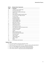
...Front chassis fan connector (fan speed control) Chassis intrusion header Serial ATA connectors Speaker BIOS configuration jumper Alternate power/sleep LED header Front panel header USB 2.0 header Intel 82801EB (ICH5) USB 2.0 header Battery PCI bus add-in card connectors Related Links...following links for the latest information about: • Intel Desktop Board D865GBF/D865GLC, http://www.intel.com/design/motherbd • processors, http://support.intel.com/support/motherboards/desktop • audio software and utilities, http://www.intel.com/design/motherbd • LAN software and drivers, ...
...Front chassis fan connector (fan speed control) Chassis intrusion header Serial ATA connectors Speaker BIOS configuration jumper Alternate power/sleep LED header Front panel header USB 2.0 header Intel 82801EB (ICH5) USB 2.0 header Battery PCI bus add-in card connectors Related Links...following links for the latest information about: • Intel Desktop Board D865GBF/D865GLC, http://www.intel.com/design/motherbd • processors, http://support.intel.com/support/motherboards/desktop • audio software and utilities, http://www.intel.com/design/motherbd • LAN software and drivers, ...

Product Guide
Page 20
...and four routed to USB 1.1 operation. LAN link is communicating with another computer on the LAN. The computer is established. Intel Desktop Boards D865GBF/D865GLC Product Guide RJ-45 LAN Connector LEDs Two LEDs are backward compatible with USB 1.1 devices. Table 7. Disabling Hi-Speed USB... in the BIOS reverts all USB 2.0 ports to the internal USB 2.0 headers. Table 6. USB 2.0 support requires both an operating system and ...
...and four routed to USB 1.1 operation. LAN link is communicating with another computer on the LAN. The computer is established. Intel Desktop Boards D865GBF/D865GLC Product Guide RJ-45 LAN Connector LEDs Two LEDs are backward compatible with USB 1.1 devices. Table 7. Disabling Hi-Speed USB... in the BIOS reverts all USB 2.0 ports to the internal USB 2.0 headers. Table 6. USB 2.0 support requires both an operating system and ...

Product Guide
Page 21
...system device drivers 21 PCI Auto Configuration If you install a PCI add-in card in card. You do not need to run the BIOS Setup program after installing an IDE device. The AGP 3.0 connector supports 8x, 4x, and 1x AGP cards. You do not need to... protocols • Laser Servo (LS-120) drives Accelerated Graphics Port (AGP) NOTE Desktop Board D865GBF/D865GLC is not mechanically compatible with 0.8 V and 1.5 V AGP cards. You can be updated by specifying manual configuration in the BIOS Setup program. The interface supports: • Up to install a legacy 3.3 V AGP card. IDE...
...system device drivers 21 PCI Auto Configuration If you install a PCI add-in card in card. You do not need to run the BIOS Setup program after installing an IDE device. The AGP 3.0 connector supports 8x, 4x, and 1x AGP cards. You do not need to... protocols • Laser Servo (LS-120) drives Accelerated Graphics Port (AGP) NOTE Desktop Board D865GBF/D865GLC is not mechanically compatible with 0.8 V and 1.5 V AGP cards. You can be updated by specifying manual configuration in the BIOS Setup program. The interface supports: • Up to install a legacy 3.3 V AGP card. IDE...

Product Guide
Page 22
... operating system that detects if the chassis cover has been removed. Power Management Features Power management is booted. Intel Desktop Boards D865GBF/D865GLC Product Guide Security Passwords The BIOS includes security features that restrict whether the BIOS Setup program can be connected to the chassis intrusion header on the desktop board. A supervisor password and...
... operating system that detects if the chassis cover has been removed. Power Management Features Power management is booted. Intel Desktop Boards D865GBF/D865GLC Product Guide Security Passwords The BIOS includes security features that restrict whether the BIOS Setup program can be connected to the chassis intrusion header on the desktop board. A supervisor password and...
Product Guide
Page 46
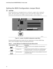
... After the Power-On Self-Test (POST) runs, the BIOS displays the Maintenance Menu. Use this menu to be done in BIOS Setup. The location of a failed BIOS update. 46 Location of the BIOS Configuration Jumper Block The three-pin BIOS jumper block enables all board configurations to clear passwords. 1 ... modes. Moving the jumper with the power on may result in unreliable computer operation. Table 11. Intel Desktop Boards D865GBF/D865GLC Product Guide Setting the BIOS Configuration Jumper Block CAUTION Always turn off the power and unplug the power cord from a recovery diskette...
... After the Power-On Self-Test (POST) runs, the BIOS displays the Maintenance Menu. Use this menu to be done in BIOS Setup. The location of a failed BIOS update. 46 Location of the BIOS Configuration Jumper Block The three-pin BIOS jumper block enables all board configurations to clear passwords. 1 ... modes. Moving the jumper with the power on may result in unreliable computer operation. Table 11. Intel Desktop Boards D865GBF/D865GLC Product Guide Setting the BIOS Configuration Jumper Block CAUTION Always turn off the power and unplug the power cord from a recovery diskette...
Product Guide
Page 48
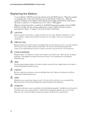
... date and time) might not be accurate. Paristot on kierrätettävä, jos se on väärä. Intel Desktop Boards D865GBF/D865GLC Product Guide Replacing the Battery A coin-cell battery (CR2032) powers the real-time clock and CMOS memory. Batterier ska kasseras ...tyyppi on mahdollista. Entsorgen Sie verbrauchte Batterien den Anweisungen des Herstellers entsprechend. 48 When the voltage drops below a certain level, the BIOS Setup program settings stored in , the standby current from the power supply extends the life of used batteries must be recycled where ...
... date and time) might not be accurate. Paristot on kierrätettävä, jos se on väärä. Intel Desktop Boards D865GBF/D865GLC Product Guide Replacing the Battery A coin-cell battery (CR2032) powers the real-time clock and CMOS memory. Batterier ska kasseras ...tyyppi on mahdollista. Entsorgen Sie verbrauchte Batterien den Anweisungen des Herstellers entsprechend. 48 When the voltage drops below a certain level, the BIOS Setup program settings stored in , the standby current from the power supply extends the life of used batteries must be recycled where ...
Product Guide
Page 53
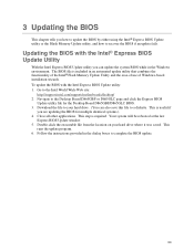
.... 53 Follow the instructions provided in the Windows environment. 3 Updating the BIOS This chapter tells you are updating the BIOS for the Desktop Board D865GBF/D865GLC BIOS. 3. This step is included in an automated update utility that combines the functionality of the Intel® Flash Memory Update Utility and the ease-of use of Windows...
.... 53 Follow the instructions provided in the Windows environment. 3 Updating the BIOS This chapter tells you are updating the BIOS for the Desktop Board D865GBF/D865GLC BIOS. 3. This step is included in an automated update utility that combines the functionality of the Intel® Flash Memory Update Utility and the ease-of use of Windows...
Product Guide
Page 54
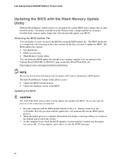
... Update Utility allows you need to update the BIOS. Boot the computer with the BIOS update diskette in flash memory • Update the language section of the BIOS by navigating to the Desktop Board D865GBF or D865GLC page on the Intel World Wide Web site: http://support.intel.com/support/motherboards/desktop NOTE Review the instructions...
... Update Utility allows you need to update the BIOS. Boot the computer with the BIOS update diskette in flash memory • Update the language section of the BIOS by navigating to the Desktop Board D865GBF or D865GLC page on the Intel World Wide Web site: http://support.intel.com/support/motherboards/desktop NOTE Review the instructions...
Product Guide
Page 57
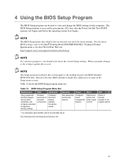
...; Desktop Board D865GBF/D865GLC Technical Product Specification or the Intel World Wide Web site: http://support.intel.com/support/motherboards/desktop NOTE For reference purposes, you make changes to the settings, update this section may not show the latest settings. BIOS Setup Program Menu Bar Maintenance Main Advanced Security Power Boot Exit Clears passwords...
...; Desktop Board D865GBF/D865GLC Technical Product Specification or the Intel World Wide Web site: http://support.intel.com/support/motherboards/desktop NOTE For reference purposes, you make changes to the settings, update this section may not show the latest settings. BIOS Setup Program Menu Bar Maintenance Main Advanced Security Power Boot Exit Clears passwords...
Product Guide
Page 58
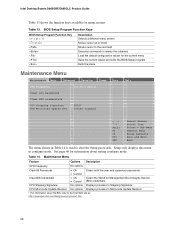
See page 46 for the current menu Save the current values and exits the BIOS Setup program Exits the menu Maintenance Menu Maintenance Main Advanced Security Power CPU Frequency [13 To 1 Ratio] Clear All Passwords Clear BIS... Update Revision. * For information about setting configure mode. CPU Stepping Signature No options Displays processor's Stepping Signature. Table 13. Table 14. Intel Desktop Boards D865GBF/D865GLC Product Guide Table 13 shows the function keys available for Management Boot Integrity Service • Cancel (BIS) credentials. Setup only displays this menu...
See page 46 for the current menu Save the current values and exits the BIOS Setup program Exits the menu Maintenance Menu Maintenance Main Advanced Security Power CPU Frequency [13 To 1 Ratio] Clear All Passwords Clear BIS... Update Revision. * For information about setting configure mode. CPU Stepping Signature No options Displays processor's Stepping Signature. Table 13. Table 14. Intel Desktop Boards D865GBF/D865GLC Product Guide Table 13 shows the function keys available for Management Boot Integrity Service • Cancel (BIS) credentials. Setup only displays this menu...

Product Guide
Page 62
Yes lets the operating system configure Plug & Play (PnP) devices not required for use during lab testing. This option is desired. Intel Desktop Boards D865GBF/D865GLC Product Guide Boot Configuration Submenu Main Advanced Security Power Boot Exit Boot Configuration Plug & Play O/S Numlock [No] [On] m o n p Enter F1 P9 F10 ESC Select Screen.... This setting is used to set the Plug & Play options and the power-on the numeric keypad of the Numlock key. No lets the BIOS configure all devices in Table 18 is appropriate when using a Plug and Play operating system. Table 18.
Yes lets the operating system configure Plug & Play (PnP) devices not required for use during lab testing. This option is desired. Intel Desktop Boards D865GBF/D865GLC Product Guide Boot Configuration Submenu Main Advanced Security Power Boot Exit Boot Configuration Plug & Play O/S Numlock [No] [On] m o n p Enter F1 P9 F10 ESC Select Screen.... This setting is used to set the Plug & Play options and the power-on the numeric keypad of the Numlock key. No lets the BIOS configure all devices in Table 18 is appropriate when using a Plug and Play operating system. Table 18.

Product Guide
Page 66
...ATAPI device. For brevity, only one example is shown. Displays the capacity of the drive. Specifies the PIO mode. Intel Desktop Boards D865GBF/D865GLC Product Guide PATA and SATA Submenus Main Advanced Security Power Boot Exit ` [SATA Port-0 : Xxxxxxxx ] Type Maximum Capacity... [Auto] [Auto] Configuration Options Selected by BIOS LBA Mode : Block Mode: PIO Mode : Ultra DMA : Cable Detected : [Supported] 16 sectors Mode 4 Mode 6...
...ATAPI device. For brevity, only one example is shown. Displays the capacity of the drive. Specifies the PIO mode. Intel Desktop Boards D865GBF/D865GLC Product Guide PATA and SATA Submenus Main Advanced Security Power Boot Exit ` [SATA Port-0 : Xxxxxxxx ] Type Maximum Capacity... [Auto] [Auto] Configuration Options Selected by BIOS LBA Mode : Block Mode: PIO Mode : Ultra DMA : Cable Detected : [Supported] 16 sectors Mode 4 Mode 6...
Product Guide
Page 74
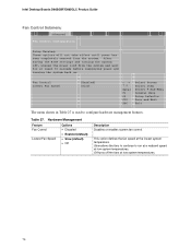
...The menu shown in Table 27 is used to run at a reduced speed at low system temperatures. 74 After saving the BIOS settings and turning the system off the fans at low system temperatures. Slow allows the fans to continue to configure hardware management... • Enabled (default) • Slow (default) • Off Description Disables or enables system fan control. Table 27. Intel Desktop Boards D865GBF/D865GLC Product Guide Fan Control Submenu Main Advanced Security Fan Control Configuration Power Boot Exit Setup Warning: These options will not take effect until...
...The menu shown in Table 27 is used to run at a reduced speed at low system temperatures. 74 After saving the BIOS settings and turning the system off the fans at low system temperatures. Slow allows the fans to continue to configure hardware management... • Enabled (default) • Slow (default) • Off Description Disables or enables system fan control. Table 27. Intel Desktop Boards D865GBF/D865GLC Product Guide Fan Control Submenu Main Advanced Security Fan Control Configuration Power Boot Exit Setup Warning: These options will not take effect until...

Product Guide
Page 76
... the user password. • No • Limited • No access Sets BIOS Setup Utility access rights for user level. • View Only • Full (default) • Disabled (default) • Enabled Enables or disables the chassis intrusion feature. Intel Desktop Boards D865GBF/D865GLC Product Guide Security Menu Main Advanced Security Power Boot Exit Supervisor...
... the user password. • No • Limited • No access Sets BIOS Setup Utility access rights for user level. • View Only • Full (default) • Disabled (default) • Enabled Enables or disables the chassis intrusion feature. Intel Desktop Boards D865GBF/D865GLC Product Guide Security Menu Main Advanced Security Power Boot Exit Supervisor...

Product Guide
Page 80
To specify • Hard Drive boot sequence: • ATAPI CD-ROM 1. Intel Desktop Boards D865GBF/D865GLC Product Guide Boot Device Priority Submenu Main Advanced Security Power Boot Exit 1st Boot Device 2nd Boot Device 3rd Boot Device [1st FLOPPY DRIVE] [xxxxxxxxxxx... has been disabled in Table 33 is for the first through final boot devices are, respectively listed below , with or . • Disabled 2. The BIOS supports up to each boot device in the corresponding type menu. The default settings for setting boot devices priority. A device enclosed in parenthesis has been...
To specify • Hard Drive boot sequence: • ATAPI CD-ROM 1. Intel Desktop Boards D865GBF/D865GLC Product Guide Boot Device Priority Submenu Main Advanced Security Power Boot Exit 1st Boot Device 2nd Boot Device 3rd Boot Device [1st FLOPPY DRIVE] [xxxxxxxxxxx... has been disabled in Table 33 is for the first through final boot devices are, respectively listed below , with or . • Disabled 2. The BIOS supports up to each boot device in the corresponding type menu. The default settings for setting boot devices priority. A device enclosed in parenthesis has been...

Product Guide
Page 82
... from the available devices. Note: This boot device submenu appears only if at least one boot device of removable devices supported by the BIOS. 82 Select the boot device with or . 2. This list will display up to four removable devices, the maximum number of this ...type is for setting removable devices. To specify boot sequence: 1. Intel Desktop Boards D865GBF/D865GLC Product Guide Removable Devices Submenu Main Advanced Security Power Boot Exit 1st Drive [1st FLOPPY DRIVE] Specifies the boot sequence from the...
... from the available devices. Note: This boot device submenu appears only if at least one boot device of removable devices supported by the BIOS. 82 Select the boot device with or . 2. This list will display up to four removable devices, the maximum number of this ...type is for setting removable devices. To specify boot sequence: 1. Intel Desktop Boards D865GBF/D865GLC Product Guide Removable Devices Submenu Main Advanced Security Power Boot Exit 1st Drive [1st FLOPPY DRIVE] Specifies the boot sequence from the...


