
Product Guide
Page 5
......17 BIOS ...17 PCI Auto Configuration 17 SATA/IDE Auto Configuration 17 Security Passwords ...17 Chassis Intrusion...18 Power Management Features 18 ACPI...18 Power Connectors ...18 Fan Connectors...18 Fan Speed Control (Intel® Precision Cooling Technology 18 Suspend to RAM (Instantly Available PC Technology 19 Resume on Ring...19 Wake from USB...19 Wake from PS/2 Keyboard/Mouse 19 PME# Wakeup Support 20 Speaker...20 Battery...20 Real-Time Clock...20 2 Installing and Replacing Desktop Board Components Before You Begin ...21 Installation Precautions ...22 Installation Instructions...
......17 BIOS ...17 PCI Auto Configuration 17 SATA/IDE Auto Configuration 17 Security Passwords ...17 Chassis Intrusion...18 Power Management Features 18 ACPI...18 Power Connectors ...18 Fan Connectors...18 Fan Speed Control (Intel® Precision Cooling Technology 18 Suspend to RAM (Instantly Available PC Technology 19 Resume on Ring...19 Wake from USB...19 Wake from PS/2 Keyboard/Mouse 19 PME# Wakeup Support 20 Speaker...20 Battery...20 Real-Time Clock...20 2 Installing and Replacing Desktop Board Components Before You Begin ...21 Installation Precautions ...22 Installation Instructions...
Product Guide
Page 6
...Internal Headers 33 Connecting the Front Panel Header 34 Connecting the USB 2.0 Header 34 Installing a Front Panel Audio Solution 35 Connecting Hardware Control and Power Cables 36 Connecting the Chassis Intrusion Cable 37 Connecting Fans ...37 Connecting Power Supply Cables 37 Add-In Card and Peripheral Interface Connectors 38 Setting the BIOS Configuration Jumper Block 39 Clearing BIOS Passwords 40 Back Panel Connectors...41 Replacing the Battery ...42 3 Updating the BIOS Updating the BIOS with the Intel® Express BIOS Update Utility 47 Updating the BIOS with the Iflash Memory...
...Internal Headers 33 Connecting the Front Panel Header 34 Connecting the USB 2.0 Header 34 Installing a Front Panel Audio Solution 35 Connecting Hardware Control and Power Cables 36 Connecting the Chassis Intrusion Cable 37 Connecting Fans ...37 Connecting Power Supply Cables 37 Add-In Card and Peripheral Interface Connectors 38 Setting the BIOS Configuration Jumper Block 39 Clearing BIOS Passwords 40 Back Panel Connectors...41 Replacing the Battery ...42 3 Updating the BIOS Updating the BIOS with the Intel® Express BIOS Update Utility 47 Updating the BIOS with the Iflash Memory...
Product Guide
Page 7
... Control Headers and Power Connectors 36 11. Installing a Memory Module 28 7. Location of Mounting Screw Holes 25 4. Jumper Settings for the BIOS Setup Program Modes 39 9. Desktop Board D865GVHZ Components 11 2. Connecting the Processor Fan Heat Sink Cable to the Processor Fan Connector ........27 6. Back Panel Connectors 41 14. Contents Boot Menu...72 Boot Device Priority Submenu 73 Hard Disk Drives Submenu 74 Removable Devices Submenu 75 ATAPI CD-ROM Drives 76 Exit Menu ...77 5 Desktop Board Resources Memory Map ...79 DMA Channels ...79 Interrupts...80 A Error...
... Control Headers and Power Connectors 36 11. Installing a Memory Module 28 7. Location of Mounting Screw Holes 25 4. Jumper Settings for the BIOS Setup Program Modes 39 9. Desktop Board D865GVHZ Components 11 2. Connecting the Processor Fan Heat Sink Cable to the Processor Fan Connector ........27 6. Back Panel Connectors 41 14. Contents Boot Menu...72 Boot Device Priority Submenu 73 Hard Disk Drives Submenu 74 Removable Devices Submenu 75 ATAPI CD-ROM Drives 76 Exit Menu ...77 5 Desktop Board Resources Memory Map ...79 DMA Channels ...79 Interrupts...80 A Error...
Product Guide
Page 9
... card connectors (SMBus routed to PCI bus 2) BIOS • Intel/AMI BIOS • 4 Mbit symmetrical flash memory • Support for SMBIOS Power Management • Support for Advanced Configuration and Power Interface (ACPI) • Suspend to RAM (STR) • Wake on USB, PCI, RS-232, PS/2, LAN, and front panel 9 Four ports routed to two internal USB headers • Two IDE interfaces with Ultra DMA-33 and ATA-66/100 support • Two Serial ATA (SATA) connectors • One diskette drive interface...
... card connectors (SMBus routed to PCI bus 2) BIOS • Intel/AMI BIOS • 4 Mbit symmetrical flash memory • Support for SMBIOS Power Management • Support for Advanced Configuration and Power Interface (ACPI) • Suspend to RAM (STR) • Wake on USB, PCI, RS-232, PS/2, LAN, and front panel 9 Four ports routed to two internal USB headers • Two IDE interfaces with Ultra DMA-33 and ATA-66/100 support • Two Serial ATA (SATA) connectors • One diskette drive interface...
Product Guide
Page 12
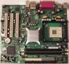
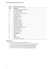
... IDE connector Front chassis fan header BIOS configuration jumper Alternate power/sleep LED header Front panel header Chassis intrusion header Serial ATA connectors USB 2.0 header Intel 82801EB (ICH5) Speaker Battery USB 2.0 header PCI bus add-in card connectors Related Links Go to the following links for the latest information about: • Intel Desktop Board D865GVHZ, http://www.intel.com/design/motherbd • Processors, http://support.intel.com/support/motherboards/desktop • Audio software and utilities, http://www.intel.com/design/motherbd • LAN software and drivers...
... IDE connector Front chassis fan header BIOS configuration jumper Alternate power/sleep LED header Front panel header Chassis intrusion header Serial ATA connectors USB 2.0 header Intel 82801EB (ICH5) Speaker Battery USB 2.0 header PCI bus add-in card connectors Related Links Go to the following links for the latest information about: • Intel Desktop Board D865GVHZ, http://www.intel.com/design/motherbd • Processors, http://support.intel.com/support/motherboards/desktop • Audio software and utilities, http://www.intel.com/design/motherbd • LAN software and drivers...
Product Guide
Page 14
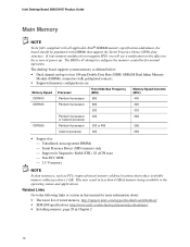
... Dual Inline Memory Module (DIMMs) connectors with DIMMs that reduce available memory addresses above 3 GB. This may result in less than 4 GB of tested memory, http://support.intel.com/support/motherboards/desktop/ • SDRAM specifications, http://www.intel.com/technology/memory/pcsdram/spec/ • Installing memory, page 28 in this effect on the screen at power up to the operating system and applications. The desktop board supports system memory as PCI, require physical memory address locations...
... Dual Inline Memory Module (DIMMs) connectors with DIMMs that reduce available memory addresses above 3 GB. This may result in less than 4 GB of tested memory, http://support.intel.com/support/motherboards/desktop/ • SDRAM specifications, http://www.intel.com/technology/memory/pcsdram/spec/ • Installing memory, page 28 in this effect on the screen at power up to the operating system and applications. The desktop board supports system memory as PCI, require physical memory address locations...
Product Guide
Page 17
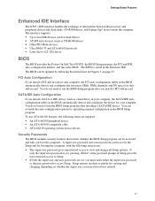
... be updated by specifying manual configuration in Chapter 3 on whether the supervisor or user password was entered. 17 A supervisor password and a user password can boot the computer. If only the supervisor password is stored in card. You do not need to run the BIOS Setup program after installing a SATA/IDE device. You can be set , you install a PCI add-in the Firmware Hub. The BIOS can override the auto-configuration options by following the instructions in the BIOS Setup...
... be updated by specifying manual configuration in Chapter 3 on whether the supervisor or user password was entered. 17 A supervisor password and a user password can boot the computer. If only the supervisor password is stored in card. You do not need to run the BIOS Setup program after installing a SATA/IDE device. You can be set , you install a PCI add-in the Firmware Hub. The BIOS can override the auto-configuration options by following the instructions in the BIOS Setup...
Product Guide
Page 18
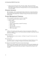
... location of the chassis intrusion header. This feature reduces system fan noise by lowering the speed of the chassis fans connected to RAM (Instantly Available PC technology) Resume on Ring Wake from USB Wake from PS/2 keyboard/mouse PME# wakeup support ACPI ACPI gives the operating system direct control over the power management and Plug & Play functions of a computer. Intel Desktop Board D865GVHZ Product Guide • Setting a user password restricts who can enter either password to the chassis intrusion header on the desktop board. Power...
... location of the chassis intrusion header. This feature reduces system fan noise by lowering the speed of the chassis fans connected to RAM (Instantly Available PC technology) Resume on Ring Wake from USB Wake from PS/2 keyboard/mouse PME# wakeup support ACPI ACPI gives the operating system direct control over the power management and Plug & Play functions of a computer. Intel Desktop Board D865GVHZ Product Guide • Setting a user password restricts who can enter either password to the chassis intrusion header on the desktop board. Power...

Product Guide
Page 19
.../2 keyboard/mouse activity wakes the computer from the PCI and/or USB buses exceeds power supply capacity, the desktop board may lose register settings stored in memory. This feature should be able to provide enough standby current to support multiple wake events from an ACPI S1 or S3 state. 19 When signaled by the LED turning amber. Desktop Board Features The fan speed control feature can be disabled in the BIOS, resulting...
.../2 keyboard/mouse activity wakes the computer from the PCI and/or USB buses exceeds power supply capacity, the desktop board may lose register settings stored in memory. This feature should be able to provide enough standby current to support multiple wake events from an ACPI S1 or S3 state. 19 When signaled by the LED turning amber. Desktop Board Features The fan speed control feature can be disabled in the BIOS, resulting...

Product Guide
Page 35
... the AC power cord. 3. Remove the two jumpers from the header to the front panel audio solution. 7. Installing and Replacing Desktop Board Components Installing a Front Panel Audio Solution Figure 9-A shows the location of the front panel audio header. Remove the cover. 4. Turn off all peripheral devices connected to the computer. Install a correctly keyed and shielded front panel audio cable. 6. Observe the precautions in "Before You Begin" on pins 9-10 (rear L channel). 7. Remove the front panel audio cable. 5. Table 7. Front Panel Audio Header Signal Names Pin Signal...
... the AC power cord. 3. Remove the two jumpers from the header to the front panel audio solution. 7. Installing and Replacing Desktop Board Components Installing a Front Panel Audio Solution Figure 9-A shows the location of the front panel audio header. Remove the cover. 4. Turn off all peripheral devices connected to the computer. Install a correctly keyed and shielded front panel audio cable. 6. Observe the precautions in "Before You Begin" on pins 9-10 (rear L channel). 7. Remove the front panel audio cable. 5. Table 7. Front Panel Audio Header Signal Names Pin Signal...

Product Guide
Page 39
Location of the BIOS Configuration Jumper Block The three-pin BIOS jumper block enables all board configurations to clear passwords. 13 Recovery (None) The BIOS recovers data from the computer before changing the jumper. Table 8 shows the jumper settings for booting. 13 Configure (2-3) After the Power-On Self-Test (POST) runs, the BIOS displays the Maintenance Menu. Use this menu to be done in the event of the desktop board's BIOS configuration jumper is shown in unreliable computer operation. Moving the jumper with the...
Location of the BIOS Configuration Jumper Block The three-pin BIOS jumper block enables all board configurations to clear passwords. 13 Recovery (None) The BIOS recovers data from the computer before changing the jumper. Table 8 shows the jumper settings for booting. 13 Configure (2-3) After the Power-On Self-Test (POST) runs, the BIOS displays the Maintenance Menu. Use this menu to be done in the event of the desktop board's BIOS configuration jumper is shown in unreliable computer operation. Moving the jumper with the...

Product Guide
Page 40
... power source. 11. Place the jumper on page 21. 2. Replace the cover, plug in the computer and the BIOS configuration jumper block is installed in the computer, turn on pins 1-2 as shown below . 13 13. Remove the computer cover. 4. Turn off the computer. Setup displays the Maintenance menu. 8. Setup displays the maintenance menu again. 9. Intel Desktop Board D865GVHZ Product Guide Clearing BIOS Passwords This procedure assumes that you confirm clearing the password. The computer starts the Setup program. Use the arrow keys...
... power source. 11. Place the jumper on page 21. 2. Replace the cover, plug in the computer and the BIOS configuration jumper block is installed in the computer, turn on pins 1-2 as shown below . 13 13. Remove the computer cover. 4. Turn off the computer. Setup displays the Maintenance menu. 8. Setup displays the maintenance menu again. 9. Intel Desktop Board D865GVHZ Product Guide Clearing BIOS Passwords This procedure assumes that you confirm clearing the password. The computer starts the Setup program. Use the arrow keys...
Product Guide
Page 51
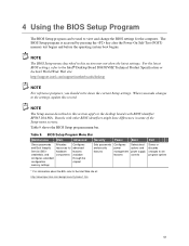
... latest settings. BIOS Setup Program Menu Bar Maintenance Main Advanced Security Power Boot Exit Clears passwords and Boot Integrity Service (BIS)* credentials, and configures extended configuration memory settings Allocates resources for the computer. The BIOS Setup program is accessed by pressing the key after the Power-On Self-Test (POST) memory test begins and before the operating system boot begins. Boards with BIOS identifier BF865.10A.86A. When you make changes to the Intel® Desktop Board D865GVHZ Technical Product Specification...
... latest settings. BIOS Setup Program Menu Bar Maintenance Main Advanced Security Power Boot Exit Clears passwords and Boot Integrity Service (BIS)* credentials, and configures extended configuration memory settings Allocates resources for the computer. The BIOS Setup program is accessed by pressing the key after the Power-On Self-Test (POST) memory test begins and before the operating system boot begins. Boards with BIOS identifier BF865.10A.86A. When you make changes to the Intel® Desktop Board D865GVHZ Technical Product Specification...

Product Guide
Page 53
... Power Boot Exit BIOS Version xxxxx10A.86A.xxxx.xxx Processor Type Hyper-Threading Technology Processor Speed System Bus Speed System Memory Speed Intel® Pentium® 4 [Enabled] X.XX GHz XXX MHz XXX MHz Cache RAM XXX KB Total Memory Memory Mode Memory Channel A Slot 0 Memory Channel A Slot 1 Memory Channel B Slot 0 Memory Channel B Slot 1 XXX MB Dual Channel XXX MB (DDRYYY) Not Installed XXX MB (DDRYYY) Not Installed Language System Time [English] [xx.xx.xx] Enter F1 P9 F10 ESC Select Screen Select Item Select Sub-Menu General Help Setup Defaults...
... Power Boot Exit BIOS Version xxxxx10A.86A.xxxx.xxx Processor Type Hyper-Threading Technology Processor Speed System Bus Speed System Memory Speed Intel® Pentium® 4 [Enabled] X.XX GHz XXX MHz XXX MHz Cache RAM XXX KB Total Memory Memory Mode Memory Channel A Slot 0 Memory Channel A Slot 1 Memory Channel B Slot 0 Memory Channel B Slot 1 XXX MB Dual Channel XXX MB (DDRYYY) Not Installed XXX MB (DDRYYY) Not Installed Language System Time [English] [xx.xx.xx] Enter F1 P9 F10 ESC Select Screen Select Item Select Sub-Menu General Help Setup Defaults...
Product Guide
Page 54
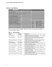
... Options No options Boot Configuration No options Peripheral Configuration No options IDE Configuration Diskette Configuration No options No options Event Log Configuration No options Video Configuration No options USB Configuration No options Chipset Configuration No options Fan Control Configuration No options Description Configures individual PCI slot's IRQ priority. When selected, displays the Diskette Configuration submenu. Intel Desktop Board D865GVHZ Product Guide Advanced Menu Main Advanced Security Power Boot Exit Setup Warning: Setting items on this screen...
... Options No options Boot Configuration No options Peripheral Configuration No options IDE Configuration Diskette Configuration No options No options Event Log Configuration No options Video Configuration No options USB Configuration No options Chipset Configuration No options Fan Control Configuration No options Description Configures individual PCI slot's IRQ priority. When selected, displays the Diskette Configuration submenu. Intel Desktop Board D865GVHZ Product Guide Advanced Menu Main Advanced Security Power Boot Exit Setup Warning: Setting items on this screen...

Product Guide
Page 60
...drive installed. continued 60 Auto fills-in capabilities from ATA/ATAPI device. Intel Desktop Board D865GVHZ Product Guide PATA Submenu Main Advanced Security Power Boot Exit [PATA Port-0 : Xxxxxxxx ] Type Maximum Capacity [Auto] [Auto] Configuration Options Selected by BIOS LBA Mode : Block Mode: PIO Mode : Ultra DMA : Cable Detected : [Supported] 16 sectors Mode 4 Mode 6 Serial Enter F1 P9 F10 ESC Select Screen Select Item Select Sub-Menu General Help Setup Defaults Save and Exit Exit There are not supported on desktop board D865GVHZ. NOTE: SATA hard drives are four IDE...
...drive installed. continued 60 Auto fills-in capabilities from ATA/ATAPI device. Intel Desktop Board D865GVHZ Product Guide PATA Submenu Main Advanced Security Power Boot Exit [PATA Port-0 : Xxxxxxxx ] Type Maximum Capacity [Auto] [Auto] Configuration Options Selected by BIOS LBA Mode : Block Mode: PIO Mode : Ultra DMA : Cable Detected : [Supported] 16 sectors Mode 4 Mode 6 Serial Enter F1 P9 F10 ESC Select Screen Select Item Select Sub-Menu General Help Setup Defaults Save and Exit Exit There are not supported on desktop board D865GVHZ. NOTE: SATA hard drives are four IDE...

Product Guide
Page 66
...• Auto (default) • Disable • No (default) • Continue • Default (default) • -2.0% • -1.0% • +1.0% • +2.0% • +3.0% • +4.0% Description Some older expansion devices require this screen to incorrect values may cause your system to malfunction! Set PCI latency time. Alters host and I/O clock frequencies. Intel Desktop Board D865GVHZ Product Guide Chipset Configuration Submenu Main Advanced Security Power Boot Exit Chipset Configuration Setup Warning: Setting items on this option to be enabled. ISA Enable Bit PCI Latency...
...• Auto (default) • Disable • No (default) • Continue • Default (default) • -2.0% • -1.0% • +1.0% • +2.0% • +3.0% • +4.0% Description Some older expansion devices require this screen to incorrect values may cause your system to malfunction! Set PCI latency time. Alters host and I/O clock frequencies. Intel Desktop Board D865GVHZ Product Guide Chipset Configuration Submenu Main Advanced Security Power Boot Exit Chipset Configuration Setup Warning: Setting items on this option to be enabled. ISA Enable Bit PCI Latency...
Product Guide
Page 69
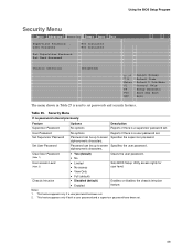
.... Using the BIOS Setup Program Security Menu Main Advanced Security Power Boot Exit Supervisor Password : User Password : Not Installed Not Installed Set Supervisor Password Set User Password Chassis Intrusion [Disabled] Enter F1 P9 F10 ESC Select Screen Select Item Select Sub-Menu General Help Setup Defaults Save and Exit Exit The menu shown in Table 25 is used to set . User Password No options Reports if there is a supervisor password set. User access Level (Note 2) • Limited • No access • View Only Sets BIOS Setup Utility access rights for user...
.... Using the BIOS Setup Program Security Menu Main Advanced Security Power Boot Exit Supervisor Password : User Password : Not Installed Not Installed Set Supervisor Password Set User Password Chassis Intrusion [Disabled] Enter F1 P9 F10 ESC Select Screen Select Item Select Sub-Menu General Help Setup Defaults Save and Exit Exit The menu shown in Table 25 is used to set . User Password No options Reports if there is a supervisor password set. User access Level (Note 2) • Limited • No access • View Only Sets BIOS Setup Utility access rights for user...

Product Guide
Page 72
... Removable Devices ATAPI CD-ROM Drives Options Description • Disabled Disabled displays normal POST messages. • Enabled (default) Enabled displays OEM logo instead of boot devices. Intel Desktop Board D865GVHZ Product Guide Boot Menu Main Advanced Security Power Boot Exit Silent BOOT Intel ® Rapid BIOS Boot Scan User Flash Area PXE Boot to LAN USB Boot [Enabled] [Enabled] [Enabled] [Disabled] [Enabled] Boot Device Priority Hard Disk Drives Removable Devices ATAPI CD-ROM Drives Enter F1 P9 F10 ESC Select Screen Select Item Select Sub-Menu General Help Setup Defaults...
... Removable Devices ATAPI CD-ROM Drives Options Description • Disabled Disabled displays normal POST messages. • Enabled (default) Enabled displays OEM logo instead of boot devices. Intel Desktop Board D865GVHZ Product Guide Boot Menu Main Advanced Security Power Boot Exit Silent BOOT Intel ® Rapid BIOS Boot Scan User Flash Area PXE Boot to LAN USB Boot [Enabled] [Enabled] [Enabled] [Disabled] [Enabled] Boot Device Priority Hard Disk Drives Removable Devices ATAPI CD-ROM Drives Enter F1 P9 F10 ESC Select Screen Select Item Select Sub-Menu General Help Setup Defaults...

Product Guide
Page 74
... Help Setup Defaults Save and Exit Exit The submenu shown in Table 30 is installed. ARMD = ATAPI Removable Media Device. Table 30. To specify boot sequence: 1. Press Enter to set the selection as the intended boot device. This list will display up to set the selections as the intended boot device. Press to 12 hard disk drives, the maximum number of this type is for setting hard disk drives. Intel Desktop Board D865GVHZ Product Guide Hard Disk Drives Submenu Main Advanced Security Power Boot...
... Help Setup Defaults Save and Exit Exit The submenu shown in Table 30 is installed. ARMD = ATAPI Removable Media Device. Table 30. To specify boot sequence: 1. Press Enter to set the selection as the intended boot device. This list will display up to set the selections as the intended boot device. Press to 12 hard disk drives, the maximum number of this type is for setting hard disk drives. Intel Desktop Board D865GVHZ Product Guide Hard Disk Drives Submenu Main Advanced Security Power Boot...


