
Product Specification
Page 5
... 1.5.3 USB 30 1.5.4 IDE Support 30 1.5.5 Real-Time Clock, CMOS SRAM, and Battery 32 1.6 Legacy I/O Controller 36 1.6.1 Serial Port 36 1.6.2 Parallel Port 36 1.6.3 Diskette Drive Controller 36 1.6.4 Keyboard and Mouse Interface 37 1.7 Audio Subsystem 37 1.7.1 Audio Subsystem Software 37 1.7.2 Audio Connectors 37 1.8 LAN Subsystem 38 1.8.2 LAN Subsystem Software 38 1.9 Hardware Management Subsystem 39 1.9.1 Hardware Monitoring and Fan Control 39 1.9.2 Fan Monitoring 39 1.9.3 Chassis Intrusion and Detection 39 1.9.4 Thermal Monitoring 40 1.10 Power Management 41 1.10.1 ACPI 41...
... 1.5.3 USB 30 1.5.4 IDE Support 30 1.5.5 Real-Time Clock, CMOS SRAM, and Battery 32 1.6 Legacy I/O Controller 36 1.6.1 Serial Port 36 1.6.2 Parallel Port 36 1.6.3 Diskette Drive Controller 36 1.6.4 Keyboard and Mouse Interface 37 1.7 Audio Subsystem 37 1.7.1 Audio Subsystem Software 37 1.7.2 Audio Connectors 37 1.8 LAN Subsystem 38 1.8.2 LAN Subsystem Software 38 1.9 Hardware Management Subsystem 39 1.9.1 Hardware Monitoring and Fan Control 39 1.9.2 Fan Monitoring 39 1.9.3 Chassis Intrusion and Detection 39 1.9.4 Thermal Monitoring 40 1.10 Power Management 41 1.10.1 ACPI 41...

Product Specification
Page 6
... PCI IDE Support 79 3.4 System Management BIOS (SMBIOS 79 3.5 Legacy USB Support 80 3.6 BIOS Updates 80 3.6.1 Language Support 81 3.6.2 Custom Splash Screen 81 3.7 Boot Options 81 3.7.1 CD-ROM Boot 81 3.7.2 Network Boot 81 3.7.3 Booting Without Attached Devices 82 3.7.4 Changing the Default Boot Device During POST 82 3.8 Fast Booting Systems with Intel® Rapid BIOS Boot 82 3.8.1 Peripheral Selection and Configuration 82 3.8.2 Intel Rapid BIOS Boot 83 3.9 BIOS Security Features 84 4 Error Messages and Beep Codes 4.1 BIOS Error Messages 85 4.2 Port 80h POST Codes 86 4.3 Bus...
... PCI IDE Support 79 3.4 System Management BIOS (SMBIOS 79 3.5 Legacy USB Support 80 3.6 BIOS Updates 80 3.6.1 Language Support 81 3.6.2 Custom Splash Screen 81 3.7 Boot Options 81 3.7.1 CD-ROM Boot 81 3.7.2 Network Boot 81 3.7.3 Booting Without Attached Devices 82 3.7.4 Changing the Default Boot Device During POST 82 3.8 Fast Booting Systems with Intel® Rapid BIOS Boot 82 3.8.1 Peripheral Selection and Configuration 82 3.8.2 Intel Rapid BIOS Boot 83 3.9 BIOS Security Features 84 4 Error Messages and Beep Codes 4.1 BIOS Error Messages 85 4.2 Port 80h POST Codes 86 4.3 Bus...

Product Specification
Page 7
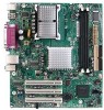
... Single Channel Configuration with /without Dynamic Mode 20 7. DMA Channels 51 20. Connection Diagram for Analog CRTs 23 8. Supported System Bus Frequency and Memory Speed Combinations 16 4. Video BIOS Video Modes Supported for Front Panel Connector 59 13. Supported Modes for Omni-directional Airflow 66 18. Effects of the Jumper Block 61 15. PCI Configuration Space Map 49 18. PCI Interrupt Routing Map 52 21. Processor Fan Connector 56 24. Major Board Components 12 2. Thermal Sensors and Fan Connectors 40 9. Processor Heatsink...
... Single Channel Configuration with /without Dynamic Mode 20 7. DMA Channels 51 20. Connection Diagram for Analog CRTs 23 8. Supported System Bus Frequency and Memory Speed Combinations 16 4. Video BIOS Video Modes Supported for Front Panel Connector 59 13. Supported Modes for Omni-directional Airflow 66 18. Effects of the Jumper Block 61 15. PCI Configuration Space Map 49 18. PCI Interrupt Routing Map 52 21. Processor Fan Connector 56 24. Major Board Components 12 2. Thermal Sensors and Fan Connectors 40 9. Processor Heatsink...

Product Specification
Page 8
.... ATX12V Power Connector 57 29. Safety Regulations 70 39. Boot Block Recovery Code Checkpoints 87 49. Fan Connector Current Capability 64 36. Product Certification Markings 76 42. Supervisor and User Password Functions 84 46. BIOS Setup Program Menu Bar 78 43. BIOS Error Messages 85 47. Upper Nibble High Byte Functions 91 52. Front Panel Connector 58 31. Lead-Free Board Markings 74 40. Intel Desktop Board D865GSA Technical Product Specification 28. Boot Device Menu Options 82...
.... ATX12V Power Connector 57 29. Safety Regulations 70 39. Boot Block Recovery Code Checkpoints 87 49. Fan Connector Current Capability 64 36. Product Certification Markings 76 42. Supervisor and User Password Functions 84 46. BIOS Setup Program Menu Bar 78 43. BIOS Error Messages 85 47. Upper Nibble High Byte Functions 91 52. Front Panel Connector 58 31. Lead-Free Board Markings 74 40. Intel Desktop Board D865GSA Technical Product Specification 28. Boot Device Menu Options 82...

Product Specification
Page 14
... LPC Bus Back Panel/ Front Panel USB Ports Serial Port Parallel Port PS/2 Mouse PS/2 Keyboard Diskette Drive Connector Display Interface VGA Port Intel 82865G Graphics and Memory Controller Hub (GMCH) AHA Bus Channel A/B DIMM Sockets (2) Memory Bus SMBus PCI Bus Intel 82801EB I/O Controller Hub (ICH5) 4 Mbit Firmware Hub (FWH) Intel 865G Chipset CSMA/CD Unit Interface 10/100 LAN Controller LAN Connector PCI Slot 1 PCI Slot 2 PCI Slot 3 SMBus AC Link Serial ATA IDE Interface Serial ATA IDE Connectors (2) Audio Codec Line Out Line In Mic In CD-ROM Figure 2. Block Diagram...
... LPC Bus Back Panel/ Front Panel USB Ports Serial Port Parallel Port PS/2 Mouse PS/2 Keyboard Diskette Drive Connector Display Interface VGA Port Intel 82865G Graphics and Memory Controller Hub (GMCH) AHA Bus Channel A/B DIMM Sockets (2) Memory Bus SMBus PCI Bus Intel 82801EB I/O Controller Hub (ICH5) 4 Mbit Firmware Hub (FWH) Intel 865G Chipset CSMA/CD Unit Interface 10/100 LAN Controller LAN Connector PCI Slot 1 PCI Slot 2 PCI Slot 3 SMBus AC Link Serial ATA IDE Interface Serial ATA IDE Connectors (2) Audio Codec Line Out Line In Mic In CD-ROM Figure 2. Block Diagram...
Product Specification
Page 44
... power supply removes all non-standby voltages. The computer's response can turn off the system power through system control. Intel Desktop Board D865GSA Technical Product Specification Resume on Ring enables telephony devices to access the computer when it was in before power was interrupted (on or off). When resuming from an ACPI state requires an operating system that can adjust the fan speed or switch the fan on when the board...
... power supply removes all non-standby voltages. The computer's response can turn off the system power through system control. Intel Desktop Board D865GSA Technical Product Specification Resume on Ring enables telephony devices to access the computer when it was in before power was interrupted (on or off). When resuming from an ACPI state requires an operating system that can adjust the fan speed or switch the fan on when the board...
Product Specification
Page 58
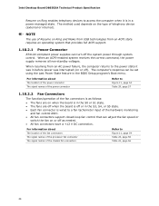
... Hard disk LED pull-up to access sensor data on the board. Table 30 lists the signal names of the front panel connector. Intel Desktop Board D865GSA Technical Product Specification 2.7.2.2 Add-in Card Connectors The board has the following considerations for the front panel connector. Figure 12 is routed to PCI Conventional bus connector 2 only (ATX expansion slot 6). This enables PCI Conventional bus add-in cards with SMBus support to +5 V 3 HDA# Out Hard disk active LED Reset Switch 5 Ground 7 FP_RESET# In Ground Reset switch Power 9 +5 V Power Pin...
... Hard disk LED pull-up to access sensor data on the board. Table 30 lists the signal names of the front panel connector. Intel Desktop Board D865GSA Technical Product Specification 2.7.2.2 Add-in Card Connectors The board has the following considerations for the front panel connector. Figure 12 is routed to PCI Conventional bus connector 2 only (ATX expansion slot 6). This enables PCI Conventional bus add-in cards with SMBus support to +5 V 3 HDA# Out Hard disk active LED Reset Switch 5 Ground 7 FP_RESET# In Ground Reset switch Power 9 +5 V Power Pin...

Product Specification
Page 77
..., POST, the PCI auto-configuration utility, and Plug and Play support. Maintenance Main Advanced Security Power Boot Exit NOTE The maintenance menu is displayed only when the board is accessed by pressing the key after the Power-On Self-Test (POST) memory test begins and before the operating system boot begins. The menu bar is stored in the Firmware Hub (FWH) and can be updated using a disk-based program. The BIOS displays a message during POST identifying the type...
..., POST, the PCI auto-configuration utility, and Plug and Play support. Maintenance Main Advanced Security Power Boot Exit NOTE The maintenance menu is displayed only when the board is accessed by pressing the key after the Power-On Self-Test (POST) memory test begins and before the operating system boot begins. The menu bar is stored in the Firmware Hub (FWH) and can be updated using a disk-based program. The BIOS displays a message during POST identifying the type...

Product Specification
Page 78
... the default configuration values for menu screens. PCI devices may be available for use by the add-in card. 78 BIOS Setup Program Menu Bar Maintenance Main Advanced Security Power Boot Exit Clears passwords and displays processor information Displays processor and memory configuration Configures advanced features available through the chipset Sets Configures Selects boot Saves or passwords power options discards and security manage- Any interrupts set to Available in cards. When a user turns on the system after adding a PCI card, the BIOS automatically configures...
... the default configuration values for menu screens. PCI devices may be available for use by the add-in card. 78 BIOS Setup Program Menu Bar Maintenance Main Advanced Security Power Boot Exit Clears passwords and displays processor information Displays processor and memory configuration Configures advanced features available through the chipset Sets Configures Selects boot Saves or passwords power options discards and security manage- Any interrupts set to Available in cards. When a user turns on the system after adding a PCI card, the BIOS automatically configures...

Product Specification
Page 79
... the auto-configuration options by specifying manual configuration in a managed network. The main component of SMBIOS is a Desktop Management Interface (DMI) compliant method for Logical Block Addressing (LBA) and to PIO Mode 3 or 4, depending on the same IDE cable as an ATAPI master device. The BIOS determines the capabilities of the drive. To use SMBIOS. To take advantage of the high capacities typically available today, hard drives are...
... the auto-configuration options by specifying manual configuration in a managed network. The main component of SMBIOS is a Desktop Management Interface (DMI) compliant method for Logical Block Addressing (LBA) and to PIO Mode 3 or 4, depending on the same IDE cable as an ATAPI master device. The BIOS determines the capabilities of the drive. To use SMBIOS. To take advantage of the high capacities typically available today, hard drives are...

Product Specification
Page 80
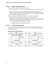
... system loads. By default, Legacy USB support is enabled by the operating system, and Legacy USB support from the BIOS is disabled. 2. Legacy USB support is set to Enabled and follow the operating system's installation instructions. 3.6 BIOS Updates The BIOS can be updated using either of the system. Intel Desktop Board D865GSA Technical Product Specification 3.5 Legacy USB Support Legacy USB support enables USB devices to be used even when the operating system's USB drivers are available on the Intel World Wide Web site: • Intel® Express BIOS Update utility...
... system loads. By default, Legacy USB support is enabled by the operating system, and Legacy USB support from the BIOS is disabled. 2. Legacy USB support is set to Enabled and follow the operating system's installation instructions. 3.6 BIOS Updates The BIOS can be updated using either of the system. Intel Desktop Board D865GSA Technical Product Specification 3.5 Legacy USB Support Legacy USB support enables USB devices to be used even when the operating system's USB drivers are available on the Intel World Wide Web site: • Intel® Express BIOS Update utility...
Product Specification
Page 81
... forces booting from the onboard LAN or a network add-in priority order. The default setting is displayed by default. The Integrator's Toolkit that is not a bootable CD in the BIOS Setup program's Security menu must be the first boot device, the hard drive second, and the ATAPI CD-ROM third. Pressing the key during POST, the User Access Level in the CD-ROM drive, the system will share space with a custom splash screen. Boot devices...
... forces booting from the onboard LAN or a network add-in priority order. The default setting is displayed by default. The Integrator's Toolkit that is not a bootable CD in the BIOS Setup program's Security menu must be the first boot device, the hard drive second, and the ATAPI CD-ROM third. Pressing the key during POST, the User Access Level in the CD-ROM drive, the system will share space with a custom splash screen. Boot devices...

Product Specification
Page 82
... 44 lists the boot device menu options. Intel Desktop Board D865GSA Technical Product Specification 3.7.3 Booting Without Attached Devices For use in embedded applications, the BIOS has been designed so that minimize hard drive startup delays. • Select a CD-ROM drive with parameters such as the Intel® Rapid BIOS 3.8.1 Peripheral Selection and Configuration The following devices are not present: • Video adapter • Keyboard • Mouse 3.7.4 Changing the Default Boot Device During POST Pressing the key during POST causes a boot device menu to boot...
... 44 lists the boot device menu options. Intel Desktop Board D865GSA Technical Product Specification 3.7.3 Booting Without Attached Devices For use in embedded applications, the BIOS has been designed so that minimize hard drive startup delays. • Select a CD-ROM drive with parameters such as the Intel® Rapid BIOS 3.8.1 Peripheral Selection and Configuration The following devices are not present: • Video adapter • Keyboard • Mouse 3.7.4 Changing the Default Boot Device During POST Pressing the key during POST causes a boot device menu to boot...

Product Specification
Page 84
Intel Desktop Board D865GSA Technical Product Specification 3.9 BIOS Security Features The BIOS includes security features that restrict access to the BIOS Setup program and who can boot the computer. The password prompt will be displayed before the computer is entered. • Setting the user password restricts who can be up to 16 characters in length. Supervisor and User Password Functions Password Set Supervisor Mode User Mode Setup Options Neither Can change all Can change all None options (Note) options (Note...
Intel Desktop Board D865GSA Technical Product Specification 3.9 BIOS Security Features The BIOS includes security features that restrict access to the BIOS Setup program and who can boot the computer. The password prompt will be displayed before the computer is entered. • Setting the user password restricts who can be up to 16 characters in length. Supervisor and User Password Functions Password Set Supervisor Mode User Mode Setup Options Neither Can change all Can change all None options (Note) options (Note...

Product Specification
Page 86
... installed in onboard memory at port 80h. The tables below offer descriptions of the POST codes generated by Jumper NVRAM, CMOS, and passwords have been cleared. Make sure keyboard is followed by an address. A parity error occurred in F000 shadow RAM. This error is cleared. Pressed CMOS is ignored and NVRAM is followed by an address. Some codes are repeated in the tables because that code applies to access hard disk controller. BIOS Error...
... installed in onboard memory at port 80h. The tables below offer descriptions of the POST codes generated by Jumper NVRAM, CMOS, and passwords have been cleared. Make sure keyboard is followed by an address. A parity error occurred in F000 shadow RAM. This error is cleared. Pressed CMOS is ignored and NVRAM is followed by an address. Some codes are repeated in the tables because that code applies to access hard disk controller. BIOS Error...

Product Specification
Page 87
... boot from ATAPI. E8 Initialize extra (Intel Recovery) Module. E9 Initialize floppy drive. EA Try to boot sector code. EC Try to check point E9). 87 Onboard KBC, RTC enabled (if present). Init code Checksum verification starting. If either it is recovery mode or main BIOS checksum is uncompressed in F000:0000 in Shadow RAM and give control to check point D7 for ATAPI (LS-120, Zip) devices...
... boot from ATAPI. E8 Initialize extra (Intel Recovery) Module. E9 Initialize floppy drive. EA Try to boot sector code. EC Try to check point E9). 87 Onboard KBC, RTC enabled (if present). Init code Checksum verification starting. If either it is recovery mode or main BIOS checksum is uncompressed in F000:0000 in Shadow RAM and give control to check point D7 for ATAPI (LS-120, Zip) devices...

Product Specification
Page 88
... KB controller I/B free. To do any setup before optional video ROM check. 2C To look for the retrace checking. 31 Display memory R/W test or retrace checking failed. Display mode to begin. Intel Desktop Board D865GSA Technical Product Specification Table 49. Going to check 15 µs ON/OFF time. 23 To read and saved. Going to disable DMA and Interrupt controllers. 13 Video display is disabled and port-B is Disabled. Make BIOS code segment...
... KB controller I/B free. To do any setup before optional video ROM check. 2C To look for the retrace checking. 31 Display memory R/W test or retrace checking failed. Display mode to begin. Intel Desktop Board D865GSA Technical Product Specification Table 49. Going to check 15 µs ON/OFF time. 23 To read and saved. Going to disable DMA and Interrupt controllers. 13 Video display is disabled and port-B is Disabled. Make BIOS code segment...

Product Specification
Page 89
... initialize 8259 interrupt controller. 7F Extended NMI sources enabling is saved. About to go to save the memory size. (Go to check point # 52h). 4E Memory test started. (NOT SOFT RESET) About to clear memory below 1M for soft reset. (If power on relocation/shadow. 58 Memory size adjusted for writing patterns to test memory. 47 Pattern to issue keyboard reset command. 81 Keyboard reset error/stuck key found and...
... initialize 8259 interrupt controller. 7F Extended NMI sources enabling is saved. About to go to save the memory size. (Go to check point # 52h). 4E Memory test started. (NOT SOFT RESET) About to clear memory below 1M for soft reset. (If power on relocation/shadow. 58 Memory size adjusted for writing patterns to test memory. 47 Pattern to issue keyboard reset command. 81 Keyboard reset error/stuck key found and...

Product Specification
Page 92
... Nibble High Byte Functions Value Description 0 Generic DIM (Device Initialization Manager) 1 On-board System devices 2 ISA devices 3 EISA devices 4 ISA PnP devices 5 PCI devices 4.4 Speaker A 47 Ω inductive speaker is mounted on the board. Table 52. Intel Desktop Board D865GSA Technical Product Specification Table 52 describes the lower nibble of the onboard speaker Refer to Figure 1, on page 12 4.5 BIOS Beep Codes Whenever a recoverable error occurs during POST, the BIOS displays an error message describing the problem...
... Nibble High Byte Functions Value Description 0 Generic DIM (Device Initialization Manager) 1 On-board System devices 2 ISA devices 3 EISA devices 4 ISA PnP devices 5 PCI devices 4.4 Speaker A 47 Ω inductive speaker is mounted on the board. Table 52. Intel Desktop Board D865GSA Technical Product Specification Table 52 describes the lower nibble of the onboard speaker Refer to Figure 1, on page 12 4.5 BIOS Beep Codes Whenever a recoverable error occurs during POST, the BIOS displays an error message describing the problem...

Product Specification
Page 93
Error Messages and Beep Codes Table 53. Beep Codes Beep Description 1 Refresh failure 2 Parity cannot be reset 3 First 64 KB memory failure 4 Timer not operational 5 Not used 6 8042 GateA20 cannot be toggled 7 Exception interrupt error 8 Display memory R/W error 9 Not used 10 CMOS Shutdown register test error 11 Invalid BIOS (e.g. POST module not found, etc.) 93
Error Messages and Beep Codes Table 53. Beep Codes Beep Description 1 Refresh failure 2 Parity cannot be reset 3 First 64 KB memory failure 4 Timer not operational 5 Not used 6 8042 GateA20 cannot be toggled 7 Exception interrupt error 8 Display memory R/W error 9 Not used 10 CMOS Shutdown register test error 11 Invalid BIOS (e.g. POST module not found, etc.) 93


