
Product Specification
Page 7
...108 4.4.8 USB Configuration Submenu 109 4.4.9 Chipset Configuration Submenu 110 4.4.10 Fan Control Configuration Submenu 112 4.4.11 Hardware Monitoring 113 4.5 Security Menu ...114 4.6 Power Menu ...115 4.6.1 ACPI Submenu 115 4.7 Boot Menu ...116 4.7.1 Boot Device Priority Submenu 117 4.7.2 Hard Disk Drives Submenu 118 4.7.3 Removable Devices Submenu 118 4.7.4 ATAPI CD-ROM Drives Submenu 119 4.8 Exit Menu ...119 5 Error Messages and Beep Codes 5.1 BIOS Error Messages 121 5.2 Port 80h POST Codes 123 5.3 Bus Initialization Checkpoints 127 5.4 Speaker ...128 5.5 BIOS Beep Codes ...128...
...108 4.4.8 USB Configuration Submenu 109 4.4.9 Chipset Configuration Submenu 110 4.4.10 Fan Control Configuration Submenu 112 4.4.11 Hardware Monitoring 113 4.5 Security Menu ...114 4.6 Power Menu ...115 4.6.1 ACPI Submenu 115 4.7 Boot Menu ...116 4.7.1 Boot Device Priority Submenu 117 4.7.2 Hard Disk Drives Submenu 118 4.7.3 Removable Devices Submenu 118 4.7.4 ATAPI CD-ROM Drives Submenu 119 4.8 Exit Menu ...119 5 Error Messages and Beep Codes 5.1 BIOS Error Messages 121 5.2 Port 80h POST Codes 123 5.3 Bus Initialization Checkpoints 127 5.4 Speaker ...128 5.5 BIOS Beep Codes ...128...

Product Specification
Page 8
...Single Channel Configuration without Dynamic Mode 26 7. LAN Connector LED Locations 38 15. Location of the Jumper Blocks 72 27. Back Panel Connectors 58 19. Power and Hardware Control Connectors 62 21. External I /O Shield Dimensions 76 30. Localized High Temperature Zones 79 Tables 1. Manufacturing Options 13 4. System Memory Map 51 viii Intel Desktop Board D865PERC/D865PESO Technical Product Specification Figures 1. Back Panel Audio Connector Options for Front Panel Connector 69 25. Thermal Monitoring...40 16. Audio Connectors ...60 20. Connection Diagram...
...Single Channel Configuration without Dynamic Mode 26 7. LAN Connector LED Locations 38 15. Location of the Jumper Blocks 72 27. Back Panel Connectors 58 19. Power and Hardware Control Connectors 62 21. External I /O Shield Dimensions 76 30. Localized High Temperature Zones 79 Tables 1. Manufacturing Options 13 4. System Memory Map 51 viii Intel Desktop Board D865PERC/D865PESO Technical Product Specification Figures 1. Back Panel Audio Connector Options for Front Panel Connector 69 25. Thermal Monitoring...40 16. Audio Connectors ...60 20. Connection Diagram...
Product Specification
Page 9
...50. Advanced Menu...96 52. PCI Configuration Submenu 97 53. Fan Control Configuration Submenu 112 ix PCI Interrupt Routing Map 56 20. Processor Fan Connector 63 26. BIOS Setup Configuration Jumper Settings 73 37. DC Loading Characteristics 77 38. Drive Configuration Submenu 102 56. Event Log Configuration Submenu 107 59. Rear Chassis Fan Connector 62 24. Auxiliary Front Panel Power/Sleep/Message-Waiting LED Connector 69 32. Front Panel Audio Connector/Jumper Block 73 36. Desktop Board D865PERC/D865PESO Environmental Specifications 81 42. Boot...
...50. Advanced Menu...96 52. PCI Configuration Submenu 97 53. Fan Control Configuration Submenu 112 ix PCI Interrupt Routing Map 56 20. Processor Fan Connector 63 26. BIOS Setup Configuration Jumper Settings 73 37. DC Loading Characteristics 77 38. Drive Configuration Submenu 102 56. Event Log Configuration Submenu 107 59. Rear Chassis Fan Connector 62 24. Auxiliary Front Panel Power/Sleep/Message-Waiting LED Connector 69 32. Front Panel Audio Connector/Jumper Block 73 36. Desktop Board D865PERC/D865PESO Environmental Specifications 81 42. Boot...

Product Specification
Page 13
... values • Three fan connectors • Three fan sense inputs used to monitor fan activity • Fan speed control For information about Available configurations for PCI Local Bus Specification Revision 2.2 • Suspend to RAM support • Wake on PCI, RS-232, front panel, PS/2 devices, and USB ports Expansion Capabilities • D865PERC: Six PCI bus add-in card connectors (SMBus routed to Section 1.3, page 17 13 Manufacturing Options SCSI Hard Drive Activity LED Connector Allows add-in hard drive controller (SCSI or other...
... values • Three fan connectors • Three fan sense inputs used to monitor fan activity • Fan speed control For information about Available configurations for PCI Local Bus Specification Revision 2.2 • Suspend to RAM support • Wake on PCI, RS-232, front panel, PS/2 devices, and USB ports Expansion Capabilities • D865PERC: Six PCI bus add-in card connectors (SMBus routed to Section 1.3, page 17 13 Manufacturing Options SCSI Hard Drive Activity LED Connector Allows add-in hard drive controller (SCSI or other...

Product Specification
Page 31
... 18 1.8.3 IDE Support The board provides four IDE interface connectors: • Two Parallel ATA IDE connectors, which support a total of four devices (two per connector 1.8.3.1 Parallel ATE IDE Interfaces The ICH5's Parallel ATA IDE controller has two independent bus-mastering Parallel ATA IDE interfaces that can be configured as CD-ROM drives) and ATA devices using the transfer modes listed in Section 4.4.4.1 on page 104. hard disk drive) For information about The location of the USB connectors on...
... 18 1.8.3 IDE Support The board provides four IDE interface connectors: • Two Parallel ATA IDE connectors, which support a total of four devices (two per connector 1.8.3.1 Parallel ATE IDE Interfaces The ICH5's Parallel ATA IDE controller has two independent bus-mastering Parallel ATA IDE interfaces that can be configured as CD-ROM drives) and ATA devices using the transfer modes listed in Section 4.4.4.1 on page 104. hard disk drive) For information about The location of the USB connectors on...

Product Specification
Page 32
... battery (CR2032) powers the real-time clock and CMOS memory. In legacy mode, standard IDE I /O controller provides the following features: 32 A point-to the operating system. When the computer is transparent to -point interface is a 1 x 2-pin connector that allows an add-in hard drive controller or the onboard IDE controller (Parallel ATA or Serial ATA). Intel Desktop Board D865PERC/D865PESO Technical Product Specification 1.8.3.2 Serial ATA Interfaces The ICH5's Serial ATA controller offers two independent Serial ATA ports...
... battery (CR2032) powers the real-time clock and CMOS memory. In legacy mode, standard IDE I /O controller provides the following features: 32 A point-to the operating system. When the computer is transparent to -point interface is a 1 x 2-pin connector that allows an add-in hard drive controller or the onboard IDE controller (Parallel ATA or Serial ATA). Intel Desktop Board D865PERC/D865PESO Technical Product Specification 1.8.3.2 Serial ATA Interfaces The ICH5's Serial ATA controller offers two independent Serial ATA ports...

Product Specification
Page 57
... audio) Fans [three] Power Add-in boards (PCI and AGP) Parallel ATA IDE Diskette drive SCSI hard drive activity LED (optional) Chassis intrusion Serial ATA • External I/O connectors (see page 68) Front panel USB (two connector for four ports) Auxiliary front panel power/sleep/message-waiting LED Front panel (power/sleep/message-waiting LED, power switch, hard drive activity LED, reset switch, and auxiliary front panel power LED) ✏ NOTE When installing the D865PESO board in the load...
... audio) Fans [three] Power Add-in boards (PCI and AGP) Parallel ATA IDE Diskette drive SCSI hard drive activity LED (optional) Chassis intrusion Serial ATA • External I/O connectors (see page 68) Front panel USB (two connector for four ports) Auxiliary front panel power/sleep/message-waiting LED Front panel (power/sleep/message-waiting LED, power switch, hard drive activity LED, reset switch, and auxiliary front panel power LED) ✏ NOTE When installing the D865PESO board in the load...

Product Specification
Page 65
... IDE [white] SCSI hard drive activity LED (optional) Serial ATA connector 1 Serial ATA connector 0 Figure 21. Note the following considerations for the PCI bus connectors (for the Desktop Board D865PERC. This enables PCI bus add-in Board and Peripheral Interface Connectors 65 D865PERC Add-in boards with SMBus support to access sensor data on the Desktop Board. Technical Reference 2.8.2.4 Add-in Board and Peripheral Interface Connectors Figure 21 shows the location of the add-in board connector and peripheral connectors...
... IDE [white] SCSI hard drive activity LED (optional) Serial ATA connector 1 Serial ATA connector 0 Figure 21. Note the following considerations for the PCI bus connectors (for the Desktop Board D865PERC. This enables PCI bus add-in Board and Peripheral Interface Connectors 65 D865PERC Add-in boards with SMBus support to access sensor data on the Desktop Board. Technical Reference 2.8.2.4 Add-in Board and Peripheral Interface Connectors Figure 21 shows the location of the add-in board connector and peripheral connectors...
Product Specification
Page 86
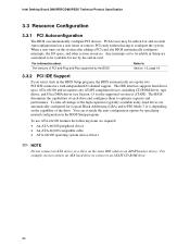
... system. To use by specifying manual configuration in the BIOS Setup program. Intel Desktop Board D865PERC/D865PESO Technical Product Specification 3.3 Resource Configuration 3.3.1 PCI Autoconfiguration The BIOS can override the auto-configuration options by the add-in card. Autoconfiguration lets a user insert or remove PCI cards without having to optimize capacity and performance. When a user turns on the capability of the high capacities typically available today, hard drives are considered to Section 1.5, page 18 3.3.2 PCI IDE Support If you...
... system. To use by specifying manual configuration in the BIOS Setup program. Intel Desktop Board D865PERC/D865PESO Technical Product Specification 3.3 Resource Configuration 3.3.1 PCI Autoconfiguration The BIOS can override the auto-configuration options by the add-in card. Autoconfiguration lets a user insert or remove PCI cards without having to optimize capacity and performance. When a user turns on the capability of the high capacities typically available today, hard drives are considered to Section 1.5, page 18 3.3.2 PCI IDE Support If you...

Product Specification
Page 93
.... BIOS Setup Program Menu Bar Maintenance Main Advanced Security Clears passwords and displays processor information Displays processor and memory configuration Configures advanced features available through the chipset Sets passwords and security features Power Boot Configures power management features and power supply controls Selects boot options Exit Saves or discards changes to view and change the BIOS settings for the computer. Section 2.9.2 on page 73 tells how to put the Desktop Board in configure mode. The BIOS Setup program is accessed by pressing the key after...
.... BIOS Setup Program Menu Bar Maintenance Main Advanced Security Clears passwords and displays processor information Displays processor and memory configuration Configures advanced features available through the chipset Sets passwords and security features Power Boot Configures power management features and power supply controls Selects boot options Exit Saves or discards changes to view and change the BIOS settings for the computer. Section 2.9.2 on page 73 tells how to put the Desktop Board in configure mode. The BIOS Setup program is accessed by pressing the key after...

Product Specification
Page 94
... Load the default configuration values for configure mode setting information. Intel Desktop Board D865PERC/D865PESO Technical Product Specification Table 48 lists the function keys available for clearing Setup passwords and displaying processor information. Maintenance Menu Feature Options Clear All Passwords • Ok (default) • Cancel CPU Stepping Signature No options CPU Microcode Update Revision No options Description Clears the user and supervisor passwords. Maintenance Main Advanced Security Power Boot Exit The menu shown in configure mode. Displays CPU...
... Load the default configuration values for configure mode setting information. Intel Desktop Board D865PERC/D865PESO Technical Product Specification Table 48 lists the function keys available for clearing Setup passwords and displaying processor information. Maintenance Menu Feature Options Clear All Passwords • Ok (default) • Cancel CPU Stepping Signature No options CPU Microcode Update Revision No options Description Clears the user and supervisor passwords. Maintenance Main Advanced Security Power Boot Exit The menu shown in configure mode. Displays CPU...
Product Specification
Page 101
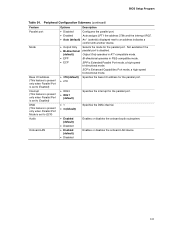
.... Peripheral Configuration Submenu (continued) Feature Parallel port Mode Base I /O address for the parallel port. • 278 • IRQ 5 • IRQ 7 (default) • 1 • 3 (default) Specifies the interrupt for the parallel port. Enables or disables the onboard LAN device. 101 ECP is Extended Parallel Port mode, a high-speed bi-directional mode. BIOS Setup Program Table 54. Not available if the • Bi-directional parallel port is disabled. (default) Output Only operates in AT*-compatible mode...
.... Peripheral Configuration Submenu (continued) Feature Parallel port Mode Base I /O address for the parallel port. • 278 • IRQ 5 • IRQ 7 (default) • 1 • 3 (default) Specifies the interrupt for the parallel port. Enables or disables the onboard LAN device. 101 ECP is Extended Parallel Port mode, a high-speed bi-directional mode. BIOS Setup Program Table 54. Not available if the • Bi-directional parallel port is disabled. (default) Output Only operates in AT*-compatible mode...
Product Specification
Page 105
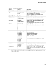
... the IDE configuration mode for the drive. User allows capabilities to be set to User.) Displays the type of drive installed. Auto fills-in the above table. SATA/PATA Submenus Feature Drive Installed Type Maximum Capacity LBA/Large Mode Block Mode PIO Mode DMA Mode S.M.A.R.T. Displays the drive capacity. The BIOS will be displayed in capabilities from ATA/ATAPI device. Displays whether automatic translation mode is enabled for the hard disk. (This item is read-only unless Type is set to User.) Displays whether...
... the IDE configuration mode for the drive. User allows capabilities to be set to User.) Displays the type of drive installed. Auto fills-in the above table. SATA/PATA Submenus Feature Drive Installed Type Maximum Capacity LBA/Large Mode Block Mode PIO Mode DMA Mode S.M.A.R.T. Displays the drive capacity. The BIOS will be displayed in capabilities from ATA/ATAPI device. Displays whether automatic translation mode is enabled for the hard disk. (This item is read-only unless Type is set to User.) Displays whether...

Product Specification
Page 106
... To access this menu, select Advanced on the menu bar and then Floppy Configuration. Maintenance Main Advanced Security Power PCI Configuration Boot Configuration Peripheral Configuration Drive Configuration Floppy Configuration Event Log Configuration Video Configuration USB Configuration Chipset Configuration Fan Control Configuration Hardware Monitoring Boot Exit The submenu represented by Table 57 is used for the diskette drive. 106 Floppy Configuration Submenu Feature Diskette Controller Floppy A Diskette Write Protect Options • Disabled • Enabled (default...
... To access this menu, select Advanced on the menu bar and then Floppy Configuration. Maintenance Main Advanced Security Power PCI Configuration Boot Configuration Peripheral Configuration Drive Configuration Floppy Configuration Event Log Configuration Video Configuration USB Configuration Chipset Configuration Fan Control Configuration Hardware Monitoring Boot Exit The submenu represented by Table 57 is used for the diskette drive. 106 Floppy Configuration Submenu Feature Diskette Controller Floppy A Diskette Write Protect Options • Disabled • Enabled (default...

Product Specification
Page 111
... two consecutive common clocks. Enabled allows the DRAM controller to the memory detected. Selects the number of detected SDRAM settings. This option is displayed only if the installed processor has an 800 MHz system bus. 4. This option is displayed only if the installed processor has a 533 MHz system bus. 3. Manual - Notes: 1. Corresponds to CAS# Delay (Note 4) SDRAM RAS# Precharge (Note 4) Options • Auto (default) • Enabled • Disabled • Auto (default) • Manual - Selects the...
... two consecutive common clocks. Enabled allows the DRAM controller to the memory detected. Selects the number of detected SDRAM settings. This option is displayed only if the installed processor has an 800 MHz system bus. 4. This option is displayed only if the installed processor has a 533 MHz system bus. 3. Manual - Notes: 1. Corresponds to CAS# Delay (Note 4) SDRAM RAS# Precharge (Note 4) Options • Auto (default) • Enabled • Disabled • Auto (default) • Manual - Selects the...
Product Specification
Page 112
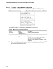
... Product Specification 4.4.10 Fan Control Configuration Submenu To access this menu, select Advanced on . 112 Maintenance Main Advanced Security Power PCI Configuration Boot Configuration Peripheral Configuration Drive Configuration Floppy Configuration Event Log Configuration Video Configuration USB Configuration Chipset Configuration Fan Control Configuration Hardware Monitoring Boot Exit The submenu represented in Table 62 is for configuring fan control options. Fan Control Configuration Submenu Feature Fan Control Lowest Fan Speed Options • Disabled • Enabled (default...
... Product Specification 4.4.10 Fan Control Configuration Submenu To access this menu, select Advanced on . 112 Maintenance Main Advanced Security Power PCI Configuration Boot Configuration Peripheral Configuration Drive Configuration Floppy Configuration Event Log Configuration Video Configuration USB Configuration Chipset Configuration Fan Control Configuration Hardware Monitoring Boot Exit The submenu represented in Table 62 is for configuring fan control options. Fan Control Configuration Submenu Feature Fan Control Lowest Fan Speed Options • Disabled • Enabled (default...

Product Specification
Page 114
... (default) Password can be up to the BIOS Setup Utility. No Access prevents user access to view but not change the BIOS Setup Utility fields. View Only allows the user to the BIOS Setup Utility. User must enter BIOS setup Security Menu and select "Clear Chassis Intrusion Status" to continue. Log, notify til cleared = Halts system during POST. Table 64. Security Menu If no password entered previously: Feature Supervisor Password Options No options Description Reports if there is a user password set . 3. Maintenance Main Advanced Security Power Boot...
... (default) Password can be up to the BIOS Setup Utility. No Access prevents user access to view but not change the BIOS Setup Utility fields. View Only allows the user to the BIOS Setup Utility. User must enter BIOS setup Security Menu and select "Clear Chassis Intrusion Status" to continue. Log, notify til cleared = Halts system during POST. Table 64. Security Menu If no password entered previously: Feature Supervisor Password Options No options Description Reports if there is a user password set . 3. Maintenance Main Advanced Security Power Boot...
Product Specification
Page 116
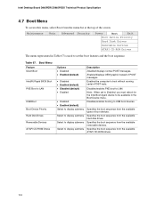
... Boot Device Priority Hard Disk Drives Removable Devices ATAPI CD-ROM Drives The menu represented in Table 67 is used to set to Enabled, you must reboot for the Intel Boot Agent device to be available in the Boot Device menu. Disables/enables booting to LAN. Specifies the boot sequence from the available types of boot devices. Enabled displays OEM graphic instead of the screen. Specifies the boot sequence from the menu bar at the top of POST messages. Intel Desktop Board D865PERC/D865PESO Technical Product Specification 4.7 Boot Menu To access...
... Boot Device Priority Hard Disk Drives Removable Devices ATAPI CD-ROM Drives The menu represented in Table 67 is used to set to Enabled, you must reboot for the Intel Boot Agent device to be available in the Boot Device menu. Disables/enables booting to LAN. Specifies the boot sequence from the available types of boot devices. Enabled displays OEM graphic instead of the screen. Specifies the boot sequence from the menu bar at the top of POST messages. Intel Desktop Board D865PERC/D865PESO Technical Product Specification 4.7 Boot Menu To access...
Product Specification
Page 123
... PCI bus connector 1. Init code to be copied to segment 0 and control to be installed in F000 Shadow RAM. Uncompress the main BIOS module. Compressed recovery code is uncompressed in F000:0000 in the tables because that code applies to boot sector code. Try to I/O port 80h. Booting from floppy failed, look for giving control to boot sector code. Booting from ATAPI. Initialize extra (Intel Recovery) Module. Do necessary chipset initialization, start memory refresh, and do memory sizing. Control...
... PCI bus connector 1. Init code to be copied to segment 0 and control to be installed in F000 Shadow RAM. Uncompress the main BIOS module. Compressed recovery code is uncompressed in F000:0000 in the tables because that code applies to boot sector code. Try to I/O port 80h. Booting from floppy failed, look for giving control to boot sector code. Booting from ATAPI. Initialize extra (Intel Recovery) Module. Do necessary chipset initialization, start memory refresh, and do memory sizing. Control...

Product Specification
Page 128
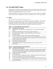
... during POST, the BIOS displays an error message describing the problem (see Table 80). For information about The location of the onboard speaker on the Desktop Board D865PERC The location of the onboard speaker on the Desktop Board D865PESO Refer to zero. Before shutting down the system if they fail. The speaker provides audible error code (beep code) information during POST if the video configuration fails (a faulty video card or no card installed) or if an external ROM...
... during POST, the BIOS displays an error message describing the problem (see Table 80). For information about The location of the onboard speaker on the Desktop Board D865PERC The location of the onboard speaker on the Desktop Board D865PESO Refer to zero. Before shutting down the system if they fail. The speaker provides audible error code (beep code) information during POST if the video configuration fails (a faulty video card or no card installed) or if an external ROM...


