
Product Guide
Page 3
... product features 2 Installing and Replacing Desktop Board Components: instructions on how to update the BIOS A Error Messages and Indicators: information about BIOS error messages and beep codes B Regulatory Compliance: describes the board's adherence to install the Desktop Board and other environments, such as Information Technology Equipment (I.T.E.) for use in this Product Guide are arranged as follows: 1 Desktop Board Features: a summary of data. Use Only for Intended Applications All Intel Desktop Boards are used in personal computers...
... product features 2 Installing and Replacing Desktop Board Components: instructions on how to update the BIOS A Error Messages and Indicators: information about BIOS error messages and beep codes B Regulatory Compliance: describes the board's adherence to install the Desktop Board and other environments, such as Information Technology Equipment (I.T.E.) for use in this Product Guide are arranged as follows: 1 Desktop Board Features: a summary of data. Use Only for Intended Applications All Intel Desktop Boards are used in personal computers...
Product Guide
Page 5
...15 Main Memory...15 Graphics Subsystem 15 Integrated Graphics 15 Intel® HD Graphics 16 High-Definition Multimedia Interface* (HDMI 16 Digital Visual Interface (DVI-I 16 VGA Displays 16 PCI Express* x16 Graphics 17 Audio Subsystem 17 LAN Subsystem 18 USB Support ...19 SATA Support...19 Expandability...19 Legacy I/O ...20 BIOS ...20 SATA Auto Configuration 20 PCI*/PCI Express Auto Configuration 20 Security Passwords 21 Hardware Management 21 Hardware Monitoring and Fan Speed Control 21 Fan Monitoring 21 Chassis Intrusion 22 Power Management 22 Software Support 22 ACPI 22...
...15 Main Memory...15 Graphics Subsystem 15 Integrated Graphics 15 Intel® HD Graphics 16 High-Definition Multimedia Interface* (HDMI 16 Digital Visual Interface (DVI-I 16 VGA Displays 16 PCI Express* x16 Graphics 17 Audio Subsystem 17 LAN Subsystem 18 USB Support ...19 SATA Support...19 Expandability...19 Legacy I/O ...20 BIOS ...20 SATA Auto Configuration 20 PCI*/PCI Express Auto Configuration 20 Security Passwords 21 Hardware Management 21 Hardware Monitoring and Fan Speed Control 21 Fan Monitoring 21 Chassis Intrusion 22 Power Management 22 Software Support 22 ACPI 22...

Product Guide
Page 6
... a PCI Express x16 Graphics Card 42 Connecting SATA Drives 43 Connecting to the Internal Headers 44 Front Panel Audio Header 45 Chassis Intrusion Header 45 Consumer IR (CIR) Headers 46 Alternate Front Panel Power LED Header 47 Front Panel Header 47 Front Panel USB 2.0 Headers 48 S/PDIF Header 48 Connecting to the Audio System 49 Connecting Chassis Fan and Power Supply Cables 50 Connecting a Chassis Fan 50 Connecting Power Supply Cables 51 Setting the BIOS Configuration Jumper 52 Clearing Passwords 53 Replacing the Battery 54 3 Updating the BIOS Updating the BIOS with the Intel...
... a PCI Express x16 Graphics Card 42 Connecting SATA Drives 43 Connecting to the Internal Headers 44 Front Panel Audio Header 45 Chassis Intrusion Header 45 Consumer IR (CIR) Headers 46 Alternate Front Panel Power LED Header 47 Front Panel Header 47 Front Panel USB 2.0 Headers 48 S/PDIF Header 48 Connecting to the Audio System 49 Connecting Chassis Fan and Power Supply Cables 50 Connecting a Chassis Fan 50 Connecting Power Supply Cables 51 Setting the BIOS Configuration Jumper 52 Clearing Passwords 53 Replacing the Battery 54 3 Updating the BIOS Updating the BIOS with the Intel...

Product Guide
Page 7
...Battery 59 26. Intel Desktop Board DH67BL Components 12 2. Intel Desktop Board DH67BL Mounting Screw Hole Locations 30 6. Intel Desktop Board DH67BL China RoHS Material Self Declaration Table 72 vii Back Panel Audio Connectors 49 22. Connecting Power Supply Cables 51 24. Lift the Load Plate 32 8. Connecting the Processor Fan Heat Sink Power Cable to the Processor Fan Header.35 12. Removing a PCI Express x16 Graphics Card 42 19. LAN Connector LEDs 18 3. Connecting a SATA Drive 43 20. Installing the I/O Shield 29 5. Example Dual Channel Memory Configuration...
...Battery 59 26. Intel Desktop Board DH67BL Components 12 2. Intel Desktop Board DH67BL Mounting Screw Hole Locations 30 6. Intel Desktop Board DH67BL China RoHS Material Self Declaration Table 72 vii Back Panel Audio Connectors 49 22. Connecting Power Supply Cables 51 24. Lift the Load Plate 32 8. Connecting the Processor Fan Heat Sink Power Cable to the Processor Fan Header.35 12. Removing a PCI Express x16 Graphics Card 42 19. LAN Connector LEDs 18 3. Connecting a SATA Drive 43 20. Installing the I/O Shield 29 5. Example Dual Channel Memory Configuration...

Product Guide
Page 10
... LAN controller including an RJ-45 back panel connector with integrated status LEDs • Intel® BIOS resident in an SPI Flash device • Support for Advanced Configuration and Power Interface (ACPI), Plug and Play, and SMBIOS • BIOS support for Hyper Boot • UEFI to support hard disk drives larger than 2 TB Instantly Available PC Technology • Support for PCI Local Bus Specification Revision 2.3 • Support for PCI Express Base Specification Revision 2.0 • Suspend to RAM support • Wake on PCI Express, LAN, front panel, CIR, and USB ports...
... LAN controller including an RJ-45 back panel connector with integrated status LEDs • Intel® BIOS resident in an SPI Flash device • Support for Advanced Configuration and Power Interface (ACPI), Plug and Play, and SMBIOS • BIOS support for Hyper Boot • UEFI to support hard disk drives larger than 2 TB Instantly Available PC Technology • Support for PCI Local Bus Specification Revision 2.3 • Support for PCI Express Base Specification Revision 2.0 • Suspend to RAM support • Wake on PCI Express, LAN, front panel, CIR, and USB ports...

Product Guide
Page 20
...) support • Serial IRQ interface compatible with serialized IRQ support for PCI Conventional bus systems • Intelligent power management, including a programmable wake-up event interface The BIOS Setup program provides configuration options for your computer, the autoconfiguration utility in card. 20 The BIOS can override the auto-configuration options by default. You do not need to run the BIOS Setup program after you install a SATA device (such as a hard drive) in your computer. Intel Desktop Board DH67BL Product Guide Legacy I/O The board's Legacy I/O Controller...
...) support • Serial IRQ interface compatible with serialized IRQ support for PCI Conventional bus systems • Intelligent power management, including a programmable wake-up event interface The BIOS Setup program provides configuration options for your computer, the autoconfiguration utility in card. 20 The BIOS can override the auto-configuration options by default. You do not need to run the BIOS Setup program after you install a SATA device (such as a hard drive) in your computer. Intel Desktop Board DH67BL Product Guide Legacy I/O The board's Legacy I/O Controller...
Product Guide
Page 22
...'s Boot menu. See Figure 1 for the location of a computer. Hardware Support Power Connectors ATX12V-compliant power supplies can be set by using the Last Power State feature in before power was interrupted (either on the chassis that can turn off ). When resuming from CIR Software Support ACPI ACPI gives the operating system direct control over the power management and Plug and Play functions of the power connectors. 22 See Figure 23 on the Desktop Board. Intel Desktop Board DH67BL...
...'s Boot menu. See Figure 1 for the location of a computer. Hardware Support Power Connectors ATX12V-compliant power supplies can be set by using the Last Power State feature in before power was interrupted (either on the chassis that can turn off ). When resuming from CIR Software Support ACPI ACPI gives the operating system direct control over the power management and Plug and Play functions of the power connectors. 22 See Figure 23 on the Desktop Board. Intel Desktop Board DH67BL...
Product Guide
Page 25
... board's beep codes. When the computer is mounted on a PCI Express bus add-in card is asserted, the computer wakes from an ACPI S1 or S3 state. The clock is plugged in CMOS RAM (for a description of the battery. NOTE If the battery and AC power fail, date and time values will be reset and the user will be accurate. When the battery voltage drops below a certain level, the BIOS Setup program settings...
... board's beep codes. When the computer is mounted on a PCI Express bus add-in card is asserted, the computer wakes from an ACPI S1 or S3 state. The clock is plugged in CMOS RAM (for a description of the battery. NOTE If the battery and AC power fail, date and time values will be reset and the user will be accurate. When the battery voltage drops below a certain level, the BIOS Setup program settings...

Product Guide
Page 27
... Desktop Board Components This chapter tells you how to: • Install the I/O shield • Install and remove the Desktop Board • Install and remove a processor • Install and remove memory • Install and remove a PCI Express x16 card • Connect SATA drives • Connect to the internal headers • Connect to the audio system • Connect chassis fan and power supply cables • Set the BIOS configuration jumper • Clear passwords • Replace the battery Before You Begin CAUTION The procedures in this chapter only at an ESD workstation using...
... Desktop Board Components This chapter tells you how to: • Install the I/O shield • Install and remove the Desktop Board • Install and remove a processor • Install and remove memory • Install and remove a PCI Express x16 card • Connect SATA drives • Connect to the internal headers • Connect to the audio system • Connect chassis fan and power supply cables • Set the BIOS configuration jumper • Clear passwords • Replace the battery Before You Begin CAUTION The procedures in this chapter only at an ESD workstation using...

Product Guide
Page 53
Installing and Replacing Desktop Board Components The three-pin BIOS jumper block enables board configuration to normal mode. 1. Table 14. Turn off all peripheral devices connected to clear passwords. Jumper Settings for the BIOS Setup Program Modes Jumper Setting Mode Normal (default) (1-2) Description The BIOS uses the current configuration and passwords for the BIOS Setup program modes. Disconnect the computer's power cord from the AC power source (wall outlet or power adapter). 3. Clearing Passwords This procedure assumes that the board is installed in the computer and the...
Installing and Replacing Desktop Board Components The three-pin BIOS jumper block enables board configuration to normal mode. 1. Table 14. Turn off all peripheral devices connected to clear passwords. Jumper Settings for the BIOS Setup Program Modes Jumper Setting Mode Normal (default) (1-2) Description The BIOS uses the current configuration and passwords for the BIOS Setup program modes. Disconnect the computer's power cord from the AC power source (wall outlet or power adapter). 3. Clearing Passwords This procedure assumes that the board is installed in the computer and the...
Product Guide
Page 61
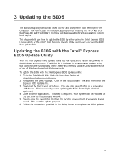
... last Express BIOS Update window. 5. Follow the instructions provided in the Windows environment. Click on your hard drive. (You can access the BIOS Setup program by either using the Intel Express BIOS Update utility or the Intel® Flash Memory Update Utility, and how to the DH67BL page. Go to view and change the BIOS settings for multiple identical systems.) 4. This chapter tells you can update the system BIOS while in the dialog boxes to a removable USB device. The BIOS file is useful if...
... last Express BIOS Update window. 5. Follow the instructions provided in the Windows environment. Click on your hard drive. (You can access the BIOS Setup program by either using the Intel Express BIOS Update utility or the Intel® Flash Memory Update Utility, and how to the DH67BL page. Go to view and change the BIOS settings for multiple identical systems.) 4. This chapter tells you can update the system BIOS while in the dialog boxes to a removable USB device. The BIOS file is useful if...

Product Specification
Page 8
...3.5 Legacy USB Support 65 3.6 BIOS Updates 66 3.6.1 Language Support 66 3.6.2 Custom Splash Screen 67 3.7 BIOS Recovery 67 3.8 Boot Options 68 3.8.1 Optical Drive Boot 68 3.8.2 Network Boot 68 3.8.3 Booting Without Attached Devices 68 3.8.4 Changing the Default Boot Device During POST 68 3.9 Adjusting Boot Speed 69 3.9.1 Peripheral Selection and Configuration 69 3.9.2 BIOS Boot Optimizations 69 3.10 BIOS Security Features 70 3.11 BIOS Performance Features 71 4 Error Messages and Beep Codes 4.1 Speaker 73 4.2 BIOS Beep Codes 73 4.3 Front-panel Power LED Blink Codes 74 4.4 BIOS...
...3.5 Legacy USB Support 65 3.6 BIOS Updates 66 3.6.1 Language Support 66 3.6.2 Custom Splash Screen 67 3.7 BIOS Recovery 67 3.8 Boot Options 68 3.8.1 Optical Drive Boot 68 3.8.2 Network Boot 68 3.8.3 Booting Without Attached Devices 68 3.8.4 Changing the Default Boot Device During POST 68 3.9 Adjusting Boot Speed 69 3.9.1 Peripheral Selection and Configuration 69 3.9.2 BIOS Boot Optimizations 69 3.10 BIOS Security Features 70 3.11 BIOS Performance Features 71 4 Error Messages and Beep Codes 4.1 Speaker 73 4.2 BIOS Beep Codes 73 4.3 Front-panel Power LED Blink Codes 74 4.4 BIOS...

Product Specification
Page 10
... 44. Port 80h POST Codes 76 49. Regulatory Compliance Marks 89 x Intel Desktop Board DH67GD and Intel Desktop Board DH67BL Technical Product Specification 18. Chassis Intrusion Header 48 22. Processor, Front, and Rear Chassis (4-Pin) Fan Headers 48 23. Processor Core Power Connector 50 26. States for a One-Color Power LED 52 29. Alternate Front Panel Power/Sleep LED Header 52 31. Recommended Power Supply Current Values (Low Power 57 35. BIOS Setup Program Menu Bar 64 40. Boot Device Menu Options 68 43. BIOS Beep Codes 73 45. BIOS Error Messages 74...
... 44. Port 80h POST Codes 76 49. Regulatory Compliance Marks 89 x Intel Desktop Board DH67GD and Intel Desktop Board DH67BL Technical Product Specification 18. Chassis Intrusion Header 48 22. Processor, Front, and Rear Chassis (4-Pin) Fan Headers 48 23. Processor Core Power Connector 50 26. States for a One-Color Power LED 52 29. Alternate Front Panel Power/Sleep LED Header 52 31. Recommended Power Supply Current Values (Low Power 57 35. BIOS Setup Program Menu Bar 64 40. Boot Device Menu Options 68 43. BIOS Beep Codes 73 45. BIOS Error Messages 74...

Product Specification
Page 12
...internal header for front panel cabling Expansion Capabilities BIOS • One PCI Express 2.0 x16 add-in card connector • Two PCI Express 2.0 x1 add-in card connectors • One Conventional PCI bus connector • Intel® BIOS resident in the SPI Flash device • Support for Advanced Configuration and Power Interface (ACPI), Plug and Play, and SMBIOS Instantly Available PC Technology LAN Support • Support for PCI* Local Bus Specification Revision 2.2 • Support for PCI Express* Revision 2.0 • Suspend to RAM support • Wake on PCI, PCI Express, LAN...
...internal header for front panel cabling Expansion Capabilities BIOS • One PCI Express 2.0 x16 add-in card connector • Two PCI Express 2.0 x1 add-in card connectors • One Conventional PCI bus connector • Intel® BIOS resident in the SPI Flash device • Support for Advanced Configuration and Power Interface (ACPI), Plug and Play, and SMBIOS Instantly Available PC Technology LAN Support • Support for PCI* Local Bus Specification Revision 2.2 • Support for PCI Express* Revision 2.0 • Suspend to RAM support • Wake on PCI, PCI Express, LAN...
Product Specification
Page 25
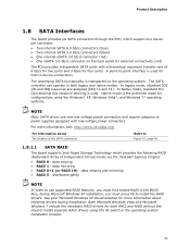
... or power supplies equipped with a theoretical maximum transfer rate of Independent Drives) levels via the Intel H67 Express Chipset: • RAID 0 - A point-to the operating system. In Native mode, standard PCI Conventional bus resource steering is used . Native mode is transparent to -point interface is used for both legacy and native modes. For more information about The location of the SATA connectors Refer to device connections. See your Microsoft Windows XP...
... or power supplies equipped with a theoretical maximum transfer rate of Independent Drives) levels via the Intel H67 Express Chipset: • RAID 0 - A point-to the operating system. In Native mode, standard PCI Conventional bus resource steering is used . Native mode is transparent to -point interface is used for both legacy and native modes. For more information about The location of the SATA connectors Refer to device connections. See your Microsoft Windows XP...
Product Specification
Page 29
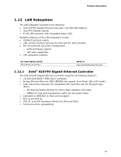
... Express Chipset • RJ-45 LAN connector with integrated status LEDs Additional features of the LAN subsystem include: • CSMA/CD protocol engine • LAN connect interface between the PCH and the LAN controller • PCI Conventional bus power management ⎯ ACPI technology support ⎯ LAN wake capabilities • LAN subsystem software For information about LAN software and drivers Refer to http://downloadcenter.intel.com 1.12.1 Intel® 82579V Gigabit Ethernet Controller The Intel 82579V Gigabit Ethernet Controller supports...
... Express Chipset • RJ-45 LAN connector with integrated status LEDs Additional features of the LAN subsystem include: • CSMA/CD protocol engine • LAN connect interface between the PCH and the LAN controller • PCI Conventional bus power management ⎯ ACPI technology support ⎯ LAN wake capabilities • LAN subsystem software For information about LAN software and drivers Refer to http://downloadcenter.intel.com 1.12.1 Intel® 82579V Gigabit Ethernet Controller The Intel 82579V Gigabit Ethernet Controller supports...

Product Specification
Page 53
... the front panel USB 2.0 headers. Table 31. NOTE • The +5 V DC power on a medium such as a seven-segment display. The POST card can interface with the Low Pin Count (LPC) Debug header. Displaying the POST codes requires a POST card that conforms to I/O port 80h. Technical Reference 2.2.2.6 Front Panel USB 2.0 Headers Figure 12 is fused. • Use only a front panel USB connector that can decode the port and display the contents on the USB headers is a connection diagram for high-speed USB devices.
... the front panel USB 2.0 headers. Table 31. NOTE • The +5 V DC power on a medium such as a seven-segment display. The POST card can interface with the Low Pin Count (LPC) Debug header. Displaying the POST codes requires a POST card that conforms to I/O port 80h. Technical Reference 2.2.2.6 Front Panel USB 2.0 Headers Figure 12 is fused. • Use only a front panel USB connector that can decode the port and display the contents on the USB headers is a connection diagram for high-speed USB devices.

Product Specification
Page 63
... BIOSs are identified as BLH6710H.86A. Maintenance Main Configuration Performance Security Power Boot Exit NOTE The maintenance menu is displayed only when the board is powered-up, the BIOS compares the CPU version and the microcode version in configure mode. Section 2.3 on page 54 shows how to view and change the BIOS settings for the computer. The SPI Flash contains the BIOS Setup program, POST, the PCI auto-configuration utility, LAN EEPROM information, and Plug and Play support.
... BIOSs are identified as BLH6710H.86A. Maintenance Main Configuration Performance Security Power Boot Exit NOTE The maintenance menu is displayed only when the board is powered-up, the BIOS compares the CPU version and the microcode version in configure mode. Section 2.3 on page 54 shows how to view and change the BIOS settings for the computer. The SPI Flash contains the BIOS Setup program, POST, the PCI auto-configuration utility, LAN EEPROM information, and Plug and Play support.

Product Specification
Page 64
... Desktop Board DH67GD and Intel Desktop Board DH67BL Technical Product Specification Table 39 lists the BIOS Setup program menu features. BIOS Setup Program Menu Bar Maintenance Main Configura- tion Performance Clears passwords and displays processor information Displays processor and memory configuration Configures advanced features available through the chipset Configures Memory, Bus and Processor overrides Security Sets passwords and security features Power Configures power management features and power supply controls Boot Selects boot options Exit Saves or discards changes...
... Desktop Board DH67GD and Intel Desktop Board DH67BL Technical Product Specification Table 39 lists the BIOS Setup program menu features. BIOS Setup Program Menu Bar Maintenance Main Configura- tion Performance Clears passwords and displays processor information Displays processor and memory configuration Configures advanced features available through the chipset Configures Memory, Bus and Processor overrides Security Sets passwords and security features Power Configures power management features and power supply controls Boot Selects boot options Exit Saves or discards changes...

Product Specification
Page 75
... execution MRC Memory detection PEI phase post MRC execution Recovery Platform DXE driver CPU Initialization (PEI, DXE, SMM) IO Buses: PCI, USB, ISA, ATA etc. 0x5F is an unrecoverable error. For future use Input devices: Keyboard/Mouse. For future use For future use 75 The POST card can interface with PCI. Table 47. Start with the Low Pin Count (LPC) Debug header. Not that can decode the port and display the...
... execution MRC Memory detection PEI phase post MRC execution Recovery Platform DXE driver CPU Initialization (PEI, DXE, SMM) IO Buses: PCI, USB, ISA, ATA etc. 0x5F is an unrecoverable error. For future use Input devices: Keyboard/Mouse. For future use For future use 75 The POST card can interface with PCI. Table 47. Start with the Low Pin Count (LPC) Debug header. Not that can decode the port and display the...


