

Product Specification
Page 8
...3.5 Legacy USB Support 63 3.6 BIOS Updates 64 3.6.1 Language Support 64 3.6.2 Custom Splash Screen 65 3.7 BIOS Recovery 65 3.8 Boot Options 66 3.8.1 Optical Drive Boot 66 3.8.2 Network Boot 66 3.8.3 Booting Without Attached Devices 66 3.8.4 Changing the Default Boot Device During POST 66 3.9 Adjusting Boot Speed 67 3.9.1 Peripheral Selection and Configuration 67 3.9.2 BIOS Boot Optimizations 67 3.10 BIOS Security Features 68 3.11 BIOS Performance Features 69 4 Error Messages and Beep Codes 4.1 Speaker 71 4.2 BIOS Beep Codes 71 4.3 Front-panel Power LED Blink Codes 72 4.4 BIOS...
...3.5 Legacy USB Support 63 3.6 BIOS Updates 64 3.6.1 Language Support 64 3.6.2 Custom Splash Screen 65 3.7 BIOS Recovery 65 3.8 Boot Options 66 3.8.1 Optical Drive Boot 66 3.8.2 Network Boot 66 3.8.3 Booting Without Attached Devices 66 3.8.4 Changing the Default Boot Device During POST 66 3.9 Adjusting Boot Speed 67 3.9.1 Peripheral Selection and Configuration 67 3.9.2 BIOS Boot Optimizations 67 3.10 BIOS Security Features 68 3.11 BIOS Performance Features 69 4 Error Messages and Beep Codes 4.1 Speaker 71 4.2 BIOS Beep Codes 71 4.3 Front-panel Power LED Blink Codes 72 4.4 BIOS...

Product Specification
Page 10
...Processor and Rear Chassis 2 (4-Pin) Fan Headers 46 18. Auxiliary PCI Express Graphics Power Connector 49 22. BIOS Setup Program Menu Bar 62 31. Acceptable Drives/Media Types for a One-Color Power LED 51 24. Boot Device Menu Options 66 34. BIOS Beep Codes 71 36. Typical Port 80h POST Sequence 77 41. Intel Desktop Board DX58OG Technical Product Specification Tables 1. Power States and Targeted System Power 31 9. Front Panel IEEE 1394a Header 45 15. Auxiliary Front Panel Power/Sleep LED Header 47 19. BIOS Setup Configuration Jumper Settings 54 26. Front-panel Power...
...Processor and Rear Chassis 2 (4-Pin) Fan Headers 46 18. Auxiliary PCI Express Graphics Power Connector 49 22. BIOS Setup Program Menu Bar 62 31. Acceptable Drives/Media Types for a One-Color Power LED 51 24. Boot Device Menu Options 66 34. BIOS Beep Codes 71 36. Typical Port 80h POST Sequence 77 41. Intel Desktop Board DX58OG Technical Product Specification Tables 1. Power States and Targeted System Power 31 9. Front Panel IEEE 1394a Header 45 15. Auxiliary Front Panel Power/Sleep LED Header 47 19. BIOS Setup Configuration Jumper Settings 54 26. Front-panel Power...

Product Specification
Page 11
... an internal header for front panel cabling • Intel® BIOS resident in the Serial Peripheral Interface (SPI) Flash device • Support for Advanced Configuration and Power Interface (ACPI), Plug and Play, and System Management BIOS (SMBIOS) • Support for PCI Local Bus Specification Revision 2.2 • Support for PCI Express* Revision 2.0 • Suspend to 24 GB of system memory with 6 DIMMs using 4 Gb memory technology • Support for up to RAM support • Wake on PCI, front panel, CIR, and USB ports continued 11 Legacy I/O Control...
... an internal header for front panel cabling • Intel® BIOS resident in the Serial Peripheral Interface (SPI) Flash device • Support for Advanced Configuration and Power Interface (ACPI), Plug and Play, and System Management BIOS (SMBIOS) • Support for PCI Local Bus Specification Revision 2.2 • Support for PCI Express* Revision 2.0 • Suspend to 24 GB of system memory with 6 DIMMs using 4 Gb memory technology • Support for up to RAM support • Wake on PCI, front panel, CIR, and USB ports continued 11 Legacy I/O Control...

Product Specification
Page 18
... matched memory modules are installed in each of the three memory channels (blue connectors). • Dual channel mode is enabled when two of SDRAM). This mode is installed or the installed memory modules are populated with matched DIMMs. • Single channel (Asymmetric) mode. For information about ... For information about ... Intel Desktop Board DX58OG Technical Product Specification Table 4 lists the supported DIMM configurations. This mode offers the highest throughput for real world applications. Technology and device width...
... matched memory modules are installed in each of the three memory channels (blue connectors). • Dual channel mode is enabled when two of SDRAM). This mode is installed or the installed memory modules are populated with matched DIMMs. • Single channel (Asymmetric) mode. For information about ... For information about ... Intel Desktop Board DX58OG Technical Product Specification Table 4 lists the supported DIMM configurations. This mode offers the highest throughput for real world applications. Technology and device width...

Product Specification
Page 21
... Marvel 88SE9128 controller (blue) 1.6.2.1 Serial ATA Support The board's Serial ATA controller offers eight independent Serial ATA ports. For information about installing drivers during Microsoft Windows XP installation, you must press F6 to use new low-voltage power connectors and require adapters or power supplies equipped with low-voltage power connectors. In legacy mode, standard IDE I/O and IRQ resources are assigned (IRQ 14 and 15). Also, during installation. 21 One device can operate in the BIOS. A point...
... Marvel 88SE9128 controller (blue) 1.6.2.1 Serial ATA Support The board's Serial ATA controller offers eight independent Serial ATA ports. For information about installing drivers during Microsoft Windows XP installation, you must press F6 to use new low-voltage power connectors and require adapters or power supplies equipped with low-voltage power connectors. In legacy mode, standard IDE I/O and IRQ resources are assigned (IRQ 14 and 15). Also, during installation. 21 One device can operate in the BIOS. A point...

Product Specification
Page 25
... LAN connector with integrated status LEDs Additional features of the LAN subsystem include: • CSMA/CD protocol engine • LAN connect interface between ICH10R and the LAN controller • Conventional PCI bus power management ⎯ ACPI technology support ⎯ LAN wake capabilities • LAN subsystem software For information about LAN software and drivers Refer to http://downloadcenter.intel.com 1.10.1 Intel® 82567L Gigabit Ethernet Controller The Intel 82567L Gigabit Ethernet Controller support the following features: • PCI Express...
... LAN connector with integrated status LEDs Additional features of the LAN subsystem include: • CSMA/CD protocol engine • LAN connect interface between ICH10R and the LAN controller • Conventional PCI bus power management ⎯ ACPI technology support ⎯ LAN wake capabilities • LAN subsystem software For information about LAN software and drivers Refer to http://downloadcenter.intel.com 1.10.1 Intel® 82567L Gigabit Ethernet Controller The Intel 82567L Gigabit Ethernet Controller support the following features: • PCI Express...
Product Specification
Page 52
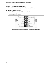
Figure 13. Connection Diagram for high-speed USB devices. Intel Desktop Board DX58OG Technical Product Specification 2.2.2.6 Front Panel USB Headers Figure 13 is a connection diagram for the front panel USB headers. # INTEGRATOR'S NOTES • The +5 V DC power on the USB headers is fused. • Use only a front panel USB connector that conforms to the USB 2.0 specification for Front Panel USB Headers 52
Figure 13. Connection Diagram for high-speed USB devices. Intel Desktop Board DX58OG Technical Product Specification 2.2.2.6 Front Panel USB Headers Figure 13 is a connection diagram for the front panel USB headers. # INTEGRATOR'S NOTES • The +5 V DC power on the USB headers is fused. • Use only a front panel USB connector that conforms to the USB 2.0 specification for Front Panel USB Headers 52

Product Specification
Page 62
... resources. Intel Desktop Board DX58OG Technical Product Specification Table 30 lists the BIOS Setup program menu features. BIOS Setup Program Menu Bar Maintenance Main Advanced Performance Security Clears passwords and displays processor information Displays processor and memory configuration Configures advanced features available through the chipset Configures Memory, Bus and Processor overrides Sets passwords and security features Power Configures power management features and power supply controls Boot Selects boot options Exit Saves or discards changes to configure the...
... resources. Intel Desktop Board DX58OG Technical Product Specification Table 30 lists the BIOS Setup program menu features. BIOS Setup Program Menu Bar Maintenance Main Advanced Performance Security Clears passwords and displays processor information Displays processor and memory configuration Configures advanced features available through the chipset Configures Memory, Bus and Processor overrides Sets passwords and security features Power Configures power management features and power supply controls Boot Selects boot options Exit Saves or discards changes to configure the...

Product Specification
Page 73
Displaying the POST codes requires a PCI bus add-in PCI bus connector 1. The following tables provide information about the POST codes generated by any PEIM/driver for future use (new output console codes). 90 - 9F Input devices: Keyboard/Mouse. 9F is left at port 80h. Reserved for debug. 10 - 1F Host Processors: 1F is an unrecoverable CPU error. 20 - 2F Memory/Chipset: 2F is an unrecoverable error. A0 - C0 - See Table 39. F0...
Displaying the POST codes requires a PCI bus add-in PCI bus connector 1. The following tables provide information about the POST codes generated by any PEIM/driver for future use (new output console codes). 90 - 9F Input devices: Keyboard/Mouse. 9F is left at port 80h. Reserved for debug. 10 - 1F Host Processors: 1F is an unrecoverable CPU error. 20 - 2F Memory/Chipset: 2F is an unrecoverable error. A0 - C0 - See Table 39. F0...
Product Specification
Page 77
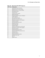
Error Messages and Beep Codes Table 40. Typical Port 80h POST Sequence POST Code Description 21 Initializing a chipset component 22 Reading SPD from memory DIMMs 23 Detecting presence of memory DIMMs 25 Configuring memory 28 Testing memory 34 Loading recovery capsule E4 Entered DXE phase 12 Starting application processor initialization 13 SMM initialization 50 Enumerating PCI busses 51 Allocating resourced to PCI bus 92 Detecting the presence of the keyboard 90 Resetting keyboard 94 Clearing keyboard input...
Error Messages and Beep Codes Table 40. Typical Port 80h POST Sequence POST Code Description 21 Initializing a chipset component 22 Reading SPD from memory DIMMs 23 Detecting presence of memory DIMMs 25 Configuring memory 28 Testing memory 34 Loading recovery capsule E4 Entered DXE phase 12 Starting application processor initialization 13 SMM initialization 50 Enumerating PCI busses 51 Allocating resourced to PCI bus 92 Detecting the presence of the keyboard 90 Resetting keyboard 94 Clearing keyboard input...
English Product Guide
Page 3
.... It is intended for installation in this manual: CAUTION Cautions warn the user about how to prevent damage to hardware or loss of product features 2 Installing and Replacing Desktop Board Components: instructions on how to update the BIOS 4 Configuring for RAID: information about configuring your system for Intel® Desktop Board DX58OG. iii Use Only for Intended Applications All Intel Desktop Boards are evaluated as Information Technology Equipment (I.T.E.) for use in personal computers...
.... It is intended for installation in this manual: CAUTION Cautions warn the user about how to prevent damage to hardware or loss of product features 2 Installing and Replacing Desktop Board Components: instructions on how to update the BIOS 4 Configuring for RAID: information about configuring your system for Intel® Desktop Board DX58OG. iii Use Only for Intended Applications All Intel Desktop Boards are evaluated as Information Technology Equipment (I.T.E.) for use in personal computers...
English Product Guide
Page 6
...USB 2.0 Headers 49 Alternate Front Panel Power LED Header 50 Front Panel Header 50 Connecting to the Audio System 51 Connecting Chassis Fan and Power Supply Cables 52 Connecting Chassis Fan Cables 52 Connecting Power Supply Cables 53 Setting the BIOS Configuration Jumper 54 Clearing Passwords 55 Replacing the Battery 56 Installing the WiFi/Bluetooth* Module in a Desktop Chassis 61 3 Updating the BIOS Updating the BIOS with the Intel® Express BIOS Update Utility 63 Updating the BIOS Using the F7 Function Key 64 Updating the BIOS with the Intel® Flash Memory Update Utility...
...USB 2.0 Headers 49 Alternate Front Panel Power LED Header 50 Front Panel Header 50 Connecting to the Audio System 51 Connecting Chassis Fan and Power Supply Cables 52 Connecting Chassis Fan Cables 52 Connecting Power Supply Cables 53 Setting the BIOS Configuration Jumper 54 Clearing Passwords 55 Replacing the Battery 56 Installing the WiFi/Bluetooth* Module in a Desktop Chassis 61 3 Updating the BIOS Updating the BIOS with the Intel® Express BIOS Update Utility 63 Updating the BIOS Using the F7 Function Key 64 Updating the BIOS with the Intel® Flash Memory Update Utility...
English Product Guide
Page 7
... 85 Ensure Electromagnetic Compatibility (EMC) Compliance 85 Product Certifications 86 Board-Level Certifications 86 Chassis- Intel Desktop Board DX58OG Mounting Screw Hole Locations 32 9. Close the Load Plate 36 14. Connecting the Processor Fan Heat Sink Cable to BIOS Button 20 4. Onboard Power and Reset Switches 25 6. Unlatch the Socket Lever 33 10. Location of the Standby Power Indicator 24 5. Install the Processor 35 13. Location of the Diagnostic/Status LEDs 26 7. Example Configuration Using Three DIMMs 38...
... 85 Ensure Electromagnetic Compatibility (EMC) Compliance 85 Product Certifications 86 Board-Level Certifications 86 Chassis- Intel Desktop Board DX58OG Mounting Screw Hole Locations 32 9. Close the Load Plate 36 14. Connecting the Processor Fan Heat Sink Cable to BIOS Button 20 4. Onboard Power and Reset Switches 25 6. Unlatch the Socket Lever 33 10. Location of the Standby Power Indicator 24 5. Install the Processor 35 13. Location of the Diagnostic/Status LEDs 26 7. Example Configuration Using Three DIMMs 38...
English Product Guide
Page 8
... BIOS Setup Program Modes 55 14. Front-panel Power LED Blink Codes 71 16. EMC Regulations 83 20. Connecting Power Supply Cables 53 27. Installing the WiFi/Bluetooth Module 62 30. Intel Desktop Board DX58OG China RoHS Material Self Declaration Table 82 Tables 1. Feature Summary 9 2. Alternate Front Panel Power LED Header Signal Names 50 12. BIOS Beep Codes 71 15. Port 80h POST Codes 74 18. Installing Linked PCI Express Graphics Cards 44 22. Location of the BIOS Configuration Jumper Block 54 28. Location of the Chassis Fan Headers...
... BIOS Setup Program Modes 55 14. Front-panel Power LED Blink Codes 71 16. EMC Regulations 83 20. Connecting Power Supply Cables 53 27. Installing the WiFi/Bluetooth Module 62 30. Intel Desktop Board DX58OG China RoHS Material Self Declaration Table 82 Tables 1. Feature Summary 9 2. Alternate Front Panel Power LED Header Signal Names 50 12. BIOS Beep Codes 71 15. Port 80h POST Codes 74 18. Installing Linked PCI Express Graphics Cards 44 22. Location of the BIOS Configuration Jumper Block 54 28. Location of the Chassis Fan Headers...

English Product Guide
Page 19
... be updated by specifying manual configuration in Chapter 3. For instructions on resetting the password, go to boot the computer. Desktop Board Features BIOS The BIOS provides the Power-On Self-Test (POST), the BIOS Setup program, and the PCI/PCI Express and IDE auto-configuration utilities. You do not need to view and change all Setup options. If both the supervisor and user passwords are set for the BIOS Setup and for your computer, the PCI/PCI Express auto-configuration utility in the Serial Peripheral Interface (SPI) Flash device...
... be updated by specifying manual configuration in Chapter 3. For instructions on resetting the password, go to boot the computer. Desktop Board Features BIOS The BIOS provides the Power-On Self-Test (POST), the BIOS Setup program, and the PCI/PCI Express and IDE auto-configuration utilities. You do not need to view and change all Setup options. If both the supervisor and user passwords are set for the BIOS Setup and for your computer, the PCI/PCI Express auto-configuration utility in the Serial Peripheral Interface (SPI) Flash device...
English Product Guide
Page 29
... shield • Install and remove the Desktop Board • Install and remove a processor • Install and remove memory • Install and remove a PCI Express x16 card • Connect the Serial ATA cables • Connect to the internal headers and connectors • Connect to the audio system • Connect chassis fan and power supply cables • Set the BIOS configuration jumper • Clear passwords • Replace the battery • Install the WiFi/BlueTooth Module Before You Begin CAUTIONS The procedures in this chapter only at an ESD workstation using and modifying...
... shield • Install and remove the Desktop Board • Install and remove a processor • Install and remove memory • Install and remove a PCI Express x16 card • Connect the Serial ATA cables • Connect to the internal headers and connectors • Connect to the audio system • Connect chassis fan and power supply cables • Set the BIOS configuration jumper • Clear passwords • Replace the battery • Install the WiFi/BlueTooth Module Before You Begin CAUTIONS The procedures in this chapter only at an ESD workstation using and modifying...
English Product Guide
Page 55
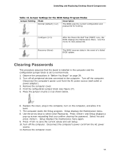
.... Setup displays the Maintenance menu. 8. Turn off all peripheral devices connected to select Clear Passwords. Installing and Replacing Desktop Board Components Table 13. Configure (2-3) Recovery (None) After the Power-On Self-Test (POST) runs, the BIOS displays the Maintenance Menu. Remove the computer cover. 55 Press to clear passwords. Turn off the computer. The computer starts the Setup program. Jumper Settings for the BIOS Setup Program Modes Jumper Setting Mode Normal (default) (1-2) Description The BIOS uses the current configuration and passwords for booting. Use...
.... Setup displays the Maintenance menu. 8. Turn off all peripheral devices connected to select Clear Passwords. Installing and Replacing Desktop Board Components Table 13. Configure (2-3) Recovery (None) After the Power-On Self-Test (POST) runs, the BIOS displays the Maintenance Menu. Remove the computer cover. 55 Press to clear passwords. Turn off the computer. The computer starts the Setup program. Jumper Settings for the BIOS Setup Program Modes Jumper Setting Mode Normal (default) (1-2) Description The BIOS uses the current configuration and passwords for booting. Use...

English Product Guide
Page 68
...the Intel Matrix Storage Technology RAID Driver in : "Configuring the BIOS" and "Loading the Intel Matrix Storage Technology RAID Drivers and Software." Install the Intel® ICH10R SATA RAID Controller driver. 3. Install the Intel Matrix Storage Console software via the Intel Express Installer CD included with your Desktop Board or after downloading it from the Windows installation CD. 2. Follow the steps described above in a USB floppy disk drive. Begin Windows Setup by booting from the Internet at http://www.intel.com/p/en_US/support?iid=hdr+support. At the beginning of Windows Setup...
...the Intel Matrix Storage Technology RAID Driver in : "Configuring the BIOS" and "Loading the Intel Matrix Storage Technology RAID Drivers and Software." Install the Intel® ICH10R SATA RAID Controller driver. 3. Install the Intel Matrix Storage Console software via the Intel Express Installer CD included with your Desktop Board or after downloading it from the Windows installation CD. 2. Follow the steps described above in a USB floppy disk drive. Begin Windows Setup by booting from the Internet at http://www.intel.com/p/en_US/support?iid=hdr+support. At the beginning of Windows Setup...
English Product Guide
Page 69
... Configuration Secondary SATA Controller; Install the Marvell 88SE61XX SATA RAID Controller driver. 3. Use the arrow keys to the Desktop Board's two back panel eSATA connectors. 2. Press once you will see the following Marvell Storage Manager option ROM status message on the remaining portion of Windows Setup, press to the EXIT option in a USB floppy disk drive. Select the strip size, if necessary, and press . 5. Loading the Marvell Storage Technology RAID Drivers and Software 1. Upon re-boot, you have selected the RAID LEVEL. 4. Enter system BIOS Setup...
... Configuration Secondary SATA Controller; Install the Marvell 88SE61XX SATA RAID Controller driver. 3. Use the arrow keys to the Desktop Board's two back panel eSATA connectors. 2. Press once you will see the following Marvell Storage Manager option ROM status message on the remaining portion of Windows Setup, press to the EXIT option in a USB floppy disk drive. Select the strip size, if necessary, and press . 5. Loading the Marvell Storage Technology RAID Drivers and Software 1. Upon re-boot, you have selected the RAID LEVEL. 4. Enter system BIOS Setup...

English Product Guide
Page 71
... and pause) until the BIOS update is powered off for 0.5 seconds. A Error Messages and Indicators Intel Desktop Board DX58OG reports POST errors in progress Off when the update begins, then on the monitor • By displaying diagnostic progress codes (POST codes) BIOS Error Codes Whenever a recoverable error occurs during POST, the BIOS causes the board's speaker to beep and the front panel power LED to blink an error message indicating the problem (see Table 14). POST complete One 0.5 second beep when POST completes.
... and pause) until the BIOS update is powered off for 0.5 seconds. A Error Messages and Indicators Intel Desktop Board DX58OG reports POST errors in progress Off when the update begins, then on the monitor • By displaying diagnostic progress codes (POST codes) BIOS Error Codes Whenever a recoverable error occurs during POST, the BIOS causes the board's speaker to beep and the front panel power LED to blink an error message indicating the problem (see Table 14). POST complete One 0.5 second beep when POST completes.


