
English Product Guide
Page 6
Intel Desktop Board DX58OG Product Guide 2 Installing and Replacing Desktop Board Components Before You Begin 29 Installation Precautions 30 Prevent Power Supply Overload 30 Observe Safety and Regulatory Requirements 30 Installing the I/O Shield 31 Installing and Removing the Desktop Board 32 Installing and Removing a Processor 33 Installing a ...Battery 56 Installing the WiFi/Bluetooth* Module in a Desktop Chassis 61 3 Updating the BIOS Updating the BIOS with the Intel® Express BIOS Update Utility 63 Updating the BIOS Using the F7 Function Key 64 Updating the BIOS with the...
Intel Desktop Board DX58OG Product Guide 2 Installing and Replacing Desktop Board Components Before You Begin 29 Installation Precautions 30 Prevent Power Supply Overload 30 Observe Safety and Regulatory Requirements 30 Installing the I/O Shield 31 Installing and Removing the Desktop Board 32 Installing and Removing a Processor 33 Installing a ...Battery 56 Installing the WiFi/Bluetooth* Module in a Desktop Chassis 61 3 Updating the BIOS Updating the BIOS with the Intel® Express BIOS Update Utility 63 Updating the BIOS Using the F7 Function Key 64 Updating the BIOS with the...
English Product Guide
Page 7
...Lift the Load Plate 34 11. Install the Processor 35 13. Close the Load Plate 36 14. Installing the I/O Shield 31 8. Intel Desktop Board DX58OG Mounting Screw Hole Locations 32 9. Example Configuration Using Three DIMMs 38 vii LAN Connector LEDs 17 3. Onboard Power and Reset... 5. Remove the Processor from the Protective Processor Cover 35 12. Intel Desktop Board DX58OG Components 12 2. Location of the Diagnostic/Status LEDs 26 7. Contents 4 Configuring for RAID Configuring for RAID Using Intel® Matrix Storage Technology 67 Configuring the BIOS 67 Creating Your...
...Lift the Load Plate 34 11. Install the Processor 35 13. Close the Load Plate 36 14. Installing the I/O Shield 31 8. Intel Desktop Board DX58OG Mounting Screw Hole Locations 32 9. Example Configuration Using Three DIMMs 38 vii LAN Connector LEDs 17 3. Onboard Power and Reset... 5. Remove the Processor from the Protective Processor Cover 35 12. Intel Desktop Board DX58OG Components 12 2. Location of the Diagnostic/Status LEDs 26 7. Contents 4 Configuring for RAID Configuring for RAID Using Intel® Matrix Storage Technology 67 Configuring the BIOS 67 Creating Your...
English Product Guide
Page 29
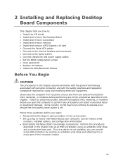
2 Installing and Replacing Desktop Board Components This chapter tells you how to: • Install the I/O shield • Install and remove the Desktop Board • Install and remove a processor • Install and remove memory • Install and remove a PCI Express x16 card &#...
2 Installing and Replacing Desktop Board Components This chapter tells you how to: • Install the I/O shield • Install and remove the Desktop Board • Install and remove a processor • Install and remove memory • Install and remove a PCI Express x16 card &#...
English Product Guide
Page 31
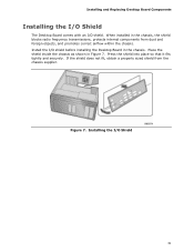
... dust and foreign objects, and promotes correct airflow within the chassis. Installing and Replacing Desktop Board Components Installing the I/O Shield The Desktop Board comes with an I /O Shield 31 Place the shield inside the chassis as shown in the chassis, the shield blocks radio frequency transmissions, protects internal components from the chassis supplier. Press the...
... dust and foreign objects, and promotes correct airflow within the chassis. Installing and Replacing Desktop Board Components Installing the I/O Shield The Desktop Board comes with an I /O Shield 31 Place the shield inside the chassis as shown in the chassis, the shield blocks radio frequency transmissions, protects internal components from the chassis supplier. Press the...
English Product Guide
Page 49
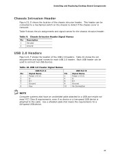
... (+5 V) DD+ Ground No Connection NOTE Computer systems that meets the requirements for each USB 2.0 header. Each USB header can be used to the cable. Use a shielded cable that have an unshielded cable attached to a USB port might not meet FCC Class B requirements, even if no device or a low-speed USB device...
... (+5 V) DD+ Ground No Connection NOTE Computer systems that meets the requirements for each USB 2.0 header. Each USB header can be used to the cable. Use a shielded cable that have an unshielded cable attached to a USB port might not meet FCC Class B requirements, even if no device or a low-speed USB device...
English Product Guide
Page 85
... Class B Statement translation: This equipment is for the host chassis, power supply, and other modules: • Product certifications or lack of certifications • External I/O cable shielding and filtering • Mounting, grounding, and bonding requirements • Keying connectors when mating the wrong connectors could be hazardous If the power supply and other...
... Class B Statement translation: This equipment is for the host chassis, power supply, and other modules: • Product certifications or lack of certifications • External I/O cable shielding and filtering • Mounting, grounding, and bonding requirements • Keying connectors when mating the wrong connectors could be hazardous If the power supply and other...