
Technical Product Specification
Page 9
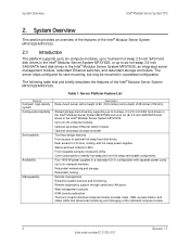
... ports. Up to six hot-swap 3.5-inch SAS/SATA hard disk drives in a redundant (3+1) configuration with a height of 6U (10.5 inches) and a depth of the Intel® Modular Server System MFSYS25/MFSYS35. 2.1 Introduction The platform supports up to six compute modules,... console redirection. Extensive system sensors and monitoring. Table 1. Optional secondary storage controller. The server ships configured for rack mounting, but may be mounted in the Intel® Modular Server System MFSYS35. Optional secondary Ethernet switch module. Server Platform Feature List Feature Compact,...
... ports. Up to six hot-swap 3.5-inch SAS/SATA hard disk drives in a redundant (3+1) configuration with a height of 6U (10.5 inches) and a depth of the Intel® Modular Server System MFSYS25/MFSYS35. 2.1 Introduction The platform supports up to six compute modules,... console redirection. Extensive system sensors and monitoring. Table 1. Optional secondary storage controller. The server ships configured for rack mounting, but may be mounted in the Intel® Modular Server System MFSYS35. Optional secondary Ethernet switch module. Server Platform Feature List Feature Compact,...
Technical Product Specification
Page 10
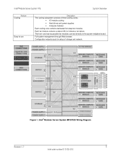
Full system management through Web browser. Intel® Modular Server System MFSYS25 Wiring Diagram Revision 1.7 3 Intel order number E15155-010 The front- and rear-accessible fan modules connect directly to indicate a fan failure. Configuration wizards assist in setup of three cooling zones. ƒ I/O module cooling ƒ Hard drives and power supplies ƒ Compute modules...
Full system management through Web browser. Intel® Modular Server System MFSYS25 Wiring Diagram Revision 1.7 3 Intel order number E15155-010 The front- and rear-accessible fan modules connect directly to indicate a fan failure. Configuration wizards assist in setup of three cooling zones. ƒ I/O module cooling ƒ Hard drives and power supplies ƒ Compute modules...
Technical Product Specification
Page 15
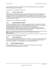
...module fail although any changes to support the external hard disks in a (1+1) cooling redundancy. System Overview Intel® Modular Server System TPS switch module is the minimum configuration for external networking, with a second storage controller allowing storage controller redundancy. One storage controller is maintained ... that operate in the front storage enclosure. Cooling module 1 cools compute modules 1-3; Storage controller failures are connected. 8 Revision 1.7 Intel order number E15155-010 See Section 3.5 for Intel® Modular Server System MFSYS25V2 only.
...module fail although any changes to support the external hard disks in a (1+1) cooling redundancy. System Overview Intel® Modular Server System TPS switch module is the minimum configuration for external networking, with a second storage controller allowing storage controller redundancy. One storage controller is maintained ... that operate in the front storage enclosure. Cooling module 1 cools compute modules 1-3; Storage controller failures are connected. 8 Revision 1.7 Intel order number E15155-010 See Section 3.5 for Intel® Modular Server System MFSYS25V2 only.
Technical Product Specification
Page 18
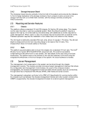
... of all modules. The rails attach to the back of the I/O slots. This module provides a browser-based management interface that allows the configuration and management of all components in the system can be rack-mounted or used in a rack, the chassis may be done through Ethernet) ...RAID functionality. 2.5 Mounting and Service Features 2.5.1 Chassis The platform utilizes a standard 19-inch EIA chassis, 6U high by 28 inches deep. The Intel® Modular Server System MFSYS25/MFSYS35 uses fixed rails. The 6U height is supported by 34 inches deep, with an optional rail kit. All...
... of all modules. The rails attach to the back of the I/O slots. This module provides a browser-based management interface that allows the configuration and management of all components in the system can be rack-mounted or used in a rack, the chassis may be done through Ethernet) ...RAID functionality. 2.5 Mounting and Service Features 2.5.1 Chassis The platform utilizes a standard 19-inch EIA chassis, 6U high by 28 inches deep. The Intel® Modular Server System MFSYS25/MFSYS35 uses fixed rails. The 6U height is supported by 34 inches deep, with an optional rail kit. All...
Technical Product Specification
Page 20
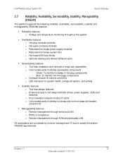
Revision 1.7 13 Intel order number E15155-010 Intel® Modular Server System TPS System Overview 2.7 Reliability, Availability, Serviceability, Usability, Manageability (RASUM) The platform supports the following reliability, availability, serviceability, ...to satisfy the system RASUM requirements. Blue: To identify non-hot-swap components o Compute module ID buttons and LEDs o LED indicators for system health, configured options, and activity ƒ Usability features o Tool-less design features o External access to hot-swap hard disk drives, power supplies, LEDs and switches...
Revision 1.7 13 Intel order number E15155-010 Intel® Modular Server System TPS System Overview 2.7 Reliability, Availability, Serviceability, Usability, Manageability (RASUM) The platform supports the following reliability, availability, serviceability, ...to satisfy the system RASUM requirements. Blue: To identify non-hot-swap components o Compute module ID buttons and LEDs o LED indicators for system health, configured options, and activity ƒ Usability features o Tool-less design features o External access to hot-swap hard disk drives, power supplies, LEDs and switches...

Technical Product Specification
Page 21
... - 6U Width Depth Weight (full configuration) Value 10.3 inches 261.4 mm 17.5 inches 444.4 mm 28.4 inches 720.2 mm 187 lbs 85 kg The following table describes the physical specifications of the Intel® Modular Server System MFSYS25/MFSYS35.... 3.1.1 Environmental Specifications Summary The following table describes the environmental specifications of the Intel® Modular Server System MFSYS25/MFSYS35 and all components. 14 Revision 1.7 Intel order number E15155-010 Environmental Specifications Summary Environment Temperature operating Temperature non-operating ...
... - 6U Width Depth Weight (full configuration) Value 10.3 inches 261.4 mm 17.5 inches 444.4 mm 28.4 inches 720.2 mm 187 lbs 85 kg The following table describes the physical specifications of the Intel® Modular Server System MFSYS25/MFSYS35.... 3.1.1 Environmental Specifications Summary The following table describes the environmental specifications of the Intel® Modular Server System MFSYS25/MFSYS35 and all components. 14 Revision 1.7 Intel order number E15155-010 Environmental Specifications Summary Environment Temperature operating Temperature non-operating ...

Technical Product Specification
Page 33
Chassis Management Module 2 Block Diagram 3.5.4 Drawings The following figure shows the front view of Chassis Management Module 3.5.5 Architectural Overview The chassis management module provides configuration and management capabilities for the entire Intel® Modular Server System MFSYS25/MFSYS35. Front View of the CMM. The CMM runs the Web browser- 26 Revision 1.7 Intel order number E15155-010 System Details Intel® Modular Server System TPS Figure 18. Figure 19.
Chassis Management Module 2 Block Diagram 3.5.4 Drawings The following figure shows the front view of Chassis Management Module 3.5.5 Architectural Overview The chassis management module provides configuration and management capabilities for the entire Intel® Modular Server System MFSYS25/MFSYS35. Front View of the CMM. The CMM runs the Web browser- 26 Revision 1.7 Intel order number E15155-010 System Details Intel® Modular Server System TPS Figure 18. Figure 19.
Technical Product Specification
Page 34
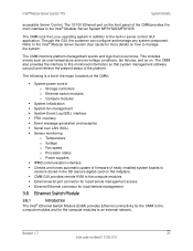
... conditions, fan failures, and so on how to this monitored information so that system management software can configure and manage any system component. Refer to the Intel® Modular Server System User Guide for the compute modules to an external network. The following is ...serial port connector for local/remote management access ƒ External Ethernet connector for local/remote management 3.6 Ethernet Switch Module 3.6.1 Introduction The Intel® Ethernet Switch Module (ESM) provides Ethernet connectivity for the CMM to the compute modules and for more details on . Through...
... conditions, fan failures, and so on how to this monitored information so that system management software can configure and manage any system component. Refer to the Intel® Modular Server System User Guide for the compute modules to an external network. The following is ...serial port connector for local/remote management access ƒ External Ethernet connector for local/remote management 3.6 Ethernet Switch Module 3.6.1 Introduction The Intel® Ethernet Switch Module (ESM) provides Ethernet connectivity for the CMM to the compute modules and for more details on . Through...
Technical Product Specification
Page 36
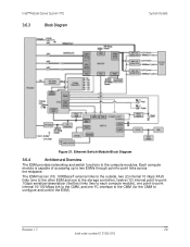
... the compute modules. Ethernet Switch Module Block Diagram 3.6.4 Architectural Overview The ESM provides networking and switch functions to -point links across the midplane. Revision 1.7 29 Intel order number E15155-010 The ESM has ten (10) 1000BaseT external links to the outside, two (2) internal 10 Gbps XAUI links (one to the other... compute module), one point-to-point internal 10/100 Mbps link to the CMM, and one I²C interface to the CMM (for the CMM to configure and control the ESM). Intel® Modular Server System TPS 3.6.3 Block Diagram System Details Figure 21.
... the compute modules. Ethernet Switch Module Block Diagram 3.6.4 Architectural Overview The ESM provides networking and switch functions to -point links across the midplane. Revision 1.7 29 Intel order number E15155-010 The ESM has ten (10) 1000BaseT external links to the outside, two (2) internal 10 Gbps XAUI links (one to the other... compute module), one point-to-point internal 10/100 Mbps link to the CMM, and one I²C interface to the CMM (for the CMM to configure and control the ESM). Intel® Modular Server System TPS 3.6.3 Block Diagram System Details Figure 21.
Technical Product Specification
Page 37
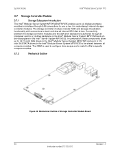
...; Modular Server System MFSYS25/MFSYS35 enables up to 6 3.5inch SAS/SATA drives in the Intel® Server System MFSYS35. Connectivity between all compute modules. The CMM is used to configure drive arrays and to match LUNs to be shared between the storage controller modules and the disk ...drive backplane is achieved through SAS connections to a 14-drive backplane in the Intel® Modular Server System MFSYS25 and a 6drive backplane...
...; Modular Server System MFSYS25/MFSYS35 enables up to 6 3.5inch SAS/SATA drives in the Intel® Server System MFSYS35. Connectivity between all compute modules. The CMM is used to configure drive arrays and to match LUNs to be shared between the storage controller modules and the disk ...drive backplane is achieved through SAS connections to a 14-drive backplane in the Intel® Modular Server System MFSYS25 and a 6drive backplane...

Technical Product Specification
Page 39
...passed back to control 5 V and 12 V power. 3.8 Power Supply Module The power supply module in groups of 4-4-2-2-2 (for 2.5-inch configurations). Expanders send appropriate command/signal to an optional SATA active/active MUX dongle card on disk drive carriers to the SCM through four power cords.... 32 Revision 1.7 Intel order number E15155-010 The power subsystem is configured as serial and version numbers for fully configured platforms, which the SCM uses to provide +5 V and +12 V for optional hot-swap ...
...passed back to control 5 V and 12 V power. 3.8 Power Supply Module The power supply module in groups of 4-4-2-2-2 (for 2.5-inch configurations). Expanders send appropriate command/signal to an optional SATA active/active MUX dongle card on disk drive carriers to the SCM through four power cords.... 32 Revision 1.7 Intel order number E15155-010 The power subsystem is configured as serial and version numbers for fully configured platforms, which the SCM uses to provide +5 V and +12 V for optional hot-swap ...
Technical Product Specification
Page 47
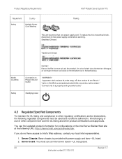
... must be used and conditions adhered to a properly earth grounded outlet." You can find updated product information for configurations on liitettŠvä suojamaadoituskoskettimilla varustettuun pistorasiaan." "Connect only to . Product Regulatory Requirements Intel® Modular Server System TPS Requirement Country Safety Multiple Power Cord Marking Marking This unit has more than one...
... must be used and conditions adhered to a properly earth grounded outlet." You can find updated product information for configurations on liitettŠvä suojamaadoituskoskettimilla varustettuun pistorasiaan." "Connect only to . Product Regulatory Requirements Intel® Modular Server System TPS Requirement Country Safety Multiple Power Cord Marking Marking This unit has more than one...

Technical Product Specification
Page 48
Total server configuration is responsible for a Class A digital device, pursuant to Part... printers, and so on , the user is encouraged to try to radio communications. Revision 1.7 41 Intel order number E15155-010 Intel® Modular Server System TPS Product Regulatory Requirements 3. Peripheral Storage Devices: Must be determined by turning ...to peripherals that may cause harmful interference to correct the interference by the grantee of the FCC Rules. Intel Corporation 5200 N.E. Any changes or modifications not expressly approved by one device is connected. ƒ Consult ...
Total server configuration is responsible for a Class A digital device, pursuant to Part... printers, and so on , the user is encouraged to try to radio communications. Revision 1.7 41 Intel order number E15155-010 Intel® Modular Server System TPS Product Regulatory Requirements 3. Peripheral Storage Devices: Must be determined by turning ...to peripherals that may cause harmful interference to correct the interference by the grantee of the FCC Rules. Intel Corporation 5200 N.E. Any changes or modifications not expressly approved by one device is connected. ƒ Consult ...

Technical Product Specification
Page 52
... ESD ESM FCC FPGA FRB FRU FSB FWH Gibe GND GUI HDD HL HSC I/O I²C ICMB IDE IEC Definition Advanced Configuration and Power Interface Basic Input/Output System Baseboard Management Controller European Conformity (Conformité Européenne) Special International Committee on... Inter-Integrated Circuit Intelligent Chassis Management Bus Integrated Device Electronics International Electrotechnical Commission Revision 1.7 45 Intel order number E15155-010 Intel® Modular Server System TPS Glossary Glossary This appendix contains important terms used in the preceding sections.
... ESD ESM FCC FPGA FRB FRU FSB FWH Gibe GND GUI HDD HL HSC I/O I²C ICMB IDE IEC Definition Advanced Configuration and Power Interface Basic Input/Output System Baseboard Management Controller European Conformity (Conformité Européenne) Special International Committee on... Inter-Integrated Circuit Intelligent Chassis Management Bus Integrated Device Electronics International Electrotechnical Commission Revision 1.7 45 Intel order number E15155-010 Intel® Modular Server System TPS Glossary Glossary This appendix contains important terms used in the preceding sections.

Technical Product Specification
Page 2
... are designed and tested to sale and/or use in this document. ii Revision 1.4 Intel order number: E15154-007 Updated Updated Updated Updated Updated Updated supported memory configurations Disclaimers Information in medical, life saving, or life sustaining applications. Intel reserves these components when the fully integrated system is the responsibility of these for...
... are designed and tested to sale and/or use in this document. ii Revision 1.4 Intel order number: E15154-007 Updated Updated Updated Updated Updated Updated supported memory configurations Disclaimers Information in medical, life saving, or life sustaining applications. Intel reserves these components when the fully integrated system is the responsibility of these for...

Technical Product Specification
Page 5
... Layout 4 Figure 3. Memory Layout ...9 Figure 7. Single Branch Mode Sparing DIMM Configuration 14 Figure 10. Recommended Four-DIMM Configuration 13 Figure 9. Intel® Modular Server System MFSYS25 40 Revision 1.4 v Intel order number: E15154-007 Component and Connector Location Diagram 3 Figure 2. Recommended Minimum Two-DIMM Memory Configuration 12 Figure 8. Recovery Jumper Blocks 26 Figure 11. Compute Module...
... Layout 4 Figure 3. Memory Layout ...9 Figure 7. Single Branch Mode Sparing DIMM Configuration 14 Figure 10. Recommended Four-DIMM Configuration 13 Figure 9. Intel® Modular Server System MFSYS25 40 Revision 1.4 v Intel order number: E15154-007 Component and Connector Location Diagram 3 Figure 2. Recommended Minimum Two-DIMM Memory Configuration 12 Figure 8. Recovery Jumper Blocks 26 Figure 11. Compute Module...

Technical Product Specification
Page 6
...Pin-out 23 Table 12. Internal 9-pin Serial 'A' Header Pin-out (J1B1 25 Table 13. POST Error Beep Codes 39 vi Revision 1.4 Intel order number: E15154-007 External USB Connector Pin-out 25 Table 14. x8 Single Rank 10 Table 3. PCI Bus Segment Characteristics 16 Table 5.... Maximum 8-DIMM System Memory Configuration - Power Connector Pin-out (J1A1 21 Table 9. List of Tables Intel® Compute Module MFS5000SI TPS List of Tables Table 1. Board Connector Matrix 21 Table 8. POST Error Messages ...
...Pin-out 23 Table 12. Internal 9-pin Serial 'A' Header Pin-out (J1B1 25 Table 13. POST Error Beep Codes 39 vi Revision 1.4 Intel order number: E15154-007 External USB Connector Pin-out 25 Table 14. x8 Single Rank 10 Table 3. PCI Bus Segment Characteristics 16 Table 5.... Maximum 8-DIMM System Memory Configuration - Power Connector Pin-out (J1A1 21 Table 9. List of Tables Intel® Compute Module MFS5000SI TPS List of Tables Table 1. Board Connector Matrix 21 Table 8. POST Error Messages ...

Technical Product Specification
Page 13
... are installed, both front-side bus interfaces, and is installed, it is supported in N and N-1 configurations only. The other socket must be obtained from the Intel® 5000 Series Chipsets Server Board Family Datasheet and the Intel® 5000P Memory Controller Hub External Design Specification. 3.1.1 System Bus Interface The MCH is capable of...
... are installed, both front-side bus interfaces, and is installed, it is supported in N and N-1 configurations only. The other socket must be obtained from the Intel® 5000 Series Chipsets Server Board Family Datasheet and the Intel® 5000P Memory Controller Hub External Design Specification. 3.1.1 System Bus Interface The MCH is capable of...

Technical Product Specification
Page 16
... populated in the following table. 10 Revision 1.4 Intel order number: E15154-007 Table 2. DIMM pairs are populated in pairs. 2BFunctional Architecture Intel® Compute Module MFS5000SI TPS 3.1.3.2 Supported and Nonsupported Memory Configurations The server board design supports up to size, speed... Use of identical DIMMs with the Intel® Compute Module MFS5000SI: DDR2 DIMMs that are not fully buffered are shown in the Intel® Server Configurator Tool. 3.1.3.3 DIMM Population Rules and Supported DIMM Configurations DIMM population rules depend on the ...
... populated in the following table. 10 Revision 1.4 Intel order number: E15154-007 Table 2. DIMM pairs are populated in pairs. 2BFunctional Architecture Intel® Compute Module MFS5000SI TPS 3.1.3.2 Supported and Nonsupported Memory Configurations The server board design supports up to size, speed... Use of identical DIMMs with the Intel® Compute Module MFS5000SI: DDR2 DIMMs that are not fully buffered are shown in the Intel® Server Configurator Tool. 3.1.3.3 DIMM Population Rules and Supported DIMM Configurations DIMM population rules depend on the ...

Technical Product Specification
Page 17
... 1: Sparing supported on Branch1 only 0,1: Sparing supported on both memory branches. Refer to section 3.1.3.2 for system performance reasons, Intel's recommendation is that configuration supports Memory Sparing. An eight-DIMM configuration will perform better than a two-DIMM configuration and should be balanced across both branches Branch 0 Branch 1 Channel A Channel B Channel C Channel D DIMM_A1 DIMM_A2 DIMM_B1 DIMM...
... 1: Sparing supported on Branch1 only 0,1: Sparing supported on both memory branches. Refer to section 3.1.3.2 for system performance reasons, Intel's recommendation is that configuration supports Memory Sparing. An eight-DIMM configuration will perform better than a two-DIMM configuration and should be balanced across both branches Branch 0 Branch 1 Channel A Channel B Channel C Channel D DIMM_A1 DIMM_A2 DIMM_B1 DIMM...