
Specification Update
Page 33
all service events will be removed before placing the Intel® Modular Server System MFSYS25/MFSYS35 in a rack. Installation Guidelines • Review the safety and ESD information at the beginning of this manual and in the appendices. • Use a mechanical lift to left, right, front, ...top, and bottom are based on your server system, review the safety and ESD information at the beginning of this manual and in the appendices. Caution: When removing the system from either the front or...
all service events will be removed before placing the Intel® Modular Server System MFSYS25/MFSYS35 in a rack. Installation Guidelines • Review the safety and ESD information at the beginning of this manual and in the appendices. • Use a mechanical lift to left, right, front, ...top, and bottom are based on your server system, review the safety and ESD information at the beginning of this manual and in the appendices. Caution: When removing the system from either the front or...
Specification Update
Page 35
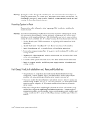
...with at the beginning of this book before removing it from the server system. • Hot-swap cooling modules must also be installed. 3. Review the safety and ESD information at the beginning of this manual and in a rack. Mounting System in Rack Please read the safety information at ...the system, you must remove the rear handles prior to setting the system on components and labels in the rail installation instructions. 7. Intel® Modular Server System Service Guide 19 Install all compute modules, hard drives, power supply modules, I /O modules, and cooling modules. 5.
...with at the beginning of this book before removing it from the server system. • Hot-swap cooling modules must also be installed. 3. Review the safety and ESD information at the beginning of this manual and in a rack. Mounting System in Rack Please read the safety information at ...the system, you must remove the rear handles prior to setting the system on components and labels in the rail installation instructions. 7. Intel® Modular Server System Service Guide 19 Install all compute modules, hard drives, power supply modules, I /O modules, and cooling modules. 5.
Specification Update
Page 36
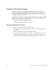
Review the safety and ESD information at the beginning of the chassis (see letter "C" in Figure 10). 20 Intel® Modular Server System Service Guide Remove the Ethernet cable from the module bay (see letter "B" in Figure 10) and pull the module straight out ... module. 3. The management module can only be removed and replaced using the steps detailed in a module bay that device type. Replacing the Management Module The Intel® Modular Server System MFSYS25/MFSYS35 ships with a management module pre-installed in the middle bay of the rear of the management module bay, see...
Review the safety and ESD information at the beginning of the chassis (see letter "C" in Figure 10). 20 Intel® Modular Server System Service Guide Remove the Ethernet cable from the module bay (see letter "B" in Figure 10) and pull the module straight out ... module. 3. The management module can only be removed and replaced using the steps detailed in a module bay that device type. Replacing the Management Module The Intel® Modular Server System MFSYS25/MFSYS35 ships with a management module pre-installed in the middle bay of the rear of the management module bay, see...
Specification Update
Page 37
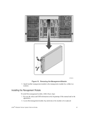
Removing the Management Module 5. Locate the management module bay and remove the module to be replaced. Installing the Management Module To install the management module, follow these steps: 1. C A B AF002436 Figure 10. Intel® Modular Server System Service Guide 21 Install another management module in the appendices. 2. Review the safety and ESD information at the beginning of this manual and in the management module bay within two minutes.
Removing the Management Module 5. Locate the management module bay and remove the module to be replaced. Installing the Management Module To install the management module, follow these steps: 1. C A B AF002436 Figure 10. Intel® Modular Server System Service Guide 21 Install another management module in the appendices. 2. Review the safety and ESD information at the beginning of this manual and in the management module bay within two minutes.
Specification Update
Page 39
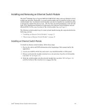
...Switch Module To install an ethernet switch module, follow these steps: 1. An ethernet switch module can only be installed in Figure 12). 4. Review the safety and ESD information at the beginning of this manual and in Figure 12) until the bottom of the Management Module are dedicated ... available switch bay and remove any installed module or filler panel. 3. Slide the switch module into the selected module bay (see Figure 5. Intel® Modular Server System Service Guide 23 The two bays located immediately to the Ethernet Switch Modules and are labeled ESM. Installing and Removing ...
...Switch Module To install an ethernet switch module, follow these steps: 1. An ethernet switch module can only be installed in Figure 12). 4. Review the safety and ESD information at the beginning of this manual and in Figure 12) until the bottom of the Management Module are dedicated ... available switch bay and remove any installed module or filler panel. 3. Slide the switch module into the selected module bay (see Figure 5. Intel® Modular Server System Service Guide 23 The two bays located immediately to the Ethernet Switch Modules and are labeled ESM. Installing and Removing ...

Specification Update
Page 40
... 13). 24 Intel® Modular Server System Service Guide Remove and label the connected Ethernet cables, as is latched. 6. Press the retention latch (see letter "C" in toward the module bay until it is appropriate. Removing an Ethernet Switch Module To remove an ethernet switch module, follow these steps: 1. Review the safety and...
... 13). 24 Intel® Modular Server System Service Guide Remove and label the connected Ethernet cables, as is latched. 6. Press the retention latch (see letter "C" in toward the module bay until it is appropriate. Removing an Ethernet Switch Module To remove an ethernet switch module, follow these steps: 1. Review the safety and...
Specification Update
Page 42
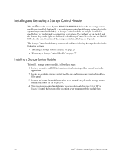
... Control module can only be installed in the appendices. 2. The Storage Control module may be removed and installed using the steps detailed in Figure 14). 4. Review the safety and ESD information at the beginning of this manual and in a module bay that device type. Optionally, a second storage control module may be..., follow these steps: 1. Locate an available storage control module bay and remove any installed module or filler panel. 3. Installing and Removing a Storage Control Module The Intel® Modular Server System MFSYS25/MFSYS35 ships with the module bay. 26...
... Control module can only be installed in the appendices. 2. The Storage Control module may be removed and installed using the steps detailed in Figure 14). 4. Review the safety and ESD information at the beginning of this manual and in a module bay that device type. Optionally, a second storage control module may be..., follow these steps: 1. Locate an available storage control module bay and remove any installed module or filler panel. 3. Installing and Removing a Storage Control Module The Intel® Modular Server System MFSYS25/MFSYS35 ships with the module bay. 26...
Specification Update
Page 43
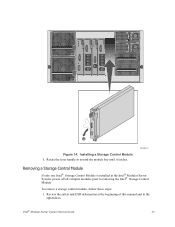
Review the safety and ESD information at the beginning of this manual and in the Intel® Modular Server System, power off all compute modules prior to removing the Intel® Storage Control Module To remove a storage control module, follow these steps: 1. AF002412 Removing a Storage Control Module If only one Intel® Storage Control Module is installed in the appendices. Installing a Storage Control Module 5. B A Figure 14. Rotate the lever handle in toward the module bay until it latches. Intel® Modular Server System Service Guide 27
Review the safety and ESD information at the beginning of this manual and in the Intel® Modular Server System, power off all compute modules prior to removing the Intel® Storage Control Module To remove a storage control module, follow these steps: 1. AF002412 Removing a Storage Control Module If only one Intel® Storage Control Module is installed in the appendices. Installing a Storage Control Module 5. B A Figure 14. Rotate the lever handle in toward the module bay until it latches. Intel® Modular Server System Service Guide 27
Specification Update
Page 45
Review the safety and ESD information at the beginning of the storage control module (see letter "B" in Figure 16) and lift upward (see letter "A" in Figure 16). Warning: You must replace the storage control module with a filler panel or another storage control module within two minutes. 3. Intel® Modular Server System Service Guide...
Review the safety and ESD information at the beginning of the storage control module (see letter "B" in Figure 16) and lift upward (see letter "A" in Figure 16). Warning: You must replace the storage control module with a filler panel or another storage control module within two minutes. 3. Intel® Modular Server System Service Guide...
Specification Update
Page 46
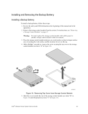
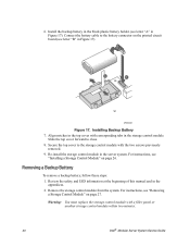
Secure the top cover to the storage control module with a filler panel or another storage control module within two minutes. 30 Intel® Modular Server System Service Guide Review the safety and ESD information at the beginning of this manual and in the server system. Install the backup battery in Figure 17). For...
Secure the top cover to the storage control module with a filler panel or another storage control module within two minutes. 30 Intel® Modular Server System Service Guide Review the safety and ESD information at the beginning of this manual and in the server system. Install the backup battery in Figure 17). For...

Specification Update
Page 49
Review the safety and ESD information at the beginning of the bay (see "Removing a Power Supply Module" on configuration) provide redundancy. To remove a filler module, press ... remove any slot) plus all other modules in the system. Installing a Power Supply Module To install a power supply module, follow these steps: 1. Removing Filler Module Intel® Modular Server System Service Guide 33 B A AF002420 Figure 20. Any additional power supply modules above the minimum required (based on page 34. - Three power...
Review the safety and ESD information at the beginning of the bay (see "Removing a Power Supply Module" on configuration) provide redundancy. To remove a filler module, press ... remove any slot) plus all other modules in the system. Installing a Power Supply Module To install a power supply module, follow these steps: 1. Removing Filler Module Intel® Modular Server System Service Guide 33 B A AF002420 Figure 20. Any additional power supply modules above the minimum required (based on page 34. - Three power...

Specification Update
Page 50
... To remove a power supply module, follow these steps: 1. AF002434 Figure 21. Installing Power Supply Module 4. Locate the power supply module to an appropriate power source. 3. Review the safety and ESD information at the beginning of this manual and in the appendices. 2. Remove the power cord from the power supply module to...
... To remove a power supply module, follow these steps: 1. AF002434 Figure 21. Installing Power Supply Module 4. Locate the power supply module to an appropriate power source. 3. Review the safety and ESD information at the beginning of this manual and in the appendices. 2. Remove the power cord from the power supply module to...
Specification Update
Page 52
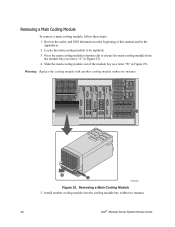
... module bay (see letter "B" in Figure 23). Press the main cooling module retention clip to be replaced. 3. B A AF002438 Figure 23. Review the safety and ESD information at the beginning of the module bay (see letter "A" in the appendices. 2. Removing a Main Cooling Module 5.... Slide the main cooling module out of this manual and in Figure 23). 4. Install another cooling module within two minutes. 36 Intel® Modular Server System Service Guide Warning: Replace the cooling module with another cooling module into the cooling module bay within two minutes....
... module bay (see letter "B" in Figure 23). Press the main cooling module retention clip to be replaced. 3. B A AF002438 Figure 23. Review the safety and ESD information at the beginning of the module bay (see letter "A" in the appendices. 2. Removing a Main Cooling Module 5.... Slide the main cooling module out of this manual and in Figure 23). 4. Install another cooling module within two minutes. 36 Intel® Modular Server System Service Guide Warning: Replace the cooling module with another cooling module into the cooling module bay within two minutes....

Specification Update
Page 53
...cooling module into the unoccupied cooling module bay until the retention latch engages (see Figure 24). Review the safety and ESD information at the front of this manual and in Intel® Modular Server System Service Guide 37 Installing a Main Cooling Module To install a main... cooling module, follow these steps: 1. Installing a Main Cooling Module Replacing the I/O Cooling Module The Intel® Modular Server System MFSYS25/MFSYS35 ships with one I /O Cooling Module in the appendices. 2. AF002439 Figure 24. Locate the cooling module ...
...cooling module into the unoccupied cooling module bay until the retention latch engages (see Figure 24). Review the safety and ESD information at the front of this manual and in Intel® Modular Server System Service Guide 37 Installing a Main Cooling Module To install a main... cooling module, follow these steps: 1. Installing a Main Cooling Module Replacing the I/O Cooling Module The Intel® Modular Server System MFSYS25/MFSYS35 ships with one I /O Cooling Module in the appendices. 2. AF002439 Figure 24. Locate the cooling module ...

Specification Update
Page 54
Review the safety and ESD information at the beginning of the module bay (see letter "A" in Figure 26). 4. Slide the I/O cooling module out of this manual and in Figure 26). 1 2 3 4 5 6 7 8 9 10 11 12 13 14 B A AF003160 Figure 25. Install another cooling module into the cooling module bay within two minutes. 38 Intel... these steps: 1. Press the I/O cooling module retention latch to be replaced. 3. • Intel® Modular Server System MFSYS25, see Figure 3 • Intel® Modular Server System MFSYS35, see Figure 4. Locate the I /O Cooling Module 5. Removing the...
Review the safety and ESD information at the beginning of the module bay (see letter "A" in Figure 26). 4. Slide the I/O cooling module out of this manual and in Figure 26). 1 2 3 4 5 6 7 8 9 10 11 12 13 14 B A AF003160 Figure 25. Install another cooling module into the cooling module bay within two minutes. 38 Intel... these steps: 1. Press the I/O cooling module retention latch to be replaced. 3. • Intel® Modular Server System MFSYS25, see Figure 3 • Intel® Modular Server System MFSYS35, see Figure 4. Locate the I /O Cooling Module 5. Removing the...

Specification Update
Page 55
...to 14 hotswap 2.5-inch SAS hard drives in the Intel® Modular Server System MFSYS25 or 6 hotswap 3.5-inch SAS/SATA hard drives in the appendices. 2. The on-board storage bay supports the installation of up to be replaced. 3. Review the safety and ESD information at the beginning of an... on page 69. Intel® Modular Server System Service Guide 39 For more information, see Figure 26) until the retention latch engages...
...to 14 hotswap 2.5-inch SAS hard drives in the Intel® Modular Server System MFSYS25 or 6 hotswap 3.5-inch SAS/SATA hard drives in the appendices. 2. The on-board storage bay supports the installation of up to be replaced. 3. Review the safety and ESD information at the beginning of an... on page 69. Intel® Modular Server System Service Guide 39 For more information, see Figure 26) until the retention latch engages...

Specification Update
Page 56
... 1. Press the retaining lever on an available drive carrier to the drive carrier. 40 Intel® Modular Server System Service Guide Caution: Only hard drives validated for use in the Intel® Modular Server System MFSYS25/MFSYS35 Tested Hardware and Operating System List. Remove the drive ... not listed in the Intel® Modular Server System MFSYS25/ MFSYS35 should be installed. With a Phillips* screwdriver, remove the four screws securing the filler panel to release the drive carrier from the drive bay module (see letter "A" in Figure 27). Review the safety and ESD ...
... 1. Press the retaining lever on an available drive carrier to the drive carrier. 40 Intel® Modular Server System Service Guide Caution: Only hard drives validated for use in the Intel® Modular Server System MFSYS25/MFSYS35 Tested Hardware and Operating System List. Remove the drive ... not listed in the Intel® Modular Server System MFSYS25/ MFSYS35 should be installed. With a Phillips* screwdriver, remove the four screws securing the filler panel to release the drive carrier from the drive bay module (see letter "A" in Figure 27). Review the safety and ESD ...

Specification Update
Page 59
... letter "A" in Drive Bay Module Removing a 2.5-inch Hard Drive from the Storage Bay To remove a 2.5-inch hard drive from the storage bay, follow these steps: 1. Intel® Modular Server System Service Guide 43 6. With the drive carrier retaining lever in the open position (see letter "B" in the appendices. 2. Press firmly to...
... letter "A" in Drive Bay Module Removing a 2.5-inch Hard Drive from the Storage Bay To remove a 2.5-inch hard drive from the storage bay, follow these steps: 1. Intel® Modular Server System Service Guide 43 6. With the drive carrier retaining lever in the open position (see letter "B" in the appendices. 2. Press firmly to...

Specification Update
Page 62
... storage bay, follow these steps: 1. Review the safety and ESD information at the beginning of this step is required to maintain proper airflow throughout the chassis and to ensure proper system cooling. Install either another hot-swap hard drive or a filler blank in the appendices. 46 Intel® Modular Server System Service...
... storage bay, follow these steps: 1. Review the safety and ESD information at the beginning of this step is required to maintain proper airflow throughout the chassis and to ensure proper system cooling. Install either another hot-swap hard drive or a filler blank in the appendices. 46 Intel® Modular Server System Service...

Specification Update
Page 65
... Hard Drive from the Storage Bay To remove a 3.5-inch hard drive from the storage bay, follow these steps: 1. Installing 3.5-inch Drive Carrier in the appendices. 2. Intel® Modular Server System Service Guide 49 Review the safety and ESD information at the beginning of the installed compute modules. 5.
... Hard Drive from the Storage Bay To remove a 3.5-inch hard drive from the storage bay, follow these steps: 1. Installing 3.5-inch Drive Carrier in the appendices. 2. Intel® Modular Server System Service Guide 49 Review the safety and ESD information at the beginning of the installed compute modules. 5.