

Technical Product Specification
Page 8
... Server System TPS Product Overview 1. Primary design considerations include ease of 12 Multi-Core Intel® Xeon® 5000 sequence processors. The Intel® Modular Server System MFSYS25/MFSYS35 supports up to MFSYS25 are for both MFSYS25 and MFSYS25V2. Advanced server management features remotely monitor and manage the server. This document is designed to...
... Server System TPS Product Overview 1. Primary design considerations include ease of 12 Multi-Core Intel® Xeon® 5000 sequence processors. The Intel® Modular Server System MFSYS25/MFSYS35 supports up to MFSYS25 are for both MFSYS25 and MFSYS25V2. Advanced server management features remotely monitor and manage the server. This document is designed to...
Technical Product Specification
Page 9
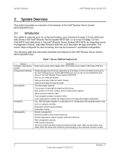
... Overview This section provides an overview of the features of 28 inches (706 mm) Shared storage hard drive bay supporting up to fourteen (14) 2.5-inch SAS hard drives in the Intel® Modular Server System MFSYS25 and up to six hot-swap 3.5-inch SAS/SATA hard disk drives in a...parts to six (6) 3.5-inch SAS/SATA hard drives in a redundant (3+1) configuration with a height of 6U (10.5 inches) and a depth of the Intel® Modular Server System MFSYS25/MFSYS35. 2.1 Introduction The platform supports up to six compute modules, up to fourteen hot-swap 2.5-inch SAS hard disk drives in the...
... Overview This section provides an overview of the features of 28 inches (706 mm) Shared storage hard drive bay supporting up to fourteen (14) 2.5-inch SAS hard drives in the Intel® Modular Server System MFSYS25 and up to six hot-swap 3.5-inch SAS/SATA hard disk drives in a...parts to six (6) 3.5-inch SAS/SATA hard drives in a redundant (3+1) configuration with a height of 6U (10.5 inches) and a depth of the Intel® Modular Server System MFSYS25/MFSYS35. 2.1 Introduction The platform supports up to six compute modules, up to fourteen hot-swap 2.5-inch SAS hard disk drives in the...
Technical Product Specification
Page 13
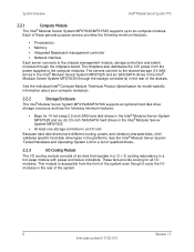
... system even though it cools the I /O modules. These fans provide cooling for model-specific information about your compute module(s). 2.2.2 Storage Enclosure The Intel® Modular Server System MFSYS25/MFSYS35 supports an optional hard disk drive storage enclosure and has the following minimum features: ƒ Processor(s) ƒ Memory ƒ Integrated Baseboard management controller...
... system even though it cools the I /O modules. These fans provide cooling for model-specific information about your compute module(s). 2.2.2 Storage Enclosure The Intel® Modular Server System MFSYS25/MFSYS35 supports an optional hard disk drive storage enclosure and has the following minimum features: ƒ Processor(s) ƒ Memory ƒ Integrated Baseboard management controller...
Technical Product Specification
Page 15
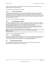
...that allows for a description of the entire Intel® Modular Server System MFSYS25/MFSYS35. System Overview Intel® Modular Server System TPS switch module is the minimum configuration for Intel® Modular Server System MFSYS25V2 only. Note: The chassis management module ...a description of this module. 2.3.2.2 Storage Controller Module The chassis can accommodate up to two hot-swap storage controller modules to support the external hard disks in a (1+1) cooling redundancy. See Section 3.6 for configuration and management of this system. 2.3.3 Chassis Management...
...that allows for a description of the entire Intel® Modular Server System MFSYS25/MFSYS35. System Overview Intel® Modular Server System TPS switch module is the minimum configuration for Intel® Modular Server System MFSYS25V2 only. Note: The chassis management module ...a description of this module. 2.3.2.2 Storage Controller Module The chassis can accommodate up to two hot-swap storage controller modules to support the external hard disks in a (1+1) cooling redundancy. See Section 3.6 for configuration and management of this system. 2.3.3 Chassis Management...
Technical Product Specification
Page 18
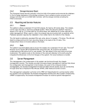
...compute module manageability, the chassis management module provides remote access (such as between the chassis management module and other system components). The Intel® Modular Server System MFSYS25/MFSYS35 uses fixed rails. This module provides a browser-based management interface that allows the configuration and.... Pedestal operation requires the installation of six rubber feet to the hot-swap backplane in the storage enclosure. The 6U height is supported by standard EIA rack units, where 1U equals 1.75 inches. The chassis can be rack-mounted or used in a rack, ...
...compute module manageability, the chassis management module provides remote access (such as between the chassis management module and other system components). The Intel® Modular Server System MFSYS25/MFSYS35 uses fixed rails. This module provides a browser-based management interface that allows the configuration and.... Pedestal operation requires the installation of six rubber feet to the hot-swap backplane in the storage enclosure. The 6U height is supported by standard EIA rack units, where 1U equals 1.75 inches. The chassis can be rack-mounted or used in a rack, ...
Technical Product Specification
Page 20
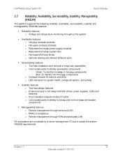
... LAN All subsystems are connected by a server management I2C bus to identify serviceable components - Revision 1.7 13 Intel order number E15155-010 Intel® Modular Server System TPS System Overview 2.7 Reliability, Availability, Serviceability, Usability, Manageability (RASUM) The platform supports the following reliability, availability, serviceability, usability and manageability (RASUM) features: ƒ Reliability features o Voltage and...
... LAN All subsystems are connected by a server management I2C bus to identify serviceable components - Revision 1.7 13 Intel order number E15155-010 Intel® Modular Server System TPS System Overview 2.7 Reliability, Availability, Serviceability, Usability, Manageability (RASUM) The platform supports the following reliability, availability, serviceability, usability and manageability (RASUM) features: ƒ Reliability features o Voltage and...
Technical Product Specification
Page 26
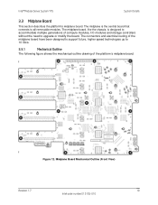
...'s midplane board. Figure 12. Midplane Board Mechanical Outline (Front View) Revision 1.7 19 Intel order number E15155-010 Intel® Modular Server System TPS System Details 3.3 Midplane Board This section describes the platform's... midplane board. The midplane board, like the chassis, is the central board that connects to 10 Gb/s. 3.3.1 Mechanical Outline The following figure shows the mechanical outline drawing of the midplane board have been designed to support...
...'s midplane board. Figure 12. Midplane Board Mechanical Outline (Front View) Revision 1.7 19 Intel order number E15155-010 Intel® Modular Server System TPS System Details 3.3 Midplane Board This section describes the platform's... midplane board. The midplane board, like the chassis, is the central board that connects to 10 Gb/s. 3.3.1 Mechanical Outline The following figure shows the mechanical outline drawing of the midplane board have been designed to support...

Technical Product Specification
Page 39
... for internal needs, and also supplies the disk drive power (12 V boost may be present on the Interposer includes a temperature sensor. Supported drive types include 15K RPM SAS drives. An expander sourced I²C bus is configured as serial and version numbers for 2.5-inch configurations). ...of 4-4-2-2-2 (for the Interposer. Three power supply modules are provided for single-color status LEDs for optional hot-swap disk drives. System Details Intel® Modular Server System TPS 12 V bulk power is a 1000-W DC output supply with 110-240V AC input. The VPD SEEPROM contains ...
... for internal needs, and also supplies the disk drive power (12 V boost may be present on the Interposer includes a temperature sensor. Supported drive types include 15K RPM SAS drives. An expander sourced I²C bus is configured as serial and version numbers for 2.5-inch configurations). ...of 4-4-2-2-2 (for the Interposer. Three power supply modules are provided for single-color status LEDs for optional hot-swap disk drives. System Details Intel® Modular Server System TPS 12 V bulk power is a 1000-W DC output supply with 110-240V AC input. The VPD SEEPROM contains ...

Technical Product Specification
Page 2
... or incompatibilities arising from published specifications. Updated Updated Updated Updated Updated Updated supported memory configurations Disclaimers Information in this document is granted by this document. Intel may make changes to them. Intel Corporation server baseboards support peripheral components and contain a number of Intel Corporation. *Other brands and names may cause the product to deviate from...
... or incompatibilities arising from published specifications. Updated Updated Updated Updated Updated Updated supported memory configurations Disclaimers Information in this document is granted by this document. Intel may make changes to them. Intel Corporation server baseboards support peripheral components and contain a number of Intel Corporation. *Other brands and names may cause the product to deviate from...

Technical Product Specification
Page 3
... of Contents Table of Contents 1. Functional Architecture ...6 3.1 Intel® 5000P Memory Controller Hub (MCH 7 3.1.1 System Bus Interface 7 3.1.2 Processor Support 7 3.1.3 3.2 Memory Subsystem 8 Intel® 6321ESB I/O Controller Hub 16 3.2.1 PCI Subsystem ...16 3.2.2 Serial ATA Support 17 3.2.3 Parallel ATA (PATA) Support 17 3.2.4 USB 2.0 Support...18 3.3 Video Support ...18 3.4 3.4.1 Network Interface Controller (NIC 19 Intel® I/O Acceleration Technology 19 3.4.2 MAC Address Definition...
... of Contents Table of Contents 1. Functional Architecture ...6 3.1 Intel® 5000P Memory Controller Hub (MCH 7 3.1.1 System Bus Interface 7 3.1.2 Processor Support 7 3.1.3 3.2 Memory Subsystem 8 Intel® 6321ESB I/O Controller Hub 16 3.2.1 PCI Subsystem ...16 3.2.2 Serial ATA Support 17 3.2.3 Parallel ATA (PATA) Support 17 3.2.4 USB 2.0 Support...18 3.3 Video Support ...18 3.4 3.4.1 Network Interface Controller (NIC 19 Intel® I/O Acceleration Technology 19 3.4.2 MAC Address Definition...

Technical Product Specification
Page 4
... Appendix A: Integration and Usage Tips 30 Appendix B: BMC Sensor Tables...31 Appendix C: POST Error Messages and Handling 37 Appendix D: Supported Intel® Modular Server System 40 Glossary ...41 Reference Documents ...44 iv Revision 1.4 Intel order number: E15154-007 Jumper Block Settings ...26 5.1 Recovery Jumper Blocks 26 5.1.1 CMOS Clear and Password Reset Usage Procedure...
... Appendix A: Integration and Usage Tips 30 Appendix B: BMC Sensor Tables...31 Appendix C: POST Error Messages and Handling 37 Appendix D: Supported Intel® Modular Server System 40 Glossary ...41 Reference Documents ...44 iv Revision 1.4 Intel order number: E15154-007 Jumper Block Settings ...26 5.1 Recovery Jumper Blocks 26 5.1.1 CMOS Clear and Password Reset Usage Procedure...

Technical Product Specification
Page 7
...-level architecture of their specific application and environmental conditions. Integration and Usage Tips ƒ Appendix B - Revision 1.4 1 Intel order number: E15154-007 Product Regulatory Requirements ƒ Appendix A - Supported Intel® Modular Server System 1.2 Intel® Compute Module Use Disclaimer Intel® Modular Server components require adequate airflow to determine the amount of various board subsystems, including...
...-level architecture of their specific application and environmental conditions. Integration and Usage Tips ƒ Appendix B - Revision 1.4 1 Intel order number: E15154-007 Product Regulatory Requirements ƒ Appendix A - Supported Intel® Modular Server System 1.2 Intel® Compute Module Use Disclaimer Intel® Modular Server components require adequate airflow to determine the amount of various board subsystems, including...

Technical Product Specification
Page 8
...131; Two USB 2.0 ports ƒ Video connector Internal connectors/headers: ƒ One DH-10 Serial A debug header ƒ One Intel® I/O Mezzanine Connector supporting Dual Gigabit NIC Intel® I/O Expansion Module (Optional) ATI* ES1000 video controller with system bus speeds of 1066 MHz or 1333 MHz 8 keyed DIMM ...Chipset On-board Connectors/Headers On-board Video On-board Hard Drive Controller LAN Description 771-pin LGA sockets supporting one or two Dual-Core or Quad-Core Intel® Xeon® processors 5000 sequence, with 16MB DDR SDRAM LSI* 1064e SAS controller Two integrated ...
...131; Two USB 2.0 ports ƒ Video connector Internal connectors/headers: ƒ One DH-10 Serial A debug header ƒ One Intel® I/O Mezzanine Connector supporting Dual Gigabit NIC Intel® I/O Expansion Module (Optional) ATI* ES1000 video controller with system bus speeds of 1066 MHz or 1333 MHz 8 keyed DIMM ...Chipset On-board Connectors/Headers On-board Video On-board Hard Drive Controller LAN Description 771-pin LGA sockets supporting one or two Dual-Core or Quad-Core Intel® Xeon® processors 5000 sequence, with 16MB DDR SDRAM LSI* 1064e SAS controller Two integrated ...

Technical Product Specification
Page 12
...designed for MCH components supported on the Intel® 5000 Chipset Family. Compute Module Functional Block Diagram Note: The previous diagram uses the Intel® 5000P MCH as a general reference designator for systems based on the Dual-Core and Quad-Core Intel® Xeon®... processor 5000 sequence with each of the functional architecture blocks, see the Intel® 5000 Series Chipsets Server Board Family Datasheet. 2BFunctional Architecture Intel® Compute Module MFS5000SI TPS 3. Figure 4. This...
...designed for MCH components supported on the Intel® 5000 Chipset Family. Compute Module Functional Block Diagram Note: The previous diagram uses the Intel® 5000P MCH as a general reference designator for systems based on the Dual-Core and Quad-Core Intel® Xeon®... processor 5000 sequence with each of the functional architecture blocks, see the Intel® 5000 Series Chipsets Server Board Family Datasheet. 2BFunctional Architecture Intel® Compute Module MFS5000SI TPS 3. Figure 4. This...

Technical Product Specification
Page 13
... terminator is implemented on each bus. 3.1.2 Processor Support The Intel® Compute Module MFS5000SI supports one processor is supported in the Intel® Compute Module MFS5000SI. Intel® Compute Module MFS5000SI TPS 2BFunctional Architecture 3.1 Intel® 5000P Memory Controller Hub (MCH) This ...refer to 115 A of transferring data at up to http://support.intel.com/support/motherboards/server/MFS5000SI/ and select the Supported Processors List. 3.1.2.1 Processor Population Rules When two processors are not supported in N and N-1 configurations only. To see a list...
... terminator is implemented on each bus. 3.1.2 Processor Support The Intel® Compute Module MFS5000SI supports one processor is supported in the Intel® Compute Module MFS5000SI. Intel® Compute Module MFS5000SI TPS 2BFunctional Architecture 3.1 Intel® 5000P Memory Controller Hub (MCH) This ...refer to 115 A of transferring data at up to http://support.intel.com/support/motherboards/server/MFS5000SI/ and select the Supported Processors List. 3.1.2.1 Processor Population Rules When two processors are not supported in N and N-1 configurations only. To see a list...

Technical Product Specification
Page 14
...four FBD channels are organized into two branches of two channels per branch. 2BFunctional Architecture Intel® Compute Module MFS5000SI TPS 3.1.2.2 Common Enabling Kit (CEK) Design Support The compute module complies with a CEK spring snapped onto the underside of the server... the processor and the thermal interface material (TIM). FBD memory channels are organized into two branches for RAID 1 (mirroring) support. 8 Revision 1.4 Intel order number: E15154-007 The actual processor heatsink and CEK solutions compatible with DDR2-667. FBD memory utilizes a narrow highspeed ...
...four FBD channels are organized into two branches of two channels per branch. 2BFunctional Architecture Intel® Compute Module MFS5000SI TPS 3.1.2.2 Common Enabling Kit (CEK) Design Support The compute module complies with a CEK spring snapped onto the underside of the server... the processor and the thermal interface material (TIM). FBD memory channels are organized into two branches for RAID 1 (mirroring) support. 8 Revision 1.4 Intel order number: E15154-007 The actual processor heatsink and CEK solutions compatible with DDR2-667. FBD memory utilizes a narrow highspeed ...

Technical Product Specification
Page 15
... B2 DIMM C1 DIMM C2 DIMM D1 DIMM D2 Address 0xA0 0xA2 0xA0 0xA2 0xA0 0xA2 0xA0 0xA2 3.1.3.1 Memory RASUM Features1 The MCH supports several memory RASUM (Reliability, Availability, Serviceability, Usability, and Manageability) features. Table 1. I2C Addresses for each DIMM slot. For more ...Retry on the server board uses a dedicated I2C bus to retrieve DIMM information needed to program the MCH memory registers. Revision 1.4 9 Intel order number: E15154-007 Memory Layout To boot the system, the system BIOS on Correctable Errors, Memory Built In Self Test, DIMM Sparing...
... B2 DIMM C1 DIMM C2 DIMM D1 DIMM D2 Address 0xA0 0xA2 0xA0 0xA2 0xA0 0xA2 0xA0 0xA2 3.1.3.1 Memory RASUM Features1 The MCH supports several memory RASUM (Reliability, Availability, Serviceability, Usability, and Manageability) features. Table 1. I2C Addresses for each DIMM slot. For more ...Retry on the server board uses a dedicated I2C bus to retrieve DIMM information needed to program the MCH memory registers. Revision 1.4 9 Intel order number: E15154-007 Memory Layout To boot the system, the system BIOS on Correctable Errors, Memory Built In Self Test, DIMM Sparing...

Technical Product Specification
Page 16
...and B1, C1 and D1, A2 and B2, C2 and D2. Mixing memory vendors is not validated and is recommended. Intel supported DIMM configurations for the Intel® Compute Module MFS5000SI, refer to size, speed, and organization. Mixing memory type, size, speed, and/or rank ...Mode 2 GB 4 GB 8 GB 16 GB Table 3. DDR2-533 memory is not supported. 2BFunctional Architecture Intel® Compute Module MFS5000SI TPS 3.1.3.2 Supported and Nonsupported Memory Configurations The server board design supports up to be validated on this product. x4 Dual Rank DRAM Technology x4 Dual Rank ...
...and B1, C1 and D1, A2 and B2, C2 and D2. Mixing memory vendors is not validated and is recommended. Intel supported DIMM configurations for the Intel® Compute Module MFS5000SI, refer to size, speed, and organization. Mixing memory type, size, speed, and/or rank ...Mode 2 GB 4 GB 8 GB 16 GB Table 3. DDR2-533 memory is not supported. 2BFunctional Architecture Intel® Compute Module MFS5000SI TPS 3.1.3.2 Supported and Nonsupported Memory Configurations The server board design supports up to be validated on this product. x4 Dual Rank DRAM Technology x4 Dual Rank ...

Technical Product Specification
Page 17
..., and D1. The following diagram shows the recommended minimum DIMM memory configuration. Refer to section 3.1.3.2 for system performance reasons, Intel's recommendation is that configuration supports Memory Sparing. Intel® Compute Module MFS5000SI TPS 2BFunctional Architecture Supported and Validated configuration : Slot is populated Supported but not validated configuration : Slot is populated Slot is only tested and...
..., and D1. The following diagram shows the recommended minimum DIMM memory configuration. Refer to section 3.1.3.2 for system performance reasons, Intel's recommendation is that configuration supports Memory Sparing. Intel® Compute Module MFS5000SI TPS 2BFunctional Architecture Supported and Validated configuration : Slot is populated Supported but not validated configuration : Slot is populated Slot is only tested and...

Technical Product Specification
Page 18
..., speed, and organization. Recommended Minimum Two-DIMM Memory Configuration Note: The server board supports single DIMM mode operation. 2BFunctional Architecture Intel® Compute Module MFS5000SI TPS Channel B Channel A Channel C Channel D MCH Branch 0 DIMDMIMDAMIM1DAMIM2DBMIM1DBMIM2DCMIM1DCMIM2DM1D2 Branch 1 TP02300 Figure 7. Intel only validates and supports this configuration with respect to the configuration shown in the following diagram. The...
..., speed, and organization. Recommended Minimum Two-DIMM Memory Configuration Note: The server board supports single DIMM mode operation. 2BFunctional Architecture Intel® Compute Module MFS5000SI TPS Channel B Channel A Channel C Channel D MCH Branch 0 DIMDMIMDAMIM1DAMIM2DBMIM1DBMIM2DCMIM1DCMIM2DM1D2 Branch 1 TP02300 Figure 7. Intel only validates and supports this configuration with respect to the configuration shown in the following diagram. The...