

Technical Product Specification
Page 4
...Compatibility Notices 41 4.4.1 FCC Verification Statement (USA 41 4.4.2 ICES-003 (Canada 42 4.4.3 Europe (CE Declaration of Contents Intel® Modular Server System TPS 3.5.4 Drawings...26 3.5.5 Architectural Overview 26 3.6 Ethernet Switch Module 27 3.6.1 Introduction ...27 3.6.2 Mechanical Outline 28 3.6.3 Block Diagram ...29 3.6.4 Architectural Overview 29 3.7 Storage Controller Module... Compliance - Table of Conformity 42 4.4.4 VCCI (Japan) ...43 4.4.5 BSMI (Taiwan) ...43 Glossary...45 Reference Documents ...48 iv Revision 1.7 Intel order number E15155-010
...Compatibility Notices 41 4.4.1 FCC Verification Statement (USA 41 4.4.2 ICES-003 (Canada 42 4.4.3 Europe (CE Declaration of Contents Intel® Modular Server System TPS 3.5.4 Drawings...26 3.5.5 Architectural Overview 26 3.6 Ethernet Switch Module 27 3.6.1 Introduction ...27 3.6.2 Mechanical Outline 28 3.6.3 Block Diagram ...29 3.6.4 Architectural Overview 29 3.7 Storage Controller Module... Compliance - Table of Conformity 42 4.4.4 VCCI (Japan) ...43 4.4.5 BSMI (Taiwan) ...43 Glossary...45 Reference Documents ...48 iv Revision 1.7 Intel order number E15155-010
Technical Product Specification
Page 5
... Management Module Block Diagram 25 Figure 18. Ethernet Switch Module Mechanical Outline (Top View 28 Figure 21. View of Intel® Modular Server System MFSYS25 System Board Connectivity 9 Figure 6. Front View of Empty Intel® Modular Server System MFSYS25 18 Figure 11....Platform 5 Figure 4. Front View of Storage Controller Module 31 Revision 1.7 v Intel order number E15155-010 Ethernet Switch Module Block Diagram 29 Figure 22. Mechanical Outline of Figures Figure 1. Intel® Modular Server System TPS List of Figures List of Storage Controller Module ...
... Management Module Block Diagram 25 Figure 18. Ethernet Switch Module Mechanical Outline (Top View 28 Figure 21. View of Intel® Modular Server System MFSYS25 System Board Connectivity 9 Figure 6. Front View of Empty Intel® Modular Server System MFSYS25 18 Figure 11....Platform 5 Figure 4. Front View of Storage Controller Module 31 Revision 1.7 v Intel order number E15155-010 Ethernet Switch Module Block Diagram 29 Figure 22. Mechanical Outline of Figures Figure 1. Intel® Modular Server System TPS List of Figures List of Storage Controller Module ...
Technical Product Specification
Page 9
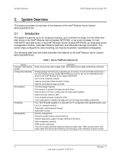
...hot-swap power supplies. Rear access to optional hot-swap hard disk drives. Front viewable compute module ID LEDs. Optional secondary Ethernet switch module. Color-coded parts to six hot-swap 3.5-inch SAS/SATA hard disk drives in a redundant (3+1) configuration with a height ... the individual compute module. 2 Revision 1.7 Intel order number E15155-010 Tool-less design features. Four 1000-W power supplies in the Intel® Modular Server System MFSYS35, an integrated server management module, redundant Ethernet switches, and redundant storage controllers. Redundant cooling.
...hot-swap power supplies. Rear access to optional hot-swap hard disk drives. Front viewable compute module ID LEDs. Optional secondary Ethernet switch module. Color-coded parts to six hot-swap 3.5-inch SAS/SATA hard disk drives in a redundant (3+1) configuration with a height ... the individual compute module. 2 Revision 1.7 Intel order number E15155-010 Tool-less design features. Four 1000-W power supplies in the Intel® Modular Server System MFSYS35, an integrated server management module, redundant Ethernet switches, and redundant storage controllers. Redundant cooling.
Technical Product Specification
Page 13
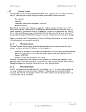
.... Each of the chassis. This module is accessible from the power supplies to the chassis management module, storage controllers and switch modules through the storage controller(s) in the rear of these general-purpose servers provides the following minimum features: ƒ Bays...storage controller in an I/O slot Because hard disk drives have different cooling, power, and vibration characteristics, Intel validates specific hard disk drive types in the platforms. See the Intel® Modular Server System Tested Hardware and Operating System List for all I /O cooling module consists of ...
.... Each of the chassis. This module is accessible from the power supplies to the chassis management module, storage controllers and switch modules through the storage controller(s) in the rear of these general-purpose servers provides the following minimum features: ƒ Bays...storage controller in an I/O slot Because hard disk drives have different cooling, power, and vibration characteristics, Intel validates specific hard disk drive types in the platforms. See the Intel® Modular Server System Tested Hardware and Operating System List for all I /O cooling module consists of ...
Technical Product Specification
Page 14
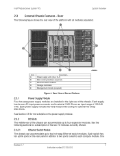
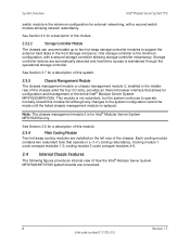
...on the rear panel in the right rear of 100-240 VAC. Each switch has ten uplink ports on the power supply module. 2.3.2 I /O modules currently offered. 2.3.2.1 Ethernet Switch Module The chassis can accommodate up to four expansion modules. See the following... figure shows the rear view of the chassis can accommodate up to two hot-swap Ethernet switch modules. One Revision 1.7 7 Intel order number E15155-010 Intel® Modular Server System...
...on the rear panel in the right rear of 100-240 VAC. Each switch has ten uplink ports on the power supply module. 2.3.2 I /O modules currently offered. 2.3.2.1 Ethernet Switch Module The chassis can accommodate up to four expansion modules. See the following... figure shows the rear view of the chassis can accommodate up to two hot-swap Ethernet switch modules. One Revision 1.7 7 Intel order number E15155-010 Intel® Modular Server System...
Technical Product Specification
Page 15
... contains two redundant fans that allows for a description of the chassis. Cooling module 1 cools compute modules 1-3; System Overview Intel® Modular Server System TPS switch module is the minimum configuration for Intel® Modular Server System MFSYS25V2 only. cooling module 2 cools compute modules 4-6. 2.4 Internal Chassis Features The following figures provide an internal view of...
... contains two redundant fans that allows for a description of the chassis. Cooling module 1 cools compute modules 1-3; System Overview Intel® Modular Server System TPS switch module is the minimum configuration for Intel® Modular Server System MFSYS25V2 only. cooling module 2 cools compute modules 4-6. 2.4 Internal Chassis Features The following figures provide an internal view of...
Technical Product Specification
Page 16
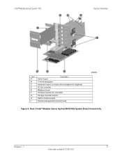
View of Intel® Modular Server System MFSYS25 System Board Connectivity Revision 1.7 9 Intel order number E15155-010 Intel® Modular Server System TPS System Overview Item A B C D E F G H I Server board Description 14-drive backplane Interposer board (connects drive backplane to midplane) I/O fan controller Midplane board Compute module fan controllers Storage controller boards Switch module boards Chassis management module board Figure 5.
View of Intel® Modular Server System MFSYS25 System Board Connectivity Revision 1.7 9 Intel order number E15155-010 Intel® Modular Server System TPS System Overview Item A B C D E F G H I Server board Description 14-drive backplane Interposer board (connects drive backplane to midplane) I/O fan controller Midplane board Compute module fan controllers Storage controller boards Switch module boards Chassis management module board Figure 5.

Technical Product Specification
Page 17
... system and provides power and I /O fan controller Midplane board Compute module fan controllers Storage controller boards Switch module boards Chassis management module board Figure 6. This board is considered to all chassis subassemblies and options. System Overview Intel® Modular Server System TPS Item A B C D E F G H I Server board Description 6-drive backplane Interposer board (connects drive...
... system and provides power and I /O fan controller Midplane board Compute module fan controllers Storage controller boards Switch module boards Chassis management module board Figure 6. This board is considered to all chassis subassemblies and options. System Overview Intel® Modular Server System TPS Item A B C D E F G H I Server board Description 6-drive backplane Interposer board (connects drive...

Technical Product Specification
Page 19
...that runs Linux to the module, including power control, reset, sensor reading, remote KVM, remote media and remote serial console. System Overview Intel® Modular Server System TPS HDD Backplane I2C BUSSES 10/100Mbps Ethernet Clear Bay: Chassis Management Connections I2C BUS 10/100Mbps Ethernet SPI BUS... PSU PSU STORAGE SWITCH I2C BUS_0 I2C BUS_0 I2C BUS_2 I2C BUS_2 I2C BUS MANAGEMENT 10/100 Ethernet SWITCH 7 Busses 5 Used w/ SMB SPI Bus I2C BUS_2 STORAGE I2C BUS_2 I2C BUS_1 I2C BUS_1 ...
...that runs Linux to the module, including power control, reset, sensor reading, remote KVM, remote media and remote serial console. System Overview Intel® Modular Server System TPS HDD Backplane I2C BUSSES 10/100Mbps Ethernet Clear Bay: Chassis Management Connections I2C BUS 10/100Mbps Ethernet SPI BUS... PSU PSU STORAGE SWITCH I2C BUS_0 I2C BUS_0 I2C BUS_2 I2C BUS_2 I2C BUS MANAGEMENT 10/100 Ethernet SWITCH 7 Busses 5 Used w/ SMB SPI Bus I2C BUS_2 STORAGE I2C BUS_2 I2C BUS_1 I2C BUS_1 ...
Technical Product Specification
Page 20
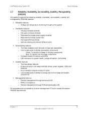
... ƒ Usability features o Tool-less design features o External access to hot-swap hard disk drives, power supplies, LEDs and switches o Front viewable compute module ID LEDs o Color-coded parts to identify hot-swap and non-hot-swap serviceable components ƒ...KVM and dedicated LAN All subsystems are connected by a server management I2C bus to identify serviceable components - Revision 1.7 13 Intel order number E15155-010 Intel® Modular Server System TPS System Overview 2.7 Reliability, Availability, Serviceability, Usability, Manageability (RASUM) The platform supports the ...
... ƒ Usability features o Tool-less design features o External access to hot-swap hard disk drives, power supplies, LEDs and switches o Front viewable compute module ID LEDs o Color-coded parts to identify hot-swap and non-hot-swap serviceable components ƒ...KVM and dedicated LAN All subsystems are connected by a server management I2C bus to identify serviceable components - Revision 1.7 13 Intel order number E15155-010 Intel® Modular Server System TPS System Overview 2.7 Reliability, Availability, Serviceability, Usability, Manageability (RASUM) The platform supports the ...

Technical Product Specification
Page 22
...Specifications Summary The following table provides a summary of the power and heat dissipation specifications for all modules in the Intel® Modular Server System MFSYS25/MFSYS35. Table 6. Power and Heat Dissipation Specifications of the 12V power budget for the... Intel® Modular Server System MFSYS25/MFSYS35. Physical Dimensions of Hardware Components Module Chassis Compute module CMM I/O Storage Hard drive bay Power supply module Main cooling module I /O Switch Storage module 2.5/3.5-inch SAS drives Chassis Power supply...
...Specifications Summary The following table provides a summary of the power and heat dissipation specifications for all modules in the Intel® Modular Server System MFSYS25/MFSYS35. Table 6. Power and Heat Dissipation Specifications of the 12V power budget for the... Intel® Modular Server System MFSYS25/MFSYS35. Physical Dimensions of Hardware Components Module Chassis Compute module CMM I/O Storage Hard drive bay Power supply module Main cooling module I /O Switch Storage module 2.5/3.5-inch SAS drives Chassis Power supply...
Technical Product Specification
Page 29
... with all system components either through the I2C bus or through the Intel® Ethernet Switch Module. (The CMM2 connects through the Ethernet directly to the storage controller module(s) and the Intel® Ethernet Switch Module(s), and indirectly to the built-in server control GUI, and...with all system components either through the I2C bus or through the Intel® Ethernet Switch Module. (The CMM connects through the Ethernet directly to the storage controller module(s) and the Intel® Ethernet Switch Module(s), and indirectly to the built-in addition to the compute ...
... with all system components either through the I2C bus or through the Intel® Ethernet Switch Module. (The CMM2 connects through the Ethernet directly to the storage controller module(s) and the Intel® Ethernet Switch Module(s), and indirectly to the built-in server control GUI, and...with all system components either through the I2C bus or through the Intel® Ethernet Switch Module. (The CMM connects through the Ethernet directly to the storage controller module(s) and the Intel® Ethernet Switch Module(s), and indirectly to the built-in addition to the compute ...
Technical Product Specification
Page 34
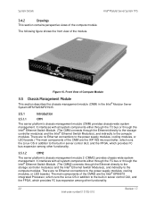
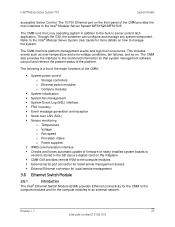
... GUI, the customer can poll and retrieve the present status of the CMM: ƒ System power control o Storage controllers o Ethernet switch modules o Compute modules ƒ System initialization ƒ System fan management ƒ System Event Log (SEL) interface ƒ FRU inventory... serial port connector for local/remote management access ƒ External Ethernet connector for local/remote management 3.6 Ethernet Switch Module 3.6.1 Introduction The Intel® Ethernet Switch Module (ESM) provides Ethernet connectivity for the CMM to the compute modules and for the compute modules to...
... GUI, the customer can poll and retrieve the present status of the CMM: ƒ System power control o Storage controllers o Ethernet switch modules o Compute modules ƒ System initialization ƒ System fan management ƒ System Event Log (SEL) interface ƒ FRU inventory... serial port connector for local/remote management access ƒ External Ethernet connector for local/remote management 3.6 Ethernet Switch Module 3.6.1 Introduction The Intel® Ethernet Switch Module (ESM) provides Ethernet connectivity for the CMM to the compute modules and for the compute modules to...
Technical Product Specification
Page 36
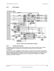
... CMM, and one I²C interface to the CMM (for the CMM to -point links across the midplane. Revision 1.7 29 Intel order number E15155-010 Ethernet Switch Module Block Diagram 3.6.4 Architectural Overview The ESM provides networking and switch functions to the compute modules. Intel® Modular Server System TPS 3.6.3 Block Diagram System Details Figure 21.
... CMM, and one I²C interface to the CMM (for the CMM to -point links across the midplane. Revision 1.7 29 Intel order number E15155-010 Ethernet Switch Module Block Diagram 3.6.4 Architectural Overview The ESM provides networking and switch functions to the compute modules. Intel® Modular Server System TPS 3.6.3 Block Diagram System Details Figure 21.

Technical Product Specification
Page 39
The VPD SEEPROM contains a WW (World Wide) unique address which includes six compute modules, two storage controllers, two Ethernet switch modules, one chassis management module, and fourteen hot-swap 2.5-inch hard disk drives or six hot-swap 3.5-inch hard disk drives...Interposer has a power converter function for optional hot-swap disk drives. The power subsystem receives AC power through expander SES pages. System Details Intel® Modular Server System TPS 12 V bulk power is connected to the drive backplane IDROM. Three power supply modules are provided for single-...
The VPD SEEPROM contains a WW (World Wide) unique address which includes six compute modules, two storage controllers, two Ethernet switch modules, one chassis management module, and fourteen hot-swap 2.5-inch hard disk drives or six hot-swap 3.5-inch hard disk drives...Interposer has a power converter function for optional hot-swap disk drives. The power subsystem receives AC power through expander SES pages. System Details Intel® Modular Server System TPS 12 V bulk power is connected to the drive backplane IDROM. Three power supply modules are provided for single-...

Technical Product Specification
Page 52
... Programmable Read-Only Memory Electromagnetic Compatibility Electromagnetic Interference Emergency Management Port External Product Specification Electrostatic Discharge Ethernet Switch Module Federal Communications Commission Field-Programmable Gate Array Fault Resilient Booting Field Replaceable Unit Front Side Bus ...Intelligent Chassis Management Bus Integrated Device Electronics International Electrotechnical Commission Revision 1.7 45 Intel order number E15155-010 Intel® Modular Server System TPS Glossary Glossary This appendix contains important terms used in the preceding...
... Programmable Read-Only Memory Electromagnetic Compatibility Electromagnetic Interference Emergency Management Port External Product Specification Electrostatic Discharge Ethernet Switch Module Federal Communications Commission Field-Programmable Gate Array Fault Resilient Booting Field Replaceable Unit Front Side Bus ...Intelligent Chassis Management Bus Integrated Device Electronics International Electrotechnical Commission Revision 1.7 45 Intel order number E15155-010 Intel® Modular Server System TPS Glossary Glossary This appendix contains important terms used in the preceding...
Technical Product Specification
Page 53
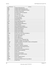
Glossary Intel® Modular Server System TPS Word/Acronym IMB IPMB IPMI ISP ITE ITP JTAG KVM LAN LED LPC LVDS NIC OEM OS OTP PCI PDB ... Motherboard Revolutions Per Minute Restriction of Hazardous Substances SCSI Accessed Fault-Tolerant Enclosure Serial Attached SCSI Serial Advanced Technology Attachment Single Connector Attachment Serial Clock Switch Controller Module Small Computer Systems Interface Serial Data System Diagnostic Interrupt Sensor Data Record Synchronous Dynamic Random Access Memory Single-Ended 46 Revision...
Glossary Intel® Modular Server System TPS Word/Acronym IMB IPMB IPMI ISP ITE ITP JTAG KVM LAN LED LPC LVDS NIC OEM OS OTP PCI PDB ... Motherboard Revolutions Per Minute Restriction of Hazardous Substances SCSI Accessed Fault-Tolerant Enclosure Serial Attached SCSI Serial Advanced Technology Attachment Single Connector Attachment Serial Clock Switch Controller Module Small Computer Systems Interface Serial Data System Diagnostic Interrupt Sensor Data Record Synchronous Dynamic Random Access Memory Single-Ended 46 Revision...

Technical Product Specification
Page 25
...Transceiver (PHY). This chip contains all of the necessary circuitry to support the following table. These interfaces are assigned to it at the Intel factory. Intel® I/OAT provides safe and flexible network acceleration through more efficiently through an internal DH-10 serial header (J1B1) to NIC 1 ... the built-in Dual GbE MAC features of the board. Intel® I /O support is provided by the Integrated BMC's embedded network stack to enable IPMI remote management over the midplane board to the Ethernet switch module in the rear of third-party network stacks and preserving...
...Transceiver (PHY). This chip contains all of the necessary circuitry to support the following table. These interfaces are assigned to it at the Intel factory. Intel® I/OAT provides safe and flexible network acceleration through more efficiently through an internal DH-10 serial header (J1B1) to NIC 1 ... the built-in Dual GbE MAC features of the board. Intel® I /O support is provided by the Integrated BMC's embedded network stack to enable IPMI remote management over the midplane board to the Ethernet switch module in the rear of third-party network stacks and preserving...

Technical Product Specification
Page 10
...1 with Heatsink E Mezzanine Card Connector 2 F Midplane Power Connector G Midplane Signal Connector H Midplane Guide Pin Receptacle I /O components for the Intel® Compute Module MFS5520VI. Component and Connector Location Diagram 2.2.2 External I/O Connector Locations The following figure shows the board layout of the external I... CPU 1 DIMM Slots J CPU 2 Socket K Power/Fault LEDs L Power Switch M Activity and ID LEDs N Video Connector O USB Ports 2 and 3 P USB1 Ports 0 and 1 Q CMOS Battery Figure 1. Each ...
...1 with Heatsink E Mezzanine Card Connector 2 F Midplane Power Connector G Midplane Signal Connector H Midplane Guide Pin Receptacle I /O components for the Intel® Compute Module MFS5520VI. Component and Connector Location Diagram 2.2.2 External I/O Connector Locations The following figure shows the board layout of the external I... CPU 1 DIMM Slots J CPU 2 Socket K Power/Fault LEDs L Power Switch M Activity and ID LEDs N Video Connector O USB Ports 2 and 3 P USB1 Ports 0 and 1 Q CMOS Battery Figure 1. Each ...

Technical Product Specification
Page 23
...Channels A/B/C can have a different set of parameters and RAS still functions. ƒ For the Mirrored Channel mode, the memory in a switch back to the Independent Channel Mode. If DIMM_D1 and DIMM_E1 are associated with these rules results in Channels A and B of each processor ...processor sockets are populated and the installed DIMMs are not identical, then the system switches to the Independent Channel mode. The system operates in the Independent Channel mode. Functional Architecture Intel® Compute Module MFS5520VI TPS ƒ The memory operational mode is DIMM_A1, DIMM_B1...
...Channels A/B/C can have a different set of parameters and RAS still functions. ƒ For the Mirrored Channel mode, the memory in a switch back to the Independent Channel Mode. If DIMM_D1 and DIMM_E1 are associated with these rules results in Channels A and B of each processor ...processor sockets are populated and the installed DIMMs are not identical, then the system switches to the Independent Channel mode. The system operates in the Independent Channel mode. Functional Architecture Intel® Compute Module MFS5520VI TPS ƒ The memory operational mode is DIMM_A1, DIMM_B1...