
Technical Product Specification
Page 34
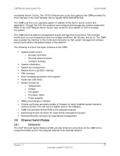
...can poll and retrieve the present status of newly installed system boards to the Intel® Modular Server System MFSYS25/MFSYS35. Refer to the Intel® Modular Server System User Guide for the compute modules to this monitored information so that system management software can ...configure and manage any system component. Revision 1.7 27 Intel order number E15155-010 The CMM also provides...
...can poll and retrieve the present status of newly installed system boards to the Intel® Modular Server System MFSYS25/MFSYS35. Refer to the Intel® Modular Server System User Guide for the compute modules to this monitored information so that system management software can ...configure and manage any system component. Revision 1.7 27 Intel order number E15155-010 The CMM also provides...

Specification Update
Page 8
...graph for Ethernet Mezzanine Card AXXGBIOMEZV...48 88. Power Budget Information Incorrect in it..... 49 Documentation Changes...49 1. Intel® Compute Module MFS5520VI Technical Product Specification has an incorrect statement about Turbo Mode setting 51 VIII Pool Incorrect ...sleep state 47 86. MAC address missing in Intel® Modular Server System MFSYS25 documentation 49 2. MFS5520VI fail to the replacement 46 83. drive. Intel® Modular Server System MFSYS25/MFSYS35 Quick Start User's Guide has an incorrect Package Contents list 51 5. ...
...graph for Ethernet Mezzanine Card AXXGBIOMEZV...48 88. Power Budget Information Incorrect in it..... 49 Documentation Changes...49 1. Intel® Compute Module MFS5520VI Technical Product Specification has an incorrect statement about Turbo Mode setting 51 VIII Pool Incorrect ...sleep state 47 86. MAC address missing in Intel® Modular Server System MFSYS25 documentation 49 2. MFS5520VI fail to the replacement 46 83. drive. Intel® Modular Server System MFSYS25/MFSYS35 Quick Start User's Guide has an incorrect Package Contents list 51 5. ...

Specification Update
Page 20
... Linux 5 Server U1 (32bit and 64bit) is not correct 81. Fixed System Fault LED not depicted in front system views in Intel® Modular Server System MFSYS25 TPS 3. Enterprise Platforms and Services Division Specification Update 79. Fixed Remote KVM mouse mode is always Absolute...Autostart' does not check available memory when starting VMs 82. Fixed Intel® Modular Server System MFSYS25/MFSYS35 Quick Start User's Guide has an incorrect Package Contents list Following are in SMBIOS data for the Intel® Modular Server Systems 84. Fix MAC address missing in -depth...
... Linux 5 Server U1 (32bit and 64bit) is not correct 81. Fixed System Fault LED not depicted in front system views in Intel® Modular Server System MFSYS25 TPS 3. Enterprise Platforms and Services Division Specification Update 79. Fixed Remote KVM mouse mode is always Absolute...Autostart' does not check available memory when starting VMs 82. Fixed Intel® Modular Server System MFSYS25/MFSYS35 Quick Start User's Guide has an incorrect Package Contents list Following are in SMBIOS data for the Intel® Modular Server Systems 84. Fix MAC address missing in -depth...

Specification Update
Page 57
..., in-between the I/O Cooling Module and the server in the bottom slot of the Intel® Modular Server System MFSYS25 in the following documents: -008 MFSYS25 User Guide, -003 MFSYS25 Quick Start User's Guide, and -003 MFSYS25 TPS. Status Fixed Intel Confidential 49 Clarification The System Fault LED is not identified in email address. Status No...
..., in-between the I/O Cooling Module and the server in the bottom slot of the Intel® Modular Server System MFSYS25 in the following documents: -008 MFSYS25 User Guide, -003 MFSYS25 Quick Start User's Guide, and -003 MFSYS25 TPS. Status Fixed Intel Confidential 49 Clarification The System Fault LED is not identified in email address. Status No...

Specification Update
Page 59
... MFSYS25/MFSYS35 Quick Start User's Guide has an incorrect Package Contents list Problem Clarification Status On the front side of either the MFSYS25 or MFSYS35 systems. The rail kit is disabled by default on Intel® Compute Module MFS5520VI. Intel® Compute Module MFS5520VI...be purchased separately. Turbo Mode is not included in the base system configuration or the shipping container of the Intel® Modular Server System MFSYS25/MFSYS35 Quick Start User's Guide, Document #E11186-00X, the Package Contents list incorrectly shows a rail kit included in document #E11186-008....
... MFSYS25/MFSYS35 Quick Start User's Guide has an incorrect Package Contents list Problem Clarification Status On the front side of either the MFSYS25 or MFSYS35 systems. The rail kit is disabled by default on Intel® Compute Module MFS5520VI. Intel® Compute Module MFS5520VI...be purchased separately. Turbo Mode is not included in the base system configuration or the shipping container of the Intel® Modular Server System MFSYS25/MFSYS35 Quick Start User's Guide, Document #E11186-00X, the Package Contents list incorrectly shows a rail kit included in document #E11186-008....

Specification Update
Page 3
... installing an operating system. This includes step-by -step instructions for powering on using the Intel® Modular Server System. Intel® Modular Server System Service Guide iii Chapter 5 provides information to configure the modular server system. Preface About this manual, see...mfsys35. This includes information for adding and replacing components in troubleshooting the Intel® Modular Server System. This includes information on how to use the Intel® Modular Server Control user interface to assist you for adding and replacing components. Chapter 2 provides...
... installing an operating system. This includes step-by -step instructions for powering on using the Intel® Modular Server System. Intel® Modular Server System Service Guide iii Chapter 5 provides information to configure the modular server system. Preface About this manual, see...mfsys35. This includes information for adding and replacing components in troubleshooting the Intel® Modular Server System. This includes information on how to use the Intel® Modular Server Control user interface to assist you for adding and replacing components. Chapter 2 provides...

Specification Update
Page 8
... Bay 46 Removing a 3.5-inch Hard Drive from the Storage Bay 49 Installing and Removing an Intel® Compute Module 52 Installing an Intel® Compute Module 52 Removing an Intel® Compute Module 53 Removing and Installing the 2.5-inch Hard Disk Drive Bay Module 54 Removing... System 67 Installing an Operating System 67 Monitoring the Server System 68 Shutting Down the Server System 68 Using the Intel® Modular Server Control User Interface 69 Introduction ...69 System Configuration Requirements 70 Setting Up a Remote Connection 71 Remote Client System Requirements 72 Log...
... Bay 46 Removing a 3.5-inch Hard Drive from the Storage Bay 49 Installing and Removing an Intel® Compute Module 52 Installing an Intel® Compute Module 52 Removing an Intel® Compute Module 53 Removing and Installing the 2.5-inch Hard Disk Drive Bay Module 54 Removing... System 67 Installing an Operating System 67 Monitoring the Server System 68 Shutting Down the Server System 68 Using the Intel® Modular Server Control User Interface 69 Introduction ...69 System Configuration Requirements 70 Setting Up a Remote Connection 71 Remote Client System Requirements 72 Log...

Specification Update
Page 9
... Simple Network Management Protocol (SNMP 135 User Accounts ...139 LDAP ...139 Event Policies ...140 Notification ...142 Import/Export ...144 Language Option Setting ...144 Feature Activation ...145 Firmware Updates ...146 Restore System Settings ...148 Access Online Help ...150 Log Out from the Intel® Modular Server Control 150 Troubleshooting ...and Certification Information 157 Product Regulatory Compliance 157 Product Regulatory Compliance Markings 159 Regulated Specified Components 165 Electromagnetic Compatibility Notices 166 Intel® Modular Server System Service Guide ix
... Simple Network Management Protocol (SNMP 135 User Accounts ...139 LDAP ...139 Event Policies ...140 Notification ...142 Import/Export ...144 Language Option Setting ...144 Feature Activation ...145 Firmware Updates ...146 Restore System Settings ...148 Access Online Help ...150 Log Out from the Intel® Modular Server Control 150 Troubleshooting ...and Certification Information 157 Product Regulatory Compliance 157 Product Regulatory Compliance Markings 159 Regulated Specified Components 165 Electromagnetic Compatibility Notices 166 Intel® Modular Server System Service Guide ix

Specification Update
Page 12
... - Settings - IP Configuration 132 Figure 84. Settings - User Account Configuration Screen 139 xii Intel® Modular Server System Service Guide Removing the Rear Module Cage 61 Figure 46. Intel® Modular Server Control Login 73 Figure 50. Intel® Modular Server Control General Layout 74 Figure 51. Intel® Modular Server Control Configuration Screen Layout 75...
... - Settings - IP Configuration 132 Figure 84. Settings - User Account Configuration Screen 139 xii Intel® Modular Server System Service Guide Removing the Rear Module Cage 61 Figure 46. Intel® Modular Server Control Login 73 Figure 50. Intel® Modular Server Control General Layout 74 Figure 51. Intel® Modular Server Control Configuration Screen Layout 75...

Specification Update
Page 22
...; Compute Module MFS5520VI Technical Product Specification Available at: http://www.intel.com/p/en_US/support/highlights/server/mfs5520vi Intel® Compute Module MFS5520VI User Guide Available at: http://www.intel.com/p/en_US/support/highlights/server/mfs5520vi Intel® Modular Server System Quick Start User's Guide Provided in -depth technical information about the modular server system, including subsystem overviews and...
...; Compute Module MFS5520VI Technical Product Specification Available at: http://www.intel.com/p/en_US/support/highlights/server/mfs5520vi Intel® Compute Module MFS5520VI User Guide Available at: http://www.intel.com/p/en_US/support/highlights/server/mfs5520vi Intel® Modular Server System Quick Start User's Guide Provided in -depth technical information about the modular server system, including subsystem overviews and...

Specification Update
Page 23
... following components. The front provides access to the Intel® Modular Server System User Guide. Available at : http://www.intel.com/p/en_US/support/highlights/server/mfsys25 Click the "Software and Drivers" link on the left side of the platform. Table 4. Intel® Modular Server Control UI: The Intel® Management Module integrated management interface for download...
... following components. The front provides access to the Intel® Modular Server System User Guide. Available at : http://www.intel.com/p/en_US/support/highlights/server/mfsys25 Click the "Software and Drivers" link on the left side of the platform. Table 4. Intel® Modular Server Control UI: The Intel® Management Module integrated management interface for download...

Specification Update
Page 25
... server built around the following features: Intel® Modular Server System Service Guide 9 Front View of Intel® Modular Server System MFSYS35 Compute Module The Intel® Modular Server System supports up to the appropriate compute module Technical Product Specification and User Guide. B A C D AF002657 Item ... Network interface • Storage control module For more information, refer to six compute modules. Hard Disk Drive Bay Module The Intel® Modular Server System has an integrated hard disk drive bay module with hot-swap 3.5-inch SAS or SATA hard disk...
... server built around the following features: Intel® Modular Server System Service Guide 9 Front View of Intel® Modular Server System MFSYS35 Compute Module The Intel® Modular Server System supports up to the appropriate compute module Technical Product Specification and User Guide. B A C D AF002657 Item ... Network interface • Storage control module For more information, refer to six compute modules. Hard Disk Drive Bay Module The Intel® Modular Server System has an integrated hard disk drive bay module with hot-swap 3.5-inch SAS or SATA hard disk...

Specification Update
Page 30
Amber Chassis D System Fault LED - A BD C AF002658 Hard Drive Carrier A Hard drive power/activity LED - Green I/O Cooling Module B I /O cooling module fault LED - Green C I /O cooling module power LED - Amber Figure 7. Intel® Modular Server System MFSYS35 Front Chassis Connectors and Indicators Compute Module Connectors and Indicators For detailed information on compute module connectors and indicators, refer to the appropriate compute module Technical Product Specification and User Guide. 14 Intel® Modular Server System Service Guide
Amber Chassis D System Fault LED - A BD C AF002658 Hard Drive Carrier A Hard drive power/activity LED - Green I/O Cooling Module B I /O cooling module fault LED - Green C I /O cooling module power LED - Amber Figure 7. Intel® Modular Server System MFSYS35 Front Chassis Connectors and Indicators Compute Module Connectors and Indicators For detailed information on compute module connectors and indicators, refer to the appropriate compute module Technical Product Specification and User Guide. 14 Intel® Modular Server System Service Guide

Specification Update
Page 55
... an I /O cooling module, follow these steps: 1. Warning: Replace the cooling module with a storage management module. Intel® Modular Server System Service Guide 39 Review the safety and ESD information at the beginning of this manual and in the... Intel® Modular Server System MFSYS35 that are configured through the integrated Intel® Modular Server Control UI. Slide the replacement I/O cooling module into the vacant module bay (see "Using the Intel® Modular Server Control User...
... an I /O cooling module, follow these steps: 1. Warning: Replace the cooling module with a storage management module. Intel® Modular Server System Service Guide 39 Review the safety and ESD information at the beginning of this manual and in the... Intel® Modular Server System MFSYS35 that are configured through the integrated Intel® Modular Server Control UI. Slide the replacement I/O cooling module into the vacant module bay (see "Using the Intel® Modular Server Control User...

Specification Update
Page 83
... * Base MFSYS25 and MFSYS35 configurations include two power supply modules and two blank power supply fan modules Starting Up Server System The Intel® Modular Server System MFSYS25/MFSYS35 does not have a power switch. Each compute module has a front panel power switch. Installing...and networking via the management module's graphical user interface (GUI). Intel® Modular Server System Service Guide 67 Table 5. With standby current, a user can remotely connect to the appropriate compute module Technical Product Specification and User Guide . When the chassis has at least...
... * Base MFSYS25 and MFSYS35 configurations include two power supply modules and two blank power supply fan modules Starting Up Server System The Intel® Modular Server System MFSYS25/MFSYS35 does not have a power switch. Each compute module has a front panel power switch. Installing...and networking via the management module's graphical user interface (GUI). Intel® Modular Server System Service Guide 67 Table 5. With standby current, a user can remotely connect to the appropriate compute module Technical Product Specification and User Guide . When the chassis has at least...

Specification Update
Page 84
Connect a USB CD-ROM/DVD-ROM drive to the Intel® Compute Module MFS50000SI User Guide. 68 Intel® Modular Server System Service Guide For more information on powering down all power cables from the power source. Connect a remote client machine to the front of the compute module using ...
Connect a USB CD-ROM/DVD-ROM drive to the Intel® Compute Module MFS50000SI User Guide. 68 Intel® Modular Server System Service Guide For more information on powering down all power cables from the power source. Connect a remote client machine to the front of the compute module using ...

Specification Update
Page 85
... private management network. To initially launch the UI and configure the system hardware, a default static IP address and user account are required to use to as the Intel® Modular Server Control UI. Create, delete, rename and/or reassign a virtual drive to securely configure and ...monitor the system. Assign internal and external ports to the installed Unified Firmware Update (UFU) Release Notes. Intel® Modular Server System Service Guide 69 No CDs or additional installation steps are provided. The system is recommended that IT administrators can use the UI...
... private management network. To initially launch the UI and configure the system hardware, a default static IP address and user account are required to use to as the Intel® Modular Server Control UI. Create, delete, rename and/or reassign a virtual drive to securely configure and ...monitor the system. Assign internal and external ports to the installed Unified Firmware Update (UFU) Release Notes. Intel® Modular Server System Service Guide 69 No CDs or additional installation steps are provided. The system is recommended that IT administrators can use the UI...

Specification Update
Page 86
Manage Intel® Modular Server Control user accounts - For more information, see "Steps to ...informatin, see "Storage Redundancy Check Schedule" on page 139. • Modify the external IP address for the Intel® Management Module (required): This is configured. Virtual drives can configure the modular server system storage. &#...module. - For more information, see "User Accounts" on page 131. • View modular server system health and additional required actions (recommended): 70 Intel® Modular Server System Service Guide View and modify the IP address assigned to...
Manage Intel® Modular Server Control user accounts - For more information, see "Steps to ...informatin, see "Storage Redundancy Check Schedule" on page 139. • Modify the external IP address for the Intel® Management Module (required): This is configured. Virtual drives can configure the modular server system storage. &#...module. - For more information, see "User Accounts" on page 131. • View modular server system health and additional required actions (recommended): 70 Intel® Modular Server System Service Guide View and modify the IP address assigned to...

Specification Update
Page 122
... Ethernet Switch Module Actions The actions available for more information on page 122.) Warning (For details, see the Event Log. Refer to the Intel® Gigabit Ethernet Switch AXXSW1GB User Guide for a selected switch module are displayed to the right of the selected switch module. For information about accessing the Event Log, see...
... Ethernet Switch Module Actions The actions available for more information on page 122.) Warning (For details, see the Event Log. Refer to the Intel® Gigabit Ethernet Switch AXXSW1GB User Guide for a selected switch module are displayed to the right of the selected switch module. For information about accessing the Event Log, see...

Specification Update
Page 123
...; Modular Server System MFSYS25/MFSYS35 to use the Advanced Configuration. Refer to the Intel® Gigabit Ethernet Switch AXXSW1GB User Guide for more information on the Get Help button in the Actions menu. For a description of configured VLANs for the selected switch, including Port ID, Input, ...
...; Modular Server System MFSYS25/MFSYS35 to use the Advanced Configuration. Refer to the Intel® Gigabit Ethernet Switch AXXSW1GB User Guide for more information on the Get Help button in the Actions menu. For a description of configured VLANs for the selected switch, including Port ID, Input, ...