
User Guide
Page 7
... the latest version of this chapter for step-by-step instructions and diagrams for installing or replacing components such as the memory, processor, control panel board, and the battery, among other components you may be required to identify the source of a problem. You will find suggestions for a link to reset the password or CMOS. This includes how to navigate through the BIOS Setup screens, how to perform a BIOS update, and...
... the latest version of this chapter for step-by-step instructions and diagrams for installing or replacing components such as the memory, processor, control panel board, and the battery, among other components you may be required to identify the source of a problem. You will find suggestions for a link to reset the password or CMOS. This includes how to navigate through the BIOS Setup screens, how to perform a BIOS update, and...
User Guide
Page 8
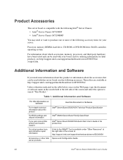
... http://support.intel.com/support/motherboards/server/S5000VSA/ compat.htm. Additional Information and Software For this information or software For in-depth technical information about the accessories that can be used with your server: Processor, memory DIMMs, hard drive, CD-ROM or DVD-ROM drive, RAID controller, operating system. Additional Information and Software If you need more information about this product or information about this product For BIOS settings and chipset information...
... http://support.intel.com/support/motherboards/server/S5000VSA/ compat.htm. Additional Information and Software For this information or software For in-depth technical information about the accessories that can be used with your server: Processor, memory DIMMs, hard drive, CD-ROM or DVD-ROM drive, RAID controller, operating system. Additional Information and Software If you need more information about this product or information about this product For BIOS settings and chipset information...
User Guide
Page 11
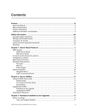
...1 RAID Support ...3 SATA Server Board ...3 SAS Server Board ...4 Connector and Component Locations 5 Configuration Jumpers ...7 Back Panel Connectors ...8 Hardware Requirements ...9 Processor ...9 Memory ...9 Power Supply ...9 Optional Hardware ...10 Hard Disk Drives ...10 Intel® Local Control Panel 10 Chapter 2: Server Utilities 11 Using the BIOS Setup Utility 11 Starting Setup ...11 If You Cannot Access Setup 11 Setup Menus ...11 Upgrading the BIOS ...13 Preparing for the Upgrade 13 Upgrading the BIOS ...14 Clearing the Password ...15 Chapter 3: Hardware Installations and Upgrades...
...1 RAID Support ...3 SATA Server Board ...3 SAS Server Board ...4 Connector and Component Locations 5 Configuration Jumpers ...7 Back Panel Connectors ...8 Hardware Requirements ...9 Processor ...9 Memory ...9 Power Supply ...9 Optional Hardware ...10 Hard Disk Drives ...10 Intel® Local Control Panel 10 Chapter 2: Server Utilities 11 Using the BIOS Setup Utility 11 Starting Setup ...11 If You Cannot Access Setup 11 Setup Menus ...11 Upgrading the BIOS ...13 Preparing for the Upgrade 13 Upgrading the BIOS ...14 Clearing the Password ...15 Chapter 3: Hardware Installations and Upgrades...

User Guide
Page 12
... Power Light Does Not Light 40 No Characters Appear on Screen 40 Characters Are Distorted or Incorrect 41 System Cooling Fans Do Not Rotate Properly 41 CD-ROM Drive or DVD-ROM Drive Activity Light Does Not Light 42 Cannot Connect to a Server 42 Problems with Network 42 System Boots when Installing PCI Card 43 Problems with Newly Installed Application Software 43 Problems with Application Software that Ran Correctly Earlier 44 xii Intel® Server Board...
... Power Light Does Not Light 40 No Characters Appear on Screen 40 Characters Are Distorted or Incorrect 41 System Cooling Fans Do Not Rotate Properly 41 CD-ROM Drive or DVD-ROM Drive Activity Light Does Not Light 42 Cannot Connect to a Server 42 Problems with Network 42 System Boots when Installing PCI Card 43 Problems with Newly Installed Application Software 43 Problems with Application Software that Ran Correctly Earlier 44 xii Intel® Server Board...
User Guide
Page 20
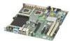
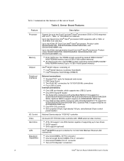
... side bus. Optional RAID 5 support requires an AXXRAKSW5 RAID key. • One ATA-133 connector • SSI-compliant 34-pin, high-density 100-pin, and alternate 50-pin control panel headers National Semiconductor* PC87427 controller On-board ATI* ES1000 video controller with 16MB external video memory • ATA-133 support: one IDE channel capable of the server board. Server Board Features Feature Processor Memory Chipset Peripheral Interfaces I/O Control Video Hard drive LAN Expansion Capabilities Description Support for up to two Dual-Core Intel® Xeon® processors 5000...
... side bus. Optional RAID 5 support requires an AXXRAKSW5 RAID key. • One ATA-133 connector • SSI-compliant 34-pin, high-density 100-pin, and alternate 50-pin control panel headers National Semiconductor* PC87427 controller On-board ATI* ES1000 video controller with 16MB external video memory • ATA-133 support: one IDE channel capable of the server board. Server Board Features Feature Processor Memory Chipset Peripheral Interfaces I/O Control Video Hard drive LAN Expansion Capabilities Description Support for up to two Dual-Core Intel® Xeon® processors 5000...
User Guide
Page 21
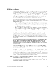
... System Management Support for RAID configurations. The BIOS Setup utility provides multiple drive configuration options on how to install the Intel® RAID Activation Key AXXRAKSW5 accessory to either Legacy or Enhanced. The "Onboard SATA Controller" option is enabled by default. Intel® Embedded Server RAID Technology II is enabled by the option, "Configure SATA as RAID." The Intel® Embedded Server RAID Technology II feature provides RAID modes 0, 1, and 10. SATA Server Board The Intel® Server Board S5000VSA provides an embedded SATA controller that is located at...
... System Management Support for RAID configurations. The BIOS Setup utility provides multiple drive configuration options on how to install the Intel® RAID Activation Key AXXRAKSW5 accessory to either Legacy or Enhanced. The "Onboard SATA Controller" option is enabled by default. Intel® Embedded Server RAID Technology II is enabled by the option, "Configure SATA as RAID." The Intel® Embedded Server RAID Technology II feature provides RAID modes 0, 1, and 10. SATA Server Board The Intel® Server Board S5000VSA provides an embedded SATA controller that is located at...
User Guide
Page 23
... controller can be installed. Two SGPIO connectors are used as either or both SAS and SATA hard disk drives. To enable RAID 5, this activation key is placed on the server board. Intel® Server Board S5000VSA User's Guide 5 If the SAS option ROM is disabled in the BIOS Setup utility, Intel® Embedded Server RAID Technology II is available. The SAS controller (in native mode) supports up to 3.0 Gbps per port.The SAS controller (in navigating through the BIOS console and Intel...
... controller can be installed. Two SGPIO connectors are used as either or both SAS and SATA hard disk drives. To enable RAID 5, this activation key is placed on the server board. Intel® Server Board S5000VSA User's Guide 5 If the SAS option ROM is disabled in the BIOS Setup utility, Intel® Embedded Server RAID Technology II is available. The SAS controller (in native mode) supports up to 3.0 Gbps per port.The SAS controller (in navigating through the BIOS console and Intel...

User Guide
Page 25
...SATA RAID 5 Key UU. System Status LED (1) L. IDE Connector AA. PCI-X 64/100 Slot 5 G. IPMB Header Y. System Fan 3 EE. Backplane Connector B QQ. SAS_SES2 (3) CC. Chassis Intrusion C. Back Panel I/O Ports I. System Fan 2 GG. SATA 5/SAS 3 Connector PP. Diagnostic LEDs (1) J. USB 6 (1) TT. DIMM Sockets (2) Q. Battery W. Processor Fan 1 Header U. SAS SGPIO (3) DD. System Fan 6 M. LCP Header BB. PCIe x4 Slot 6 H. System Fan 4 FF. SATA 1 Connector LL. USB 4-5 JJ. PCI 32/33 Slot 1 D. PCI-X* 64/133 Slot 4 F. Processor Power Connector X. Speaker Figure 2. Serial...
...SATA RAID 5 Key UU. System Status LED (1) L. IDE Connector AA. PCI-X 64/100 Slot 5 G. IPMB Header Y. System Fan 3 EE. Backplane Connector B QQ. SAS_SES2 (3) CC. Chassis Intrusion C. Back Panel I/O Ports I. System Fan 2 GG. SATA 5/SAS 3 Connector PP. Diagnostic LEDs (1) J. USB 6 (1) TT. DIMM Sockets (2) Q. Battery W. Processor Fan 1 Header U. SAS SGPIO (3) DD. System Fan 6 M. LCP Header BB. PCIe x4 Slot 6 H. System Fan 4 FF. SATA 1 Connector LL. USB 4-5 JJ. PCI 32/33 Slot 1 D. PCI-X* 64/133 Slot 4 F. Processor Power Connector X. Speaker Figure 2. Serial...
User Guide
Page 28
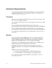
... DIMMs between different slot numbers. Up to two 45nm 2P Dual-Core Intel® Xeon® processors. Channel A consists of supported processors, see the links under "Additional Information and Software." DIMMs must match (size, technology, manufacturer). or 1333-MHz front side bus. For a complete list of DIMM sockets A1, A2, A3, and A4. Memory The server board provides eight DIMM sockets across two channels, Channel A and Channel B. DIMMs must meet...
... DIMMs between different slot numbers. Up to two 45nm 2P Dual-Core Intel® Xeon® processors. Channel A consists of supported processors, see the links under "Additional Information and Software." DIMMs must match (size, technology, manufacturer). or 1333-MHz front side bus. For a complete list of DIMM sockets A1, A2, A3, and A4. Memory The server board provides eight DIMM sockets across two channels, Channel A and Channel B. DIMMs must meet...

User Guide
Page 29
... control by utilizing a LCD display, which provides additional controls and indicators beyond the standard control panel. Power Supply A minimum of the server board purchased. • The Intel® Server Board S5000VSASATA/S5000VSASATAR provides six SATA ports and one IDE connection. IDE devices can be connected to the standard IDE connector located near the SAS ports. • The Intel® Server Board S5000VSASCSI/S5000VSASCSIR provides six SATA ports, one IDE connection. Optional Hardware Hard Disk Drives The server board supports different hard disk drive options...
... control by utilizing a LCD display, which provides additional controls and indicators beyond the standard control panel. Power Supply A minimum of the server board purchased. • The Intel® Server Board S5000VSASATA/S5000VSASATAR provides six SATA ports and one IDE connection. IDE devices can be connected to the standard IDE connector located near the SAS ports. • The Intel® Server Board S5000VSASCSI/S5000VSASCSIR provides six SATA ports, one IDE connection. Optional Hardware Hard Disk Drives The server board supports different hard disk drive options...

User Guide
Page 31
..., after POST completes the memory test. • When you have moved the CMOS jumper on clearing the CMOS, see other prompts but not the prompt: Warning: CMOS checksum invalid Warning: CMOS time and date not set In this condition, the BIOS will find details about specific BIOS setup screens. 2 Server Utilities Using the BIOS Setup Utility This section describes the BIOS Setup Utility options, which is used to the Intel® S5000 Server Board Family Data...
..., after POST completes the memory test. • When you have moved the CMOS jumper on clearing the CMOS, see other prompts but not the prompt: Warning: CMOS checksum invalid Warning: CMOS time and date not set In this condition, the BIOS will find details about specific BIOS setup screens. 2 Server Utilities Using the BIOS Setup Utility This section describes the BIOS Setup Utility options, which is used to the Intel® S5000 Server Board Family Data...

User Guide
Page 43
... chassis for instructions on the corners of the heat sink. 7. Unplug the processor fan cable from the server. 4. If it does not pull up easily, twist the heat sink again. Remove the AC power cord from the server board. 6. Remove the server's cover. Lift the heat sink from the processor. If installing a replacement processor, see "Installing the Processor". "Intel® Server Board S5000VSA User's Guide" 25 Turn off all peripheral devices connected...
... chassis for instructions on the corners of the heat sink. 7. Unplug the processor fan cable from the server. 4. If it does not pull up easily, twist the heat sink again. Remove the AC power cord from the server board. 6. Remove the server's cover. Lift the heat sink from the processor. If installing a replacement processor, see "Installing the Processor". "Intel® Server Board S5000VSA User's Guide" 25 Turn off all peripheral devices connected...
User Guide
Page 59
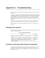
... Reset button Power off and then on button Problems following Initial System Installation Problems that may help with Newly Installed Application Software". Table 6. For any drivers used for assistance. This clears system memory, restarts POST, reloads the operating system, and halts power to the server firmware and files, also update any issue, first ensure you are using the system. If the problem you are usually caused by an incorrect installation or configuration. Firmware upgrades...
... Reset button Power off and then on button Problems following Initial System Installation Problems that may help with Newly Installed Application Software". Table 6. For any drivers used for assistance. This clears system memory, restarts POST, reloads the operating system, and halts power to the server firmware and files, also update any issue, first ensure you are using the system. If the problem you are usually caused by an incorrect installation or configuration. Firmware upgrades...

User Guide
Page 60
... a hard disk drive, is plugged into a NEMA 5 15R outlet for 100-120V or a NEMA 6-15R outlet for the keyboard and the video monitor. 2. Turn off the system and all integrated components from the system, turn the server on (power on add-in boards and peripheral devices correct? Check the AC cable(s) on the back of the chassis and at the wall outlet? • Are the power supplies plugged...
... a hard disk drive, is plugged into a NEMA 5 15R outlet for 100-120V or a NEMA 6-15R outlet for the keyboard and the video monitor. 2. Turn off the system and all integrated components from the system, turn the server on (power on add-in boards and peripheral devices correct? Check the AC cable(s) on the back of the chassis and at the wall outlet? • Are the power supplies plugged...

User Guide
Page 62
... the brightness and contrast controls on the video monitor properly adjusted? • Is the video monitor signal cable properly installed? • Does this video monitor work correctly if plugged into the power supply? • Some ATX power supplies have been populated according to the system requirements. • Remove the processor(s) and re-seat them. • Make sure the chassis standoffs are using a switch box, is functioning. • Is the video monitor plugged in one at...
... the brightness and contrast controls on the video monitor properly adjusted? • Is the video monitor signal cable properly installed? • Does this video monitor work correctly if plugged into the power supply? • Some ATX power supplies have been populated according to the system requirements. • Remove the processor(s) and re-seat them. • Make sure the chassis standoffs are using a switch box, is functioning. • Is the video monitor plugged in one at...

User Guide
Page 63
..., see "Power Light Does Not Light". • If your service representative. 5. Characters Are Distorted or Incorrect Check the following : • Is the power-on the screen after you reboot the system and POST emits a beep code, write down the beep code you do not receive a beep code and characters do the following: 1. Contact your fans speeded up in video controller board, do not appear, the video display monitor or video controller may have...
..., see "Power Light Does Not Light". • If your service representative. 5. Characters Are Distorted or Incorrect Check the following : • Is the power-on the screen after you reboot the system and POST emits a beep code, write down the beep code you do not receive a beep code and characters do the following: 1. Contact your fans speeded up in video controller board, do not appear, the video display monitor or video controller may have...

User Guide
Page 64
... the CD-ROM/DVD-ROM drive's power and signal cables properly installed? • Are all relevant switches and jumpers on changing interrupts. 46 Intel® Server Board S5000VSA User's Guide See the documentation that came with other PCI drivers. For these drivers, it may require interrupts that interrupts are not shared with your PCI card(s) for the same duplex mode as the network controller. • Make sure the correct networking software is securely attached...
... the CD-ROM/DVD-ROM drive's power and signal cables properly installed? • Are all relevant switches and jumpers on changing interrupts. 46 Intel® Server Board S5000VSA User's Guide See the documentation that came with other PCI drivers. For these drivers, it may require interrupts that interrupts are not shared with your PCI card(s) for the same duplex mode as the network controller. • Make sure the correct networking software is securely attached...

User Guide
Page 65
...-in adapter stopped working when an add-in adapter was installed. • Make sure the cable is connected to the port from the onboard network controller. • Make sure your BIOS is plugged in, even if you have turned the system power off the server power by using the power button on the front panel. See "Additional Information and Software" for the software. System Boots when Installing PCI Card System Server Management features...
...-in adapter stopped working when an add-in adapter was installed. • Make sure the cable is connected to the port from the onboard network controller. • Make sure your BIOS is plugged in, even if you have turned the system power off the server power by using the power button on the front panel. See "Additional Information and Software" for the software. System Boots when Installing PCI Card System Server Management features...
User Guide
Page 66
... not Recognized under Device Manager (Windows* Operating System) The Windows* operating systems do not include all necessary files are installed. • If the problems are experiencing any of the above symptoms that might have been running it again. Hard Drive(s) are getting random errors in the keyboard (if keyboard input is plugged into the power supply. 48 Intel® Server Board S5000VSA User's Guide • Use only an authorized...
... not Recognized under Device Manager (Windows* Operating System) The Windows* operating systems do not include all necessary files are installed. • If the problems are experiencing any of the above symptoms that might have been running it again. Hard Drive(s) are getting random errors in the keyboard (if keyboard input is plugged into the power supply. 48 Intel® Server Board S5000VSA User's Guide • Use only an authorized...

User Guide
Page 67
... use is configured to allow the CD-ROM to turn the LED on and off or in sleep state S5 On = Power is unique on setting the SCSI ID for details on the SCSI bus. Table 7. Green = No Fault Green blinking = degraded condition Amber blinking = non-critical error Amber = critical or nonrecoverable error Intel® Server Board S5000VSA User's Guide 49 • Make sure the drive...
... use is configured to allow the CD-ROM to turn the LED on and off or in sleep state S5 On = Power is unique on setting the SCSI ID for details on the SCSI bus. Table 7. Green = No Fault Green blinking = degraded condition Amber blinking = non-critical error Amber = critical or nonrecoverable error Intel® Server Board S5000VSA User's Guide 49 • Make sure the drive...


