Product Specification
Page 16
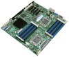
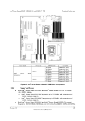
... processor socket) ƒ Channels A, B, C, D, E, and F • Support for 800/1066/1333 MT/s ECC Registered DDR3 Memory (RDIMM), ECC Unbuffered DDR3 memory ((UDIMM) • No support for mixing of RDIMMs and UDIMMs • Intel® Server Board S5520HC/S5520HCT: ƒ...One DIMM slot on Channels D, E, and F • Intel® Server Board S5520HC/S5520HCT: ƒ Intel® 5520 Chipset ƒ Intel® 82801JIR I/O Controller Hub (ICH10R) • Intel® Server Board S5500HCV: ƒ Intel® 5500 Chipset ƒ Intel® 82801JIR I/O Controller Hub (ICH10R) Support for •...
... processor socket) ƒ Channels A, B, C, D, E, and F • Support for 800/1066/1333 MT/s ECC Registered DDR3 Memory (RDIMM), ECC Unbuffered DDR3 memory ((UDIMM) • No support for mixing of RDIMMs and UDIMMs • Intel® Server Board S5520HC/S5520HCT: ƒ...One DIMM slot on Channels D, E, and F • Intel® Server Board S5520HC/S5520HCT: ƒ Intel® 5520 Chipset ƒ Intel® 82801JIR I/O Controller Hub (ICH10R) • Intel® Server Board S5500HCV: ƒ Intel® 5500 Chipset ƒ Intel® 82801JIR I/O Controller Hub (ICH10R) Support for •...

Product Specification
Page 21
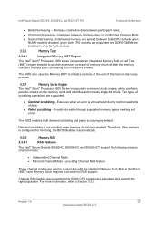
...Intel® Server Boards S5520HC, S5500HCV, and S5520HCT TPS Overview Callout I J K L M N O P Description Mechanically) S5500HCV: Slot 6, PCI Express* Gen2 x4 (x16 Mechanically) Battery Back Panel I/O Ports Diagnostic and Identify LED's System Fan 5 Header (4-pin) Power Connector for Processor 1 and Memory attached to Processor 1 Processor 1 Fan Header (4-pin) DIMM Sockets... 2 and Memory attached to Processor 2 Q Auxiliary Power Signal Connector R Processor 2 Fan Header (4-pin) S DIMM Sockets of Memory Channel D, E, and F T SAS Module Slot U System Fan 3 Header (6-pin) V System Fan ...
...Intel® Server Boards S5520HC, S5500HCV, and S5520HCT TPS Overview Callout I J K L M N O P Description Mechanically) S5500HCV: Slot 6, PCI Express* Gen2 x4 (x16 Mechanically) Battery Back Panel I/O Ports Diagnostic and Identify LED's System Fan 5 Header (4-pin) Power Connector for Processor 1 and Memory attached to Processor 1 Processor 1 Fan Header (4-pin) DIMM Sockets... 2 and Memory attached to Processor 2 Q Auxiliary Power Signal Connector R Processor 2 Fan Header (4-pin) S DIMM Sockets of Memory Channel D, E, and F T SAS Module Slot U System Fan 3 Header (6-pin) V System Fan ...

Product Specification
Page 31
... S5520HC, S5500HCV, and S5520HCT TPS Functional Architecture 3. Intel® 5520 I/O Hub or 5500 I/O Hub, which provides a connection point between various I /O subsystem This chapter provides a high-level description of the Intel® Server Boards S5520HC, S5500HCV and S5520HCTis based on the Intel® Xeon® Processor 5500 Series in an FC-LGA 1366 Socket B package with...
... S5520HC, S5500HCV, and S5520HCT TPS Functional Architecture 3. Intel® 5520 I/O Hub or 5500 I/O Hub, which provides a connection point between various I /O subsystem This chapter provides a high-level description of the Intel® Server Boards S5520HC, S5500HCV and S5520HCTis based on the Intel® Xeon® Processor 5500 Series in an FC-LGA 1366 Socket B package with...

Product Specification
Page 36
... Support tab, look for "Compatibility" and then "Supported Processor List". 3.2.1 Processor Population Rules You must populate Processor socket 1 (CPU 1) before processor socket 2 (CPU 2). System will not boot until the error is enabled or disabled. z Minor: The message is ...pauses at a blank screen with the error code. Functional Architecture Intel® Server Boards S5520HC, S5500HCV, and S5520HCT TPS 3.2 Processor Support The Intel® Server Boards S5520HC, S5500HCV and S5520HCT support the following table describes mixed processor conditions and recommended actions...
... Support tab, look for "Compatibility" and then "Supported Processor List". 3.2.1 Processor Population Rules You must populate Processor socket 1 (CPU 1) before processor socket 2 (CPU 2). System will not boot until the error is enabled or disabled. z Minor: The message is ...pauses at a blank screen with the error code. Functional Architecture Intel® Server Boards S5520HC, S5500HCV, and S5520HCT TPS 3.2 Processor Support The Intel® Server Boards S5520HC, S5500HCV and S5520HCT support the following table describes mixed processor conditions and recommended actions...
Product Specification
Page 39
...material (TIM). The server boards ship with Unified Retention System (URS) and Unified Backplate Assembly. Intel® Server Boards S5520HC, S5500HCV, and S5520HCT TPS Functional Architecture z Intel® 64 mode when 64-bit extension technology is enabled. 3.2.7 Core Multi-Processing The BIOS ... server boards comply with Unified Backplate Assembly at each processor socket. The URS retention transfers load to minimize cache misses when a demand read is removable, allowing for the stacking order of non-Intel® heatsink retention solutions. The Unified Backplate Assembly is ...
...material (TIM). The server boards ship with Unified Retention System (URS) and Unified Backplate Assembly. Intel® Server Boards S5520HC, S5500HCV, and S5520HCT TPS Functional Architecture z Intel® 64 mode when 64-bit extension technology is enabled. 3.2.7 Core Multi-Processing The BIOS ... server boards comply with Unified Backplate Assembly at each processor socket. The URS retention transfers load to minimize cache misses when a demand read is removable, allowing for the stacking order of non-Intel® heatsink retention solutions. The Unified Backplate Assembly is ...
Product Specification
Page 41
... and groups DIMMs on the board provide information about which channel/CPU Socket they belong to processor sockets. z DIMMs are organized into autonomous memory. 3.3.1 Memory Subsystem Nomenclature The nomenclature for DIMM sockets implemented in the Intel® Server Boards S5520HC, S5500HCV and S5520HCT is represented in twoprocessor configuration. DIMM_D1 is the first slot on CPU...
... and groups DIMMs on the board provide information about which channel/CPU Socket they belong to processor sockets. z DIMMs are organized into autonomous memory. 3.3.1 Memory Subsystem Nomenclature The nomenclature for DIMM sockets implemented in the Intel® Server Boards S5520HC, S5500HCV and S5520HCT is represented in twoprocessor configuration. DIMM_D1 is the first slot on CPU...
Product Specification
Page 43
...; Server Board S5500HCV supports up to 9 DIMMs with a maximum of 144GB memory capacity. Revision 1.8 29 Intel order number E39529-013 Intel® Server Boards S5520HC, S5500HCV, and S5520HCT TPS Functional Architecture Server Board CPU Socket Intel® Server S5500HCV CPU 1 Board CPU 2 DIMM Identifier A1 (Blue) A2 (Black) B1 (Blue) B2 (Black) C1 (Blue) C2...
...; Server Board S5500HCV supports up to 9 DIMMs with a maximum of 144GB memory capacity. Revision 1.8 29 Intel order number E39529-013 Intel® Server Boards S5520HC, S5500HCV, and S5520HCT TPS Functional Architecture Server Board CPU Socket Intel® Server S5500HCV CPU 1 Board CPU 2 DIMM Identifier A1 (Blue) A2 (Black) B1 (Blue) B2 (Black) C1 (Blue) C2...
Product Specification
Page 47
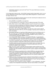
...; Server Boards S5520HC, S5500HCV and S5520HCT support the following memory channel modes: • Independent Channel Mode • Mirrored Channel Mode - Two types of scrubbing operations are populated and support the right population. The BIOS enables both sockets. 3.3.6 Memory Test 3.3.6.1 Integrated Memory BIST Engine The Intel® Xeon® Processor 5500 series incorporate an...
...; Server Boards S5520HC, S5500HCV and S5520HCT support the following memory channel modes: • Independent Channel Mode • Mirrored Channel Mode - Two types of scrubbing operations are populated and support the right population. The BIOS enables both sockets. 3.3.6 Memory Test 3.3.6.1 Integrated Memory BIST Engine The Intel® Xeon® Processor 5500 series incorporate an...
Product Specification
Page 49
... two modes are associated with remote memory in slot A1. 7. If both CPU sockets, then Mirrored Channel Mode can use the Independent Channel mode to obtain the best performance from the system: 1. Intel® Server Boards S5520HC, S5500HCV, and S5520HCT TPS Functional Architecture • Optimization techniques used by the BIOS. 8. The following general...
... two modes are associated with remote memory in slot A1. 7. If both CPU sockets, then Mirrored Channel Mode can use the Independent Channel mode to obtain the best performance from the system: 1. Intel® Server Boards S5520HC, S5500HCV, and S5520HCT TPS Functional Architecture • Optimization techniques used by the BIOS. 8. The following general...
Product Specification
Page 50
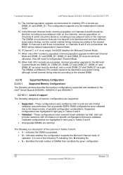
...DIMM_B1 must DIMM_D1 and DIMM_E1 as a pair must be identical, including across adjacent slots on the Intel® Server Boards S5520HC, S5500HCV and S5520HCT. 3.3.10.1.1 Levels of support The following categories of DIMMs that were validated. These configurations have ...enabling CPU 2 socket are DIMM_A1, DIMM_B1, DIMM_D1 and DIMM_E1. These configurations were verified by Intel. Indicates the DIMM is not empty, the BIOS disables the Mirrored Channel Mode. 17. N indicating No. ƒ N - Functional Architecture Intel® Server Boards S5520HC, S5500HCV, and S5520HCT TPS 14....
...DIMM_B1 must DIMM_D1 and DIMM_E1 as a pair must be identical, including across adjacent slots on the Intel® Server Boards S5520HC, S5500HCV and S5520HCT. 3.3.10.1.1 Levels of support The following categories of DIMMs that were validated. These configurations have ...enabling CPU 2 socket are DIMM_A1, DIMM_B1, DIMM_D1 and DIMM_E1. These configurations were verified by Intel. Indicates the DIMM is not empty, the BIOS disables the Mirrored Channel Mode. 17. N indicating No. ƒ N - Functional Architecture Intel® Server Boards S5520HC, S5500HCV, and S5520HCT TPS 14....
Product Specification
Page 51
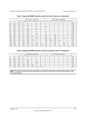
... X N 5 3 X X X N 6 3 X X X N 7 3 X X X N 8 4 X X X X N 9 4 X X X X Y 10 6 X X X X X X Y 11 6 X X X X X X N 12 7 X X X X X X X N 13 8 X X X X X X X X Y 14 8 X X X X X X X X N 15 9 X X X X X X X X X N 16 12 X X X X X X X X X X X X N Table 6. Intel® Server Boards S5520HC, S5500HCV, and S5520HCT TPS Functional Architecture Table 5. Supported DIMM Population under the Single Processor Configuration # N CPU1 Socket = Populated CPU2 Socket = Empty A1 A2 B1 B2 C1 C2 D1 D2 E1 E2 F1 F2...
... X N 5 3 X X X N 6 3 X X X N 7 3 X X X N 8 4 X X X X N 9 4 X X X X Y 10 6 X X X X X X Y 11 6 X X X X X X N 12 7 X X X X X X X N 13 8 X X X X X X X X Y 14 8 X X X X X X X X N 15 9 X X X X X X X X X N 16 12 X X X X X X X X X X X X N Table 6. Intel® Server Boards S5520HC, S5500HCV, and S5520HCT TPS Functional Architecture Table 5. Supported DIMM Population under the Single Processor Configuration # N CPU1 Socket = Populated CPU2 Socket = Empty A1 A2 B1 B2 C1 C2 D1 D2 E1 E2 F1 F2...
Product Specification
Page 93
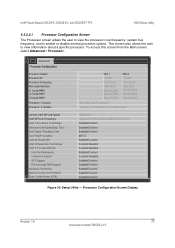
... to enable or disable several processor options. Processor Configuration Screen Display Revision 1.8 79 Intel order number E39529-013 Intel® Server Boards S5520HC, S5500HCV, and S5520HCT TPS BIOS Setup Utility 5.3.2.2.1 Processor Configuration Screen The Processor screen allows the user to... Processor Socket Processor ID Processor Frequency Microcode Revision L1 Cache RAM L2 Cache RAM L3 Cache RAM Processor 1 Version Processor 2 Version Current Intel® QPI Link Speed Intel® QPI Link Frequency Intel® Turbo Boost Technology Enhanced Intel SpeedStep® Tech Intel®...
... to enable or disable several processor options. Processor Configuration Screen Display Revision 1.8 79 Intel order number E39529-013 Intel® Server Boards S5520HC, S5500HCV, and S5520HCT TPS BIOS Setup Utility 5.3.2.2.1 Processor Configuration Screen The Processor screen allows the user to... Processor Socket Processor ID Processor Frequency Microcode Revision L1 Cache RAM L2 Cache RAM L3 Cache RAM Processor 1 Version Processor 2 Version Current Intel® QPI Link Speed Intel® QPI Link Frequency Intel® Turbo Boost Technology Enhanced Intel SpeedStep® Tech Intel®...
Product Specification
Page 97
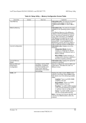
...: System memory is enabled. - Installed: There is running at. Comments Information only. Select to a different screen. Each DIMM socket field reflects one of all DDR3 DIMMs that failed Memory BIST during memory discovery phase in this slot was disabled by the BIOS ...is configured for maximum reliability in this slot. - Displays the state of memory mirroring. Information only. Intel® Server Boards S5520HC, S5500HCV, and S5520HCT TPS BIOS Setup Utility Setup Item Total Memory Effective Memory Current Configuration Current Memory Speed Memory RAS and ...
...: System memory is enabled. - Installed: There is running at. Comments Information only. Select to a different screen. Each DIMM socket field reflects one of all DDR3 DIMMs that failed Memory BIST during memory discovery phase in this slot was disabled by the BIOS ...is configured for maximum reliability in this slot. - Displays the state of memory mirroring. Information only. Intel® Server Boards S5520HC, S5500HCV, and S5520HCT TPS BIOS Setup Utility Setup Item Total Memory Effective Memory Current Configuration Current Memory Speed Memory RAS and ...
Product Specification
Page 122
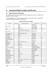
... board and the corresponding preference designators printed on the server boards. Table 46. Connector/Header Locations and Pin-outs Intel® Server Boards S5520HC, S5500HCV, and S5520HCT TPS 6. Connector/Header Locations and Pin-outs 6.1 Board Connector Information The following table lists all connectors, headers,..., J1E3, J1F1, J1F4 J1F5, J1G3 J1G2 J1G6 Connector Type Main power CPU 1 power CPU 2 Power P/S aux/IPMB CPU sockets DIMM sockets Card edge Card edge Card edge Mezzanine Mezzanine Key holder Header Header Header Battery holder External LAN built-in magnetic and dual USB ...
... board and the corresponding preference designators printed on the server boards. Table 46. Connector/Header Locations and Pin-outs Intel® Server Boards S5520HC, S5500HCV, and S5520HCT TPS 6. Connector/Header Locations and Pin-outs 6.1 Board Connector Information The following table lists all connectors, headers,..., J1E3, J1F1, J1F4 J1F5, J1G3 J1G2 J1G6 Connector Type Main power CPU 1 power CPU 2 Power P/S aux/IPMB CPU sockets DIMM sockets Card edge Card edge Card edge Mezzanine Mezzanine Key holder Header Header Header Battery holder External LAN built-in magnetic and dual USB ...
Product Specification
Page 140
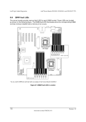
These LEDs are empty in the following figure. DIMM Fault LED's Location 126 Revision 1.8 Intel order number E39529-013 The DIMM fault LED illuminates when the corresponding DIMM slot has memory installed and a memory error occurs. * D2, E2, and F2 DIMM slot and Fault LED's are located as shown in Intel® Server Board S5500HCV Figure 57. Intel® Light Guided Diagnostics Intel® Server Boards S5520HC, S5500HCV, and S5520HCT TPS 8.4 DIMM Fault LEDs The server boards provide memory fault LED for each DIMM socket.
These LEDs are empty in the following figure. DIMM Fault LED's Location 126 Revision 1.8 Intel order number E39529-013 The DIMM fault LED illuminates when the corresponding DIMM slot has memory installed and a memory error occurs. * D2, E2, and F2 DIMM slot and Fault LED's are located as shown in Intel® Server Board S5500HCV Figure 57. Intel® Light Guided Diagnostics Intel® Server Boards S5520HC, S5500HCV, and S5520HCT TPS 8.4 DIMM Fault LEDs The server boards provide memory fault LED for each DIMM socket.
Product Specification
Page 159
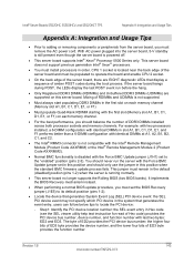
... jumper must remain in order. This server board does not support previous generation Intel® Xeon® processors. • You must be populated to the "enabled" position (pins 2-3). CPU 1 socket is not supported. • Must always start populating DDR3 DIMMs in this position...server board no longer supports the Rolling BIOS (two BIOS banks). If the server board hangs during the boot process. Intel® Server Boards S5520HC, S5500HCV, and S5520HCT TPS Appendix A: Integration and Usage Tips Appendix A: Integration and Usage Tips • Prior to its default position (pins ...
... jumper must remain in order. This server board does not support previous generation Intel® Xeon® processors. • You must be populated to the "enabled" position (pins 2-3). CPU 1 socket is not supported. • Must always start populating DDR3 DIMMs in this position...server board no longer supports the Rolling BIOS (two BIOS banks). If the server board hangs during the boot process. Intel® Server Boards S5520HC, S5500HCV, and S5520HCT TPS Appendix A: Integration and Usage Tips Appendix A: Integration and Usage Tips • Prior to its default position (pins ...
Product Specification
Page 183
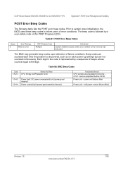
... CPU2. soft power control failure offset. Prior to system video initialization, the BIOS uses these beep codes to the memory was detected. Intel® Server Boards S5520HC, S5500HCV and S5520HCT TPS Appendix F: POST Error Messages and Handling POST Error Beep Codes The following table lists the POST error beep codes. Associated Sensors...
... CPU2. soft power control failure offset. Prior to system video initialization, the BIOS uses these beep codes to the memory was detected. Intel® Server Boards S5520HC, S5500HCV and S5520HCT TPS Appendix F: POST Error Messages and Handling POST Error Beep Codes The following table lists the POST error beep codes. Associated Sensors...

