Service Guide
Page 5
... installing or replacing components such as the memory, processor, front panel board, and battery, among other components you will also find BIOS error messages and POST code messages. Information about the specific BIOS settings and screens is written for system technicians responsible for troubleshooting, upgrading, and repairing this Manual Thank you identify components and their locations. In this manual, refer to identify the source of the Intel® Workstation Board S5520SC. Chapter 2 provides instructions on using the Intel...
... installing or replacing components such as the memory, processor, front panel board, and battery, among other components you will also find BIOS error messages and POST code messages. Information about the specific BIOS settings and screens is written for system technicians responsible for troubleshooting, upgrading, and repairing this Manual Thank you identify components and their locations. In this manual, refer to identify the source of the Intel® Workstation Board S5520SC. Chapter 2 provides instructions on using the Intel...
Service Guide
Page 6
... with this product Use this Document or Software Intel® Workstation Board S5520SC Technical Product Specification. These files are available at : http://support.intel.com/support/motherboards/server/S5520SC/ See the section on the web page titled, "Installation and Use" or using the Server Configurator Tool described next. Preface „ Memory DIMMs „ Hard drive „ USB floppy drive „ CD-ROM or DVD-ROM drive „ RAID controller „ Operating system For information about which accessories, memory, processors, and third...
... with this product Use this Document or Software Intel® Workstation Board S5520SC Technical Product Specification. These files are available at : http://support.intel.com/support/motherboards/server/S5520SC/ See the section on the web page titled, "Installation and Use" or using the Server Configurator Tool described next. Preface „ Memory DIMMs „ Hard drive „ USB floppy drive „ CD-ROM or DVD-ROM drive „ RAID controller „ Operating system For information about which accessories, memory, processors, and third...
Service Guide
Page 8
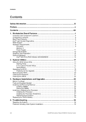
... Upgrades 23 Before You Begin...23 Tools and Supplies Needed 23 Installing and Removing Memory 23 Installing DIMMs ...23 Removing DIMMs ...24 Installing or Replacing the Processor 24 Installing the Processor 25 Installing the Processor Heatsink(s 27 Replacing the Processor 29 Replacing the CMOS Battery 30 4. Workstation Board Features 1 Connector and Component Locations 4 Configuration Jumpers...5 Back Panel Features ...6 Intel® Light-Guided Diagnostics 7 RAID Support ...8 Hardware Requirements ...9 Processor ...9 Memory 9 Power Supply ...11 Storage Mode Matrix ...12 Graphics...
... Upgrades 23 Before You Begin...23 Tools and Supplies Needed 23 Installing and Removing Memory 23 Installing DIMMs ...23 Removing DIMMs ...24 Installing or Replacing the Processor 24 Installing the Processor 25 Installing the Processor Heatsink(s 27 Replacing the Processor 29 Replacing the CMOS Battery 30 4. Workstation Board Features 1 Connector and Component Locations 4 Configuration Jumpers...5 Back Panel Features ...6 Intel® Light-Guided Diagnostics 7 RAID Support ...8 Hardware Requirements ...9 Processor ...9 Memory 9 Power Supply ...11 Storage Mode Matrix ...12 Graphics...

Service Guide
Page 9
... 35 CD-ROM Drive or DVD-ROM Drive Activity Light Does Not Light 36 Cannot Connect to a Server 36 Problems with Network 36 System Boots when Installing PCI Card 37 Problems with Newly Installed Application Software 37 Problems with Application Software that Ran Correctly Earlier 37 Devices are not Recognized under Device Manager (Microsoft Windows* Operating System) ...38 Hard Drive(s) are not Recognized 38 Bootable CD-ROM/DVD-ROM Disk Is Not Detected 38 LED Information ...39 BIOS POST Beep Codes 39 Appendix...
... 35 CD-ROM Drive or DVD-ROM Drive Activity Light Does Not Light 36 Cannot Connect to a Server 36 Problems with Network 36 System Boots when Installing PCI Card 37 Problems with Newly Installed Application Software 37 Problems with Application Software that Ran Correctly Earlier 37 Devices are not Recognized under Device Manager (Microsoft Windows* Operating System) ...38 Hard Drive(s) are not Recognized 38 Bootable CD-ROM/DVD-ROM Disk Is Not Detected 38 LED Information ...39 BIOS POST Beep Codes 39 Appendix...
Service Guide
Page 10
... Table 1. Storage Mode Matrix ...12 Table 5. Keyboard Commands ...18 Table 7. POST Error Beep Codes 32 Table 9. Configuration Jumper Location 5 Figure 4. Removing the Processor Socket Protective Cover 26 Figure 15. Workstation Board Features 1 Table 2. Password Clear Jumper 21 Figure 10. BMC POST Error Beep Codes 39 Table 11. Product Certification Markings 41 x Intel® Workstation Board S5520SC Service Guide Intel® Workstation Board S5520SC Connector and Component Locations 4 Figure 3. Intel® SAS Entry RAID Module 15 Figure 8. Installing Memory ...23...
... Table 1. Storage Mode Matrix ...12 Table 5. Keyboard Commands ...18 Table 7. POST Error Beep Codes 32 Table 9. Configuration Jumper Location 5 Figure 4. Removing the Processor Socket Protective Cover 26 Figure 15. Workstation Board Features 1 Table 2. Password Clear Jumper 21 Figure 10. BMC POST Error Beep Codes 39 Table 11. Product Certification Markings 41 x Intel® Workstation Board S5520SC Service Guide Intel® Workstation Board S5520SC Connector and Component Locations 4 Figure 3. Intel® SAS Entry RAID Module 15 Figure 8. Installing Memory ...23...
Service Guide
Page 11
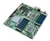
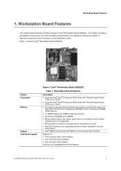
...; Mixing memory type, size, speed, and/or rank on this platform has not been validated and is not supported ƒ Mixing memory vendors is not supported on the workstation board. Feature Processors Memory Chipset Cooling fan support Figure 1. Intel® Workstation Board S5520SC Table 1. Intel® Workstation Board S5520SC Service Guide 1 Workstation Board Features 1. This chapter provides a photograph of the product, list of the workstation board features, and diagrams showing the location of important components and connections on this platform by Intel ƒ...
...; Mixing memory type, size, speed, and/or rank on this platform has not been validated and is not supported ƒ Mixing memory vendors is not supported on the workstation board. Feature Processors Memory Chipset Cooling fan support Figure 1. Intel® Workstation Board S5520SC Table 1. Intel® Workstation Board S5520SC Service Guide 1 Workstation Board Features 1. This chapter provides a photograph of the product, list of the workstation board features, and diagrams showing the location of important components and connections on this platform by Intel ƒ...

Service Guide
Page 17
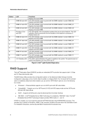
... a fault occurred with the fan installed on the Workstation board System Fan 5 header. Intel® Workstation Board S5520SC Service Guide 7 Intel® Light-Guided Diagnostics Workstation Board Features Callout A. C. LED System Status LED ID LED POST Diagnostics LEDs System fan 5 fault LED Processor 1 fan fault LED DIMM C1 fault LED DIMM C2 fault LED DIMM B1 fault LED Functions The status LED indicates whether a system is grouped with the DIMM installed in socket DIMM_C2. Replace faulty unit. Replace the faulty DIMM. E. H. This LED indicates a fault occurred...
... a fault occurred with the fan installed on the Workstation board System Fan 5 header. Intel® Workstation Board S5520SC Service Guide 7 Intel® Light-Guided Diagnostics Workstation Board Features Callout A. C. LED System Status LED ID LED POST Diagnostics LEDs System fan 5 fault LED Processor 1 fan fault LED DIMM C1 fault LED DIMM C2 fault LED DIMM B1 fault LED Functions The status LED indicates whether a system is grouped with the DIMM installed in socket DIMM_C2. Replace faulty unit. Replace the faulty DIMM. E. H. This LED indicates a fault occurred...
Service Guide
Page 18
...of the workstation board. The BIOS Setup Utility provides drive configuration options on for processor 2. Supports up to four SATA ports [0/1/2/3] with IDE Legacy mode and two SATA ports [4/5] with the DIMM installed in socket DIMM_E1. L. O. If RAID 5 is enabled by "SW RAID" mode. K. Replace the faulty DIMM. Replace the faulty DIMM. This LED indicates a fault occurred with IDE Native Mode. „ "AHCI" - This LED indicates a fault occurred with the activation key. 8 Intel® Workstation Board S5520SC Service Guide Replace the faulty DIMM. M. Replace the...
...of the workstation board. The BIOS Setup Utility provides drive configuration options on for processor 2. Supports up to four SATA ports [0/1/2/3] with IDE Legacy mode and two SATA ports [4/5] with the DIMM installed in socket DIMM_E1. L. O. If RAID 5 is enabled by "SW RAID" mode. K. Replace the faulty DIMM. Replace the faulty DIMM. This LED indicates a fault occurred with IDE Native Mode. „ "AHCI" - This LED indicates a fault occurred with the activation key. 8 Intel® Workstation Board S5520SC Service Guide Replace the faulty DIMM. M. Replace the...
Service Guide
Page 19
...; Channel F contains DIMM sockets F1 and F2 Intel® Workstation Board S5520SC Service Guide 9 Workstation Board Features When Intel® Embedded Server RAID Technology II is enabled with embedded SATA controller, enclosure management is provided through the SATA_SGPIO connector on the workstation board when a cable is available at : http://www.intel.com/support/motherboards/server/S5520SC/howto.htm For help with Hot-swap Drive Backplanes. For information about configure RAID, see the links under "Additional Information and Software". Processor...
...; Channel F contains DIMM sockets F1 and F2 Intel® Workstation Board S5520SC Service Guide 9 Workstation Board Features When Intel® Embedded Server RAID Technology II is enabled with embedded SATA controller, enclosure management is provided through the SATA_SGPIO connector on the workstation board when a cable is available at : http://www.intel.com/support/motherboards/server/S5520SC/howto.htm For help with Hot-swap Drive Backplanes. For information about configure RAID, see the links under "Additional Information and Software". Processor...

Service Guide
Page 25
... the RAID software user's guide at: http://www.intel.com/support/motherboards/server/S5520SC/howto.htm Intel® Workstation Board S5520SC Service Guide 15 If RAID 5 is present. For information on how to configure RAID. Intel® ESRTII Mode Intel® Embedded Server RAID Technology II (Intel® ESRTII) feature provides RAID modes 0, 1, and 10. Intel® SAS Entry RAID Module SAS RAID Support The BIOS Setup Utility provides drive configuration options on the Intel® SAS Entry RAID Module AXX4SASMOD. When Intel® Embedded Server RAID Technology II is enabled...
... the RAID software user's guide at: http://www.intel.com/support/motherboards/server/S5520SC/howto.htm Intel® Workstation Board S5520SC Service Guide 15 If RAID 5 is present. For information on how to configure RAID. Intel® ESRTII Mode Intel® Embedded Server RAID Technology II (Intel® ESRTII) feature provides RAID modes 0, 1, and 10. Intel® SAS Entry RAID Module SAS RAID Support The BIOS Setup Utility provides drive configuration options on the Intel® SAS Entry RAID Module AXX4SASMOD. When Intel® Embedded Server RAID Technology II is enabled...

Service Guide
Page 26
Hard Disk Drives The Intel® Workstation Board S5520SC supports different hard disk driver options. „ USB or Serial SATA (SATA) Solid State Drives „ Serial SATA (SATA) and Serial Attached SCSI (SAS): - Supports for Pedestal Systems with Hot-swap Drive Backplanes. Keyboard, video, and mouse control (KVM) is to cable out the Intel® Workstation Board S5520SC on your server chassis. For example, you can purchase and install the Intel® RAID Activation Key AXXRAKSW5 to enable Software RAID 5 support on -board video to a managing system. Internal Video Cable ...
Hard Disk Drives The Intel® Workstation Board S5520SC supports different hard disk driver options. „ USB or Serial SATA (SATA) Solid State Drives „ Serial SATA (SATA) and Serial Attached SCSI (SAS): - Supports for Pedestal Systems with Hot-swap Drive Backplanes. Keyboard, video, and mouse control (KVM) is to cable out the Intel® Workstation Board S5520SC on your server chassis. For example, you can purchase and install the Intel® RAID Activation Key AXXRAKSW5 to enable Software RAID 5 support on -board video to a managing system. Internal Video Cable ...
Service Guide
Page 29
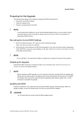
... Key if you want to a file. Obtaining the Upgrade Download the BIOS image file to service. Intel® Workstation Board S5520SC Service Guide 19 Boot the computer and press when you see the following steps explain how to prepare to upgrade the BIOS including how to: ƒ Record the current BIOS settings ƒ Obtain the upgrade utility ƒ Prepare a storage media for the utility / NOTE In the unlikely event a BIOS error occurs during the BIOS update...
... Key if you want to a file. Obtaining the Upgrade Download the BIOS image file to service. Intel® Workstation Board S5520SC Service Guide 19 Boot the computer and press when you see the following steps explain how to prepare to upgrade the BIOS including how to: ƒ Record the current BIOS settings ƒ Obtain the upgrade utility ƒ Prepare a storage media for the utility / NOTE In the unlikely event a BIOS error occurs during the BIOS update...
Service Guide
Page 39
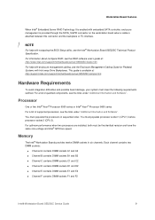
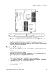
... so could damage the processor. 9. Locating Active Heatsink Cable Connections 8. Turn off the server. 3. Lift the heatsink from the processor - Lift the processor socket lever. 10. See Figure 19 to locate the processor fan headers. 9. Replacing the Processor 1. Do not force the heatsink from the processor. Hardware Installations and Upgrades Callout Processor Heatsink Connector Callout Processor Heatsink Connector A. CPU_2 Figure 19. See the documentation that came with your server chassis for instructions on removing the workstation's cover. 5. Observe the safety...
... so could damage the processor. 9. Locating Active Heatsink Cable Connections 8. Turn off the server. 3. Lift the heatsink from the processor - Lift the processor socket lever. 10. See Figure 19 to locate the processor fan headers. 9. Replacing the Processor 1. Do not force the heatsink from the processor. Hardware Installations and Upgrades Callout Processor Heatsink Connector Callout Processor Heatsink Connector A. CPU_2 Figure 19. See the documentation that came with your server chassis for instructions on removing the workstation's cover. 5. Observe the safety...

Service Guide
Page 40
... of the battery until it loses voltage, and the system settings stored in CMOS RAM in the absence of explosion if battery is incorrectly replaced. Use a finger to weaken, it clears the battery. Reinstall and reconnect any parts you do not bend the lever. 30 Intel® Workstation Board S5520SC Service Guide See the documentation that came with your chassis for instructions on installing the cover. Contact your chassis for example...
... of the battery until it loses voltage, and the system settings stored in CMOS RAM in the absence of explosion if battery is incorrectly replaced. Use a finger to weaken, it clears the battery. Reinstall and reconnect any parts you do not bend the lever. 30 Intel® Workstation Board S5520SC Service Guide See the documentation that came with your chassis for instructions on installing the cover. Contact your chassis for example...

Service Guide
Page 41
... the processor sockets. Remove the new battery from the socket. See the documentation that came with your chassis for instructions on installing the cover. 12. Dispose of the battery socket, towards the rear USB/NIC ports. 10. Replace the chassis cover and reconnect the AC power cord. Run the BIOS Setup utility to restore the configuration settings to observe the correct polarity, insert the battery into the battery socket. Locating and Removing the CMOS Battery 7. Intel® Workstation Board S5520SC Service Guide 31...
... the processor sockets. Remove the new battery from the socket. See the documentation that came with your chassis for instructions on installing the cover. 12. Dispose of the battery socket, towards the rear USB/NIC ports. 10. Replace the chassis cover and reconnect the AC power cord. Run the BIOS Setup utility to restore the configuration settings to observe the correct polarity, insert the battery into the battery socket. Locating and Removing the CMOS Battery 7. Intel® Workstation Board S5520SC Service Guide 31...

Service Guide
Page 42
... sockets on add-in ? Are all jumper and switch settings on the workstation board? 5. If the system has a hard disk drive, is with a specific software application, see "Problems with Newly Installed Application Software". For a link to this : Soft boot reset to all add-in PCI boards fully seated in the proper location and not touching any components, causing a potential short? 6. Are the power supplies plugged in boards and peripheral devices correct? Are all peripherals, clears system memory...
... sockets on add-in ? Are all jumper and switch settings on the workstation board? 5. If the system has a hard disk drive, is with a specific software application, see "Problems with Newly Installed Application Software". For a link to this : Soft boot reset to all add-in PCI boards fully seated in the proper location and not touching any components, causing a potential short? 6. Are the power supplies plugged in boards and peripheral devices correct? Are all peripherals, clears system memory...
Service Guide
Page 43
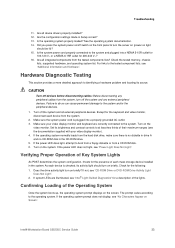
... "Intel® Light-Guided Diagnostics" for the keyboard and video monitor, disconnect each device from the tested components lists? Set its brightness and contrast controls to at least two thirds of the lights. Check for 200-240 V∼? 16. Intel® Workstation Board S5520SC Service Guide 33 Troubleshooting 11. Are all integrated components from the system. 2. Make sure the system power cord is checked, its source. Turn on the screen. See...
... "Intel® Light-Guided Diagnostics" for the keyboard and video monitor, disconnect each device from the tested components lists? Set its brightness and contrast controls to at least two thirds of the lights. Check for 200-240 V∼? 16. Intel® Workstation Board S5520SC Service Guide 33 Troubleshooting 11. Are all integrated components from the system. 2. Make sure the system power cord is checked, its source. Turn on the screen. See...

Service Guide
Page 44
... use a switch box, is it by turning the "Num Lock" function on the screen appear distorted or incorrect. ƒ System cooling fans do not rotate. ƒ CD-ROM or DVD-ROM drive activity light does not light. ƒ There are problems with the system requirements. 8. If so, the power LED might be defective or the cable from the front panel to the correct system? 34 Intel® Workstation Board S5520SC Service Guide Remove...
... use a switch box, is it by turning the "Num Lock" function on the screen appear distorted or incorrect. ƒ System cooling fans do not rotate. ƒ CD-ROM or DVD-ROM drive activity light does not light. ƒ There are problems with the system requirements. 8. If so, the power LED might be defective or the cable from the front panel to the correct system? 34 Intel® Workstation Board S5520SC Service Guide Remove...

Service Guide
Page 47
.... System Boots when Installing PCI Card System Server Management features require full-time "standby" power. This means some parts of the system. „ Unplug the AC power cord(s) from a diskette, CD-ROM, or DVD-ROM, try a different slot if necessary. „ The network driver files may be corrupt or deleted. See the software documentation. 3. Unauthorized copies often do not work. 4. Check the following: 1. If the problems persist...
.... System Boots when Installing PCI Card System Server Management features require full-time "standby" power. This means some parts of the system. „ Unplug the AC power cord(s) from a diskette, CD-ROM, or DVD-ROM, try a different slot if necessary. „ The network driver files may be corrupt or deleted. See the software documentation. 3. Unauthorized copies often do not work. 4. Check the following: 1. If the problems persist...

Quick Start Guide
Page 1
... sure that are using a non-Intel server chassis, see the Intel® Workstation Board S5520SC Service Guide, available on each workstation board socket. For a complete list of compatible processors, heat sinks, and memory, see: http://support.intel.com/support/motherboards/server/s5520SC/ CAUTION: In the Intel® Server Chassis SC5600Base In the Intel® Server Chassis SC5650WS Supported Processor Maximum 95 Maximum 130 watt processor watt processor Supported Graphics Card One maximum ONE maximum 300 watt graphics card in 150 watt graphics PCI Express* Slot 6 or TWO...
... sure that are using a non-Intel server chassis, see the Intel® Workstation Board S5520SC Service Guide, available on each workstation board socket. For a complete list of compatible processors, heat sinks, and memory, see: http://support.intel.com/support/motherboards/server/s5520SC/ CAUTION: In the Intel® Server Chassis SC5600Base In the Intel® Server Chassis SC5650WS Supported Processor Maximum 95 Maximum 130 watt processor watt processor Supported Graphics Card One maximum ONE maximum 300 watt graphics card in 150 watt graphics PCI Express* Slot 6 or TWO...


