Service Guide
Page 5
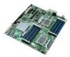
... manual, refer to: http://support.intel.com/support/motherboards/server/S5520SC/ Manual Organization Chapter 1 provides a brief overview of the product, and product diagrams to update the system. In this chapter, you will find a list of the workstation board features, photos of the Intel® Workstation Board S5520SC. In this chapter, you will find BIOS error messages and POST code messages...
... manual, refer to: http://support.intel.com/support/motherboards/server/S5520SC/ Manual Organization Chapter 1 provides a brief overview of the product, and product diagrams to update the system. In this chapter, you will find a list of the workstation board features, photos of the Intel® Workstation Board S5520SC. In this chapter, you will find BIOS error messages and POST code messages...
Service Guide
Page 6
...; Workstation Board S5520SC Quick Start User's Guide in -depth technical information about the accessories that you can be used with your board, and for ordering information for Intel products, see: http://support.intel.com/support/motherboards/server/S5520SC/compat.htm Additional Information and Software If you need more information about this product or information about this product, including BIOS...
...; Workstation Board S5520SC Quick Start User's Guide in -depth technical information about the accessories that you can be used with your board, and for ordering information for Intel products, see: http://support.intel.com/support/motherboards/server/S5520SC/compat.htm Additional Information and Software If you need more information about this product or information about this product, including BIOS...

Service Guide
Page 7
... and Use". Power Budget Analysis Tool. Available at : http://www.intel.com/go/servermanagement Intel® Workstation Board S5520SC Service Guide vii Available at : http://support.intel.com/support/motherboards/server/S5520SC/. To make sure your system falls within the allowed power budget For latest drivers, firmware updates (BIOS, BMC, FRUSDR, and ME), and utilities For software to manage...
... and Use". Power Budget Analysis Tool. Available at : http://www.intel.com/go/servermanagement Intel® Workstation Board S5520SC Service Guide vii Available at : http://support.intel.com/support/motherboards/server/S5520SC/. To make sure your system falls within the allowed power budget For latest drivers, firmware updates (BIOS, BMC, FRUSDR, and ME), and utilities For software to manage...
Service Guide
Page 8
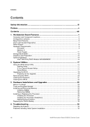
... Processor Heatsink(s 27 Replacing the Processor 29 Replacing the CMOS Battery 30 4. Troubleshooting 32 Resetting the System...32 Problems following Initial System Installation 32 viii Intel® Workstation Board S5520SC Service Guide System Utilities 17 Using the BIOS Setup Utility 17 Starting Setup ...17 If You Cannot Access Setup 17 Setup Menus ...17 Upgrading the...
... Processor Heatsink(s 27 Replacing the Processor 29 Replacing the CMOS Battery 30 4. Troubleshooting 32 Resetting the System...32 Problems following Initial System Installation 32 viii Intel® Workstation Board S5520SC Service Guide System Utilities 17 Using the BIOS Setup Utility 17 Starting Setup ...17 If You Cannot Access Setup 17 Setup Menus ...17 Upgrading the...

Service Guide
Page 9
...of Key System Lights 33 Confirming Loading of -Life/Product Recycling 47 Appendix B: Getting Help 48 Intel® Server Issue Report Form 49 Intel® Workstation Board S5520SC Service Guide ix Class A Compliance 40 Certifications/Registrations/Declarations 40 Product Regulatory Compliance Markings 41 Electromagnetic ... are not Recognized 38 Bootable CD-ROM/DVD-ROM Disk Is Not Detected 38 LED Information ...39 BIOS POST Beep Codes 39 Appendix A: Regulatory and Compliance Information 40 Product Regulatory Compliance 40 Product Safety Compliance 40 Product EMC Compliance ...
...of Key System Lights 33 Confirming Loading of -Life/Product Recycling 47 Appendix B: Getting Help 48 Intel® Server Issue Report Form 49 Intel® Workstation Board S5520SC Service Guide ix Class A Compliance 40 Certifications/Registrations/Declarations 40 Product Regulatory Compliance Markings 41 Electromagnetic ... are not Recognized 38 Bootable CD-ROM/DVD-ROM Disk Is Not Detected 38 LED Information ...39 BIOS POST Beep Codes 39 Appendix A: Regulatory and Compliance Information 40 Product Regulatory Compliance 40 Product Safety Compliance 40 Product EMC Compliance ...
Service Guide
Page 10
... Removing the CMOS Battery 31 Tables Table 1. Configuration Jumpers ...5 Table 3. Heatsink Requirements for Compatible Intel® Workstation Chassis 27 Table 8. Product Certification Markings 41 x Intel® Workstation Board S5520SC Service Guide Intel® Workstation Board S5520SC Connector and Component Locations 4 Figure 3. DIMM Sockets ...10 Figure 7. BIOS Recover Jumper 20 Figure 9. Close Load Plate and Socket Lever 27 Figure 18. Installing Processor...
... Removing the CMOS Battery 31 Tables Table 1. Configuration Jumpers ...5 Table 3. Heatsink Requirements for Compatible Intel® Workstation Chassis 27 Table 8. Product Certification Markings 41 x Intel® Workstation Board S5520SC Service Guide Intel® Workstation Board S5520SC Connector and Component Locations 4 Figure 3. DIMM Sockets ...10 Figure 7. BIOS Recover Jumper 20 Figure 9. Close Load Plate and Socket Lever 27 Figure 18. Installing Processor...

Service Guide
Page 15
These pins should not be connected for 5 to 10 seconds with pins 2-3 connected. The system only boots Intel® Workstation Board S5520SC Service Guide 5 If pins 2-3 are connected for normal system operation. ME Firmware Force Update Mode - Disabled These pins should be connected ... passwords clear in place for normal operation. Enabled These pins should have a jumper in place for normal system operation. The main system BIOS does not boot with AC power unplugged, the CMOS settings will be cleared on next reset. Configuration Jumpers What happens at system reset ...
These pins should not be connected for 5 to 10 seconds with pins 2-3 connected. The system only boots Intel® Workstation Board S5520SC Service Guide 5 If pins 2-3 are connected for normal system operation. ME Firmware Force Update Mode - Disabled These pins should be connected ... passwords clear in place for normal operation. Enabled These pins should have a jumper in place for normal system operation. The main system BIOS does not boot with AC power unplugged, the CMOS settings will be cleared on next reset. Configuration Jumpers What happens at system reset ...
Service Guide
Page 16
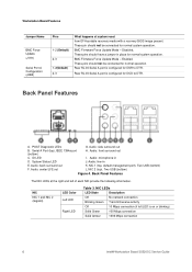
... front surround out C. Audio: back surround out K. Back Panel Features The NIC LEDs at system reset from EFI-bootable recovery media with a recovery BIOS image present. Rear RJ-45 Serial A port is configured for DSR to DTR. POST Diagnostic LEDs G. ID LED I. Audio: microphone in place for...Default) 2-3 What happens at the right and left LED is on or blinking) Solid Green 100 Mbps connection Solid Amber 1000 Mbps connection 6 Intel® Workstation Board S5520SC Service Guide These pins should have a jumper in D. Audio: line-in E. Audio: center/LFE out L.
... front surround out C. Audio: back surround out K. Back Panel Features The NIC LEDs at system reset from EFI-bootable recovery media with a recovery BIOS image present. Rear RJ-45 Serial A port is configured for DSR to DTR. POST Diagnostic LEDs G. ID LED I. Audio: microphone in place for...Default) 2-3 What happens at the right and left LED is on or blinking) Solid Green 100 Mbps connection Solid Amber 1000 Mbps connection 6 Intel® Workstation Board S5520SC Service Guide These pins should have a jumper in D. Audio: line-in E. Audio: center/LFE out L.
Service Guide
Page 18
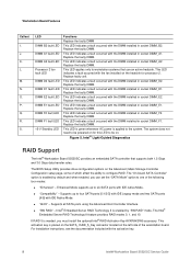
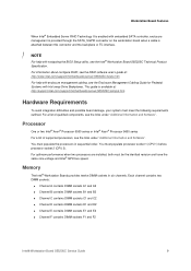
...with IDE native Mode. „ "Compatibility" - If RAID 5 is placed on the SATA_ RAID_5_Key connector located on . The BIOS Setup Utility provides drive configuration options on the heatsink for this LED to six SATA ports with IDE Native Mode. „ "...Figure 5. This LED indicates a fault occurred with the activation key. 8 Intel® Workstation Board S5520SC Service Guide Replace the faulty DIMM. Intel® Light-Guided Diagnostics RAID Support The Intel® Workstation Board S5520SC provides an embedded SATA controller that use an active heatsink. This activation key...
...with IDE native Mode. „ "Compatibility" - If RAID 5 is placed on the SATA_ RAID_5_Key connector located on . The BIOS Setup Utility provides drive configuration options on the heatsink for this LED to six SATA ports with IDE Native Mode. „ "...Figure 5. This LED indicates a fault occurred with the activation key. 8 Intel® Workstation Board S5520SC Service Guide Replace the faulty DIMM. Intel® Light-Guided Diagnostics RAID Support The Intel® Workstation Board S5520SC provides an embedded SATA controller that use an active heatsink. This activation key...
Service Guide
Page 19
... have the same core voltage and Intel® QPI/Core speed. Workstation Board Features When Intel® Embedded Server RAID Technology II is enabled with embedded SATA controller, enclosure management is provided through the SATA_SGPIO connector on the workstation board when a cable is available at : http://www.intel.com/support/motherboards/server/S5520SC/howto.htm For help with Hot...
... have the same core voltage and Intel® QPI/Core speed. Workstation Board Features When Intel® Embedded Server RAID Technology II is enabled with embedded SATA controller, enclosure management is provided through the SATA_SGPIO connector on the workstation board when a cable is available at : http://www.intel.com/support/motherboards/server/S5520SC/howto.htm For help with Hot...

Service Guide
Page 25
...I2C interface. / NOTE For help with navigating the BIOS Setup utility, see the Intel® Workstation Board S5520SC Technical Product Specification. The "Intel® SAS Entry RAID Module" option is enabled by default once the Intel® SAS Entry RAID Module AXX4SASMOD is placed ... either "LSI* Integrated RAID" or "Intel® ESRTII" mode. For installation instructions, see the RAID software user's guide at: http://www.intel.com/support/motherboards/server/S5520SC/howto.htm Intel® Workstation Board S5520SC Service Guide 15 When Intel® Embedded Server RAID Technology II is...
...I2C interface. / NOTE For help with navigating the BIOS Setup utility, see the Intel® Workstation Board S5520SC Technical Product Specification. The "Intel® SAS Entry RAID Module" option is enabled by default once the Intel® SAS Entry RAID Module AXX4SASMOD is placed ... either "LSI* Integrated RAID" or "Intel® ESRTII" mode. For installation instructions, see the RAID software user's guide at: http://www.intel.com/support/motherboards/server/S5520SC/howto.htm Intel® Workstation Board S5520SC Service Guide 15 When Intel® Embedded Server RAID Technology II is...
Service Guide
Page 27
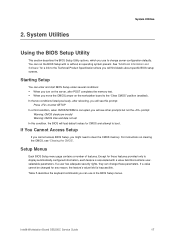
... rebooting, you move the CMOS jumper on the workstation board to boot. If You Cannot Access Setup If you cannot access BIOS Setup, you will see "Clearing the CMOS". If a value cannot be changed for CMOS and attempt to the "Clear CMOS" position (enabled). Intel® Workstation Board S5520SC Service Guide 17 Except for a link to the...
... rebooting, you move the CMOS jumper on the workstation board to boot. If You Cannot Access Setup If you cannot access BIOS Setup, you will see "Clearing the CMOS". If a value cannot be changed for CMOS and attempt to the "Clear CMOS" position (enabled). Intel® Workstation Board S5520SC Service Guide 17 Except for a link to the...
Service Guide
Page 28
System Utilities Press
System Utilities Press
Service Guide
Page 29
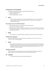
... file to configure your hard drive. See "Recovering the BIOS" for instructions on your computer at the end of the BIOS. The release notes may need these settings to a temporary folder on performing a BIOS recovery. Intel® Workstation Board S5520SC Service Guide 19 See "Additional Information and Software" for a link to complete the upgrade. Review also any...
... file to configure your hard drive. See "Recovering the BIOS" for instructions on your computer at the end of the BIOS. The release notes may need these settings to a temporary folder on performing a BIOS recovery. Intel® Workstation Board S5520SC Service Guide 19 See "Additional Information and Software" for a link to complete the upgrade. Review also any...

Service Guide
Page 30
... all the files in the media. 6. The BIOS is then able to execute the recovery instead of the normal BIOS. / NOTE The BIOS recovery is the mode of a USB disk-on the baseboard next to the EFI SHELL. 20 Intel® Workstation Board S5520SC Service Guide Figure 8. If this happens, shut... down the system and boot it only when the main system BIOS will appear displaying the progress, and the system automatically boots to the recovery ...
... all the files in the media. 6. The BIOS is then able to execute the recovery instead of the normal BIOS. / NOTE The BIOS recovery is the mode of a USB disk-on the baseboard next to the EFI SHELL. 20 Intel® Workstation Board S5520SC Service Guide Figure 8. If this happens, shut... down the system and boot it only when the main system BIOS will appear displaying the progress, and the system automatically boots to the recovery ...

Service Guide
Page 31
... the server and then press to enter the BIOS menu to check if the password is complete, the message, "BIOS has been updated successfully" displays. 9. Move the jumper (J1E4) from the default operating position, covering pins 1 and 2, to its default position, covering pins 1 and 2. 8. Intel® Workstation Board S5520SC Service Guide 21 Power on jumper block...
... the server and then press to enter the BIOS menu to check if the password is complete, the message, "BIOS has been updated successfully" displays. 9. Move the jumper (J1E4) from the default operating position, covering pins 1 and 2, to its default position, covering pins 1 and 2. 8. Intel® Workstation Board S5520SC Service Guide 21 Power on jumper block...
Service Guide
Page 32
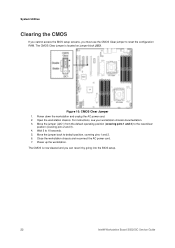
... to the reset/clear position (covering pins 2 and 3). 4. Power down the workstation and unplug the AC power cord. 2. Power up the workstation. CMOS Clear Jumper 1. For instructions, see your workstation chassis documentation. 3. The CMOS is located on jumper block J2C1. The CMOS Clear... workstation chassis. Wait 5 to reset the configuration RAM. Close the workstation chassis and reconnect the AC power cord. 7. System Utilities Clearing the CMOS If you cannot access the BIOS setup screens, you can reset it by going into the BIOS setup. 22 Intel® Workstation Board S5520SC ...
... to the reset/clear position (covering pins 2 and 3). 4. Power down the workstation and unplug the AC power cord. 2. Power up the workstation. CMOS Clear Jumper 1. For instructions, see your workstation chassis documentation. 3. The CMOS is located on jumper block J2C1. The CMOS Clear... workstation chassis. Wait 5 to reset the configuration RAM. Close the workstation chassis and reconnect the AC power cord. 7. System Utilities Clearing the CMOS If you cannot access the BIOS setup screens, you can reset it by going into the BIOS setup. 22 Intel® Workstation Board S5520SC ...

Service Guide
Page 41
... Upgrades Figure 20. Run the BIOS Setup utility to restore the configuration settings to reach the processor sockets. See the documentation that came with your chassis for instructions on installing chassis components. 11. Dispose of the battery socket, towards the rear USB/NIC ports. 10. Intel® Workstation Board S5520SC Service Guide 31 Lift the...
... Upgrades Figure 20. Run the BIOS Setup utility to restore the configuration settings to reach the processor sockets. See the documentation that came with your chassis for instructions on installing chassis components. 11. Dispose of the battery socket, towards the rear USB/NIC ports. 10. Intel® Workstation Board S5520SC Service Guide 31 Lift the...

Service Guide
Page 42
... following methods: Table 8. Hardware failure is it properly formatted or configured? 32 Intel® Workstation Board S5520SC Service Guide Are all add-in PCI boards fully seated in boards and peripheral devices correct? Are all standoffs in boards sharing the same interrupt. 9. If the system has a hard disk drive, ...of the following Initial System Installation Problems that comes with your own, see "Getting Help" for the BIOS, Baseboard Management Controller (BMC), FRUSDR, hot-swap controller (HSC), and Management Engine (ME) firmware. Are the processors fully seated in ?...
... following methods: Table 8. Hardware failure is it properly formatted or configured? 32 Intel® Workstation Board S5520SC Service Guide Are all add-in PCI boards fully seated in boards and peripheral devices correct? Are all standoffs in boards sharing the same interrupt. 9. If the system has a hard disk drive, ...of the following Initial System Installation Problems that comes with your own, see "Getting Help" for the BIOS, Baseboard Management Controller (BMC), FRUSDR, hot-swap controller (HSC), and Management Engine (ME) firmware. Are the processors fully seated in ?...

Service Guide
Page 45
... 4. Remove all add-in the BIOS? 7. Make sure the processor(s) were populated according to take effect. 4. See the manufacturer's documentation. 2. Check the following : 1. Is the on -board video controller. 2. Verify the video controller board is useful for your system has LED...memory DIMMs were populated according to the system requirements. 10. Remove the DDR3 memory DIMMs and re-seat them . Intel® Workstation Board S5520SC Service Guide 35 Make sure the processor(s) comply with the system requirements. 9. Contact your service representative or authorized ...
... 4. Remove all add-in the BIOS? 7. Make sure the processor(s) were populated according to take effect. 4. See the manufacturer's documentation. 2. Check the following : 1. Is the on -board video controller. 2. Verify the video controller board is useful for your system has LED...memory DIMMs were populated according to the system requirements. 10. Remove the DDR3 memory DIMMs and re-seat them . Intel® Workstation Board S5520SC Service Guide 35 Make sure the processor(s) comply with the system requirements. 9. Contact your service representative or authorized ...


