
Product Guide
Page 3
...Board Features 9 Server Board Connector and Component Locations 11 Back Panel Connectors 12 Front Panel Connectors 12 Processor ...13 Memory ...13 Intel 875P Chipset...14 Intel 82875P Memory Controller Hub (MCH 14 Intel 82801EB I/O Controller Hub (ICH5-R 15 Intel 82802AC Firmware Hub (FWH 15 Video ...15 AGP Connector ...16...Support...19 PCI I/O Subsystem...20 32-bit, 33-MHz PCI Subsystem 20 Device IDs (IDSEL 21 Data Storage ...21 Serial ATA (SATA) ...21 IDE Interfaces ...22 SCSI Hard Drive Activity LED Connector 22 Network Interface Controller (NIC 23 NIC Connector and Status LEDs 23...
...Board Features 9 Server Board Connector and Component Locations 11 Back Panel Connectors 12 Front Panel Connectors 12 Processor ...13 Memory ...13 Intel 875P Chipset...14 Intel 82875P Memory Controller Hub (MCH 14 Intel 82801EB I/O Controller Hub (ICH5-R 15 Intel 82802AC Firmware Hub (FWH 15 Video ...15 AGP Connector ...16...Support...19 PCI I/O Subsystem...20 32-bit, 33-MHz PCI Subsystem 20 Device IDs (IDSEL 21 Data Storage ...21 Serial ATA (SATA) ...21 IDE Interfaces ...22 SCSI Hard Drive Activity LED Connector 22 Network Interface Controller (NIC 23 NIC Connector and Status LEDs 23...
Product Guide
Page 4
... Network Boot 35 Booting Without Attached Devices 36 Fast Booting Systems with Intel® Rapid BIOS Boot 36 Intel Rapid BIOS Boot 36 System Management BIOS (SMBIOS 37 2 Server Board...Warnings and Cautions...39 Installing the I/O Shield ...41 Installing Chassis Standoffs 42 Intel Server Chassis SC5200 42 Intel® Server Chassis SC5250-E 43 Installing the Server Board...44 Placing the ... Connecting the Serial ATA Cable (Optional 54 Connecting Internal Headers 55 Connecting the Front Panel Header 55 Connecting the USB 2.0 Header 56 Connecting Hardware Control and Power Cables 57...
... Network Boot 35 Booting Without Attached Devices 36 Fast Booting Systems with Intel® Rapid BIOS Boot 36 Intel Rapid BIOS Boot 36 System Management BIOS (SMBIOS 37 2 Server Board...Warnings and Cautions...39 Installing the I/O Shield ...41 Installing Chassis Standoffs 42 Intel Server Chassis SC5200 42 Intel® Server Chassis SC5250-E 43 Installing the Server Board...44 Placing the ... Connecting the Serial ATA Cable (Optional 54 Connecting Internal Headers 55 Connecting the Front Panel Header 55 Connecting the USB 2.0 Header 56 Connecting Hardware Control and Power Cables 57...

Product Guide
Page 7
...Jumper Block Location 58 Figure 23. Table 2. Table 8. Table 10. Table 13. Table 17. Connecting the IDE Cable 53 Figure 19. Connecting the SATA Cable 54 Figure 20. Table 3. Table 9. Table 12. Attaching the Fan Heat Sink Clips to the Processor Socket 47 Figure 14. Location of Pressing... the Power Switch under ACPI 25 Wake-up Devices and Events 26 Fan Connector Function/Operation 28 Supervisor and User Password Functions 31 Front Panel Header (J7J1 55 USB 2.0 Header (J7E1 56 Jumper Settings for the BIOS Setup Program Modes (J8J2 59 BIOS Setup Program Menu Bar...
...Jumper Block Location 58 Figure 23. Table 2. Table 8. Table 10. Table 13. Table 17. Connecting the IDE Cable 53 Figure 19. Connecting the SATA Cable 54 Figure 20. Table 3. Table 9. Table 12. Attaching the Fan Heat Sink Clips to the Processor Socket 47 Figure 14. Location of Pressing... the Power Switch under ACPI 25 Wake-up Devices and Events 26 Fan Connector Function/Operation 28 Supervisor and User Password Functions 31 Front Panel Header (J7J1 55 USB 2.0 Header (J7E1 56 Jumper Settings for the BIOS Setup Program Modes (J8J2 59 BIOS Setup Program Menu Bar...

Product Guide
Page 9
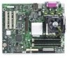
...SATA-150 controller, Promise Technology* PDC20319 • Accelerated Graphics Port (AGP) connector providing AGP 8x support continued 9 Table 1. ATI Rage* XL Video Controller with 8 MB of Intel® Server Board S875WP1-E. Support for RAID... 0 and 1 support is available in an mPGA478 package with an 800/533/400 MHz system bus Memory • Four 184-pin DDR ...• Intel® 82875P Memory Controller Hub (MCH) • Intel® 82801EB I /O controller Peripheral Interfaces • Four external USB ports on the back panel with an...
...SATA-150 controller, Promise Technology* PDC20319 • Accelerated Graphics Port (AGP) connector providing AGP 8x support continued 9 Table 1. ATI Rage* XL Video Controller with 8 MB of Intel® Server Board S875WP1-E. Support for RAID... 0 and 1 support is available in an mPGA478 package with an 800/533/400 MHz system bus Memory • Four 184-pin DDR ...• Intel® 82875P Memory Controller Hub (MCH) • Intel® 82801EB I /O controller Peripheral Interfaces • Four external USB ports on the back panel with an...
Product Guide
Page 10
...on USB, PCI, RS-232, PS/2, LAN, and front panel Hardware Management Hardware monitor with: • Four fan sensing inputs used to monitor fan activity • Remote diode temperature sensing • Intel® Precision Cooling Technology fan speed control that automatically adjusts ...chassis fan speeds based on system temperature • Voltage sensing to detect out of range values 10 Intel Server Board S875WP1-E Product Guide
...on USB, PCI, RS-232, PS/2, LAN, and front panel Hardware Management Hardware monitor with: • Four fan sensing inputs used to monitor fan activity • Remote diode temperature sensing • Intel® Precision Cooling Technology fan speed control that automatically adjusts ...chassis fan speeds based on system temperature • Voltage sensing to detect out of range values 10 Intel Server Board S875WP1-E Product Guide

Product Guide
Page 11
... C D E FG CC H BB I . Battery RQ TP00182 B. +12V CPU Power Connector C. DIMM Sockets F. System Fan 1 Header M. System Fan 2 Header N. BIOS Configuration Jumper (J8J2) P. SCSI LED Header S. SATA-A1 through SATA-A4 Connector (S875WP1LX only, from left to right: SATA-A4, SATA-A2, SATA-A3, SATA-A1) T. AGP Connector AA. Back Panel I/O Ports Q. Hot Swap Backplane Header Figure 1.
... C D E FG CC H BB I . Battery RQ TP00182 B. +12V CPU Power Connector C. DIMM Sockets F. System Fan 1 Header M. System Fan 2 Header N. BIOS Configuration Jumper (J8J2) P. SCSI LED Header S. SATA-A1 through SATA-A4 Connector (S875WP1LX only, from left to right: SATA-A4, SATA-A2, SATA-A3, SATA-A1) T. AGP Connector AA. Back Panel I/O Ports Q. Hot Swap Backplane Header Figure 1.

Product Guide
Page 12
Serial port A I. USB ports 3 and 4 E. SCSI LED Header B. Front Panel Header Figure 3. PS/2 keyboard G. Back Panel Connectors Front Panel Connectors Figure 3 shows the location of the front panel connectors. PS/2 mouse F. TP00183 A B A. Front Panel Connectors TP00184 12 Video port Figure 2. Back Panel Connectors The back panel connectors are color-coded in compliance with PC 99 recommendations. Parallel port H. NIC 1 (1 Gb) B. C F G A B D E HI A. USB ports 1 and 2 D. NIC 2 (10/100 Mb) C.
Serial port A I. USB ports 3 and 4 E. SCSI LED Header B. Front Panel Header Figure 3. PS/2 keyboard G. Back Panel Connectors Front Panel Connectors Figure 3 shows the location of the front panel connectors. PS/2 mouse F. TP00183 A B A. Front Panel Connectors TP00184 12 Video port Figure 2. Back Panel Connectors The back panel connectors are color-coded in compliance with PC 99 recommendations. Parallel port H. NIC 1 (1 Gb) B. C F G A B D E HI A. USB ports 1 and 2 D. NIC 2 (10/100 Mb) C.
Product Guide
Page 18
... before a keyboard or mouse is connected or disconnected. The serial port A connector is located on the back panel. Serial Port The server board S875WP1-E has one serial port connector and one diskette drive that , like a self-healing fuse, reestablishes the connection... after an overcurrent condition is removed. ✏ NOTE The keyboard is supported in the bottom PS/2 connector and the mouse is supported in the BIOS Setup program. 18 Intel Server Board S875WP1...
... before a keyboard or mouse is connected or disconnected. The serial port A connector is located on the back panel. Serial Port The server board S875WP1-E has one serial port connector and one diskette drive that , like a self-healing fuse, reestablishes the connection... after an overcurrent condition is removed. ✏ NOTE The keyboard is supported in the bottom PS/2 connector and the mouse is supported in the BIOS Setup program. 18 Intel Server Board S875WP1...
Product Guide
Page 19
...USB. USB devices are routed to operating system and driver initialization. Four ports are limited to USB 1.1 transfer rates prior to the back panel. USB 2.0 support requires both an operating system and drivers that meets the requirements for a full-speed USB device. By default, Legacy ...not meet FCC Class B requirements, even if no device or a lowspeed USB device is set to the front panel. Legacy USB support is attached to USB 1.1 operation. The S875WP1-E server board fully supports UHCI and uses UHCI-compatible software drivers. ✏ NOTE Computer systems that do not support...
...USB. USB devices are routed to operating system and driver initialization. Four ports are limited to USB 1.1 transfer rates prior to the back panel. USB 2.0 support requires both an operating system and drivers that meets the requirements for a full-speed USB device. By default, Legacy ...not meet FCC Class B requirements, even if no device or a lowspeed USB device is set to the front panel. Legacy USB support is attached to USB 1.1 operation. The S875WP1-E server board fully supports UHCI and uses UHCI-compatible software drivers. ✏ NOTE Computer systems that do not support...

Product Guide
Page 25
... - No context will be lost in this state... Pressing the power button or another wake-up events • Support for a front panel power and sleep mode switch The Server Board S875WP1-E supports sleep states S0, S1, S2, S3, S4, and S5. CAUTION The system is off only when the AC power is...
... - No context will be lost in this state... Pressing the power button or another wake-up events • Support for a front panel power and sleep mode switch The Server Board S875WP1-E supports sleep states S0, S1, S2, S3, S4, and S5. CAUTION The system is off only when the AC power is...
Product Guide
Page 26
...alarm LAN PCI via PME# Wake-up Support When the PME# signal on the PCI bus is disabled by default in BIOS). 26 Intel Server Board S875WP1-E Product Guide In addition, software, drivers, and peripherals must be capable of these wake-up events from an ACPI state requires an...capabilities, the 5 V standby line for PCI 2.2 compliant LAN designs • The onboard LAN subsystem PCI via PME# signal Resume on Ring (back panel Serial Port A) USB PS/2 ...from this option to provide adequate standby current when implementing LAN wake capabilities can wake the computer from specific states.
...alarm LAN PCI via PME# Wake-up Support When the PME# signal on the PCI bus is disabled by default in BIOS). 26 Intel Server Board S875WP1-E Product Guide In addition, software, drivers, and peripherals must be capable of these wake-up events from an ACPI state requires an...capabilities, the 5 V standby line for PCI 2.2 compliant LAN designs • The onboard LAN subsystem PCI via PME# signal Resume on Ring (back panel Serial Port A) USB PS/2 ...from this option to provide adequate standby current when implementing LAN wake capabilities can wake the computer from specific states.

Product Guide
Page 52
... to release the retention pin from the server board: 1. Pull back on the lever that secures the card's metal bracket to the chassis back panel. 3. A Figure 17. Installing the AGP Card TP00191 Removing the AGP Card Follow these instructions to install an AGP card: 1. Observe the precautions... in "Before You Begin" on the card until it from the socket. 52 Intel Server Board S875WP1-E Product Guide Remove the screw that is fully seated in the AGP connector. Observe the precautions in "Before You Begin" on the ...
... to release the retention pin from the server board: 1. Pull back on the lever that secures the card's metal bracket to the chassis back panel. 3. A Figure 17. Installing the AGP Card TP00191 Removing the AGP Card Follow these instructions to install an AGP card: 1. Observe the precautions... in "Before You Begin" on the card until it from the socket. 52 Intel Server Board S875WP1-E Product Guide Remove the screw that is fully seated in the AGP connector. Observe the precautions in "Before You Begin" on the ...

Product Guide
Page 55
... 39. B 1 2 A2 10 1 9 A Front Panel USB 2.0 Header B Front Panel Header Figure 20. Figure 20 (above) shows the location of Internal Headers 33 34 TP00194 Connecting the Front Panel Header Before connecting the front panel header, observe the precautions in "Before You Begin" on ...page 39. Front Panel Header (J7J1) Pin Signal Name Pin(s) 1 Power LED Anode 2 3 Key 4 5 ...
... 39. B 1 2 A2 10 1 9 A Front Panel USB 2.0 Header B Front Panel Header Figure 20. Figure 20 (above) shows the location of Internal Headers 33 34 TP00194 Connecting the Front Panel Header Before connecting the front panel header, observe the precautions in "Before You Begin" on ...page 39. Front Panel Header (J7J1) Pin Signal Name Pin(s) 1 Power LED Anode 2 3 Key 4 5 ...

Product Guide
Page 56
Table 12. Front Panel Header (J7J1) (continued) 19 ACPI Sleep Switch 20 Chassis Intrusion 21 GND (ACPI Sleep Switch 22 NIC#2 Activity LED Anode 23 Unused 24 NIC#2 Activity ... 2.0 Header Before connecting the USB 2.0 header, observe the precautions in "Before You Begin" on page 39. Table 13 shows the pin assignments for the front panel header. USB 2.0 Header (J7E1) Pin Signal name 1 USB_FNT1_PWR 3 USB_FRONT1_L* 5 USB_ FRONT1_L 7 Ground 9 Key Note: USB ports may be assigned as needed. Pin Signal name 2 USB_FNT1_PWR...
Table 12. Front Panel Header (J7J1) (continued) 19 ACPI Sleep Switch 20 Chassis Intrusion 21 GND (ACPI Sleep Switch 22 NIC#2 Activity LED Anode 23 Unused 24 NIC#2 Activity ... 2.0 Header Before connecting the USB 2.0 header, observe the precautions in "Before You Begin" on page 39. Table 13 shows the pin assignments for the front panel header. USB 2.0 Header (J7E1) Pin Signal name 1 USB_FNT1_PWR 3 USB_FRONT1_L* 5 USB_ FRONT1_L 7 Ground 9 Key Note: USB ports may be assigned as needed. Pin Signal name 2 USB_FNT1_PWR...

Product Guide
Page 101
... the server chassis. Plug the power cables into the pin 1 end of the baseboard and front panel connectors provide operating voltage (+5 V DC and +12 V DC, for powering devices external to power the server board S875WP1-E. Technical Reference 101 These connectors are not overcurrent protected. Do not use these connectors for example) to...
... the server chassis. Plug the power cables into the pin 1 end of the baseboard and front panel connectors provide operating voltage (+5 V DC and +12 V DC, for powering devices external to power the server board S875WP1-E. Technical Reference 101 These connectors are not overcurrent protected. Do not use these connectors for example) to...


