
Installation Guide
Page 1
Intel® SC5100 and SC5200 Rack Kit Installation Guide Order Number: A58842-005
Intel® SC5100 and SC5200 Rack Kit Installation Guide Order Number: A58842-005
Installation Guide
Page 4
Installing the Server into a Rack 32 iv Intel SC5100 and SC5200 Rack Kit Installation Guide Installing the Top Cover 29 19. Rails Installed in a Rack 31 23. Removing the Smallest Rail 30 21. Installing the Front Cover 28 18. Installing the Handles 30 20. Attaching the Rail to the Chassis 31 22. Installing the Screw Plate 27 17. 15. Installing the Bezel...26 16.
Installing the Server into a Rack 32 iv Intel SC5100 and SC5200 Rack Kit Installation Guide Installing the Top Cover 29 19. Rails Installed in a Rack 31 23. Removing the Smallest Rail 30 21. Installing the Front Cover 28 18. Installing the Handles 30 20. Attaching the Rail to the Chassis 31 22. Installing the Screw Plate 27 17. 15. Installing the Bezel...26 16.
Installation Guide
Page 5
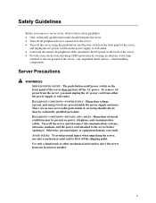
...energy levels are no user-serviceable parts inside the power supply enclosure. HAZARDOUS CONDITIONS-DEVICES AND CABLES: Hazardous electrical conditions may be done by wearing an antistatic wrist strap attached to chassis ground of the server does not turn off the AC power. Otherwise, personal ...unplug the AC power cord from either the power supply or wall outlet. To remove AC power from the server, you remove a server cover, observe these safety guidelines: • Only technically qualified personnel should only be present on the front panel of the server-any unpainted ...
...energy levels are no user-serviceable parts inside the power supply enclosure. HAZARDOUS CONDITIONS-DEVICES AND CABLES: Hazardous electrical conditions may be done by wearing an antistatic wrist strap attached to chassis ground of the server does not turn off the AC power. Otherwise, personal ...unplug the AC power cord from either the power supply or wall outlet. To remove AC power from the server, you remove a server cover, observe these safety guidelines: • Only technically qualified personnel should only be present on the front panel of the server-any unpainted ...
Installation Guide
Page 6
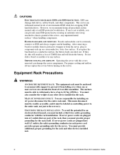
... the battery. If server power cords are plugged into AC outlets that are plugged into wall AC outlets, the safety grounding conductor in boards, and other device installed in a loss of environmental ESD while hot-swapping SCSI hard disk drives. However, we recommend doing all procedures in it must be anchored to an unmovable support to chassis ground of any...
... the battery. If server power cords are plugged into AC outlets that are plugged into wall AC outlets, the safety grounding conductor in boards, and other device installed in a loss of environmental ESD while hot-swapping SCSI hard disk drives. However, we recommend doing all procedures in it must be anchored to an unmovable support to chassis ground of any...

Installation Guide
Page 8
8 Intel SC5100 and SC5200 Rack Kit Installation Guide
8 Intel SC5100 and SC5200 Rack Kit Installation Guide
Installation Guide
Page 9
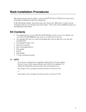
...-310-d rack standard. For additional compatibility and rack cabinet selection information, see http://support.intel.com/support/motherboards/server/chassis/sc5100 or http://support.intel.com/support/motherboards/server/chassis/sc5200 9 Kit Contents • Two unpainted access covers (SC5100 and SC5200 Base use the access cover without a fan access door; Rack Installation Procedures This manual describes the procedure to convert an Intel® SC5100 or SC5200 server chassis from the pedestal configuration to a chassis in rack orientation...
...-310-d rack standard. For additional compatibility and rack cabinet selection information, see http://support.intel.com/support/motherboards/server/chassis/sc5100 or http://support.intel.com/support/motherboards/server/chassis/sc5200 9 Kit Contents • Two unpainted access covers (SC5100 and SC5200 Base use the access cover without a fan access door; Rack Installation Procedures This manual describes the procedure to convert an Intel® SC5100 or SC5200 server chassis from the pedestal configuration to a chassis in rack orientation...

Installation Guide
Page 10
B C A A. Feet C. Figure 1. Workbench B. Remove Feet 1. Remove the four screws that hold the front foot to the chassis and remove the foot. 3. Place the chassis on a workbench so the feet hang over the side. 2. Removing the Feet OM12024 10 Intel SC5100 and SC5200 Rack Kit Installation Guide Remove the four screws that attach the rear foot to the chassis and remove the foot. Screw * Some chassis details shown may different in your chassis.
B C A A. Feet C. Figure 1. Workbench B. Remove Feet 1. Remove the four screws that hold the front foot to the chassis and remove the foot. 3. Place the chassis on a workbench so the feet hang over the side. 2. Removing the Feet OM12024 10 Intel SC5100 and SC5200 Rack Kit Installation Guide Remove the four screws that attach the rear foot to the chassis and remove the foot. Screw * Some chassis details shown may different in your chassis.

Installation Guide
Page 12
Power cable Figure 3. Disconnect the data and power cables from the device. 2. Remove and save the two screws that hold the slide rails to the chassis. D C B A A. 5 ¼-inch device B. Data cable D. Screw C. Removing a 5 ¼-Inch Device OM13721 12 Intel SC5100 and SC5200 Rack Kit Installation Guide Remove 5 ¼-Inch Devices 1.
Power cable Figure 3. Disconnect the data and power cables from the device. 2. Remove and save the two screws that hold the slide rails to the chassis. D C B A A. 5 ¼-inch device B. Data cable D. Screw C. Removing a 5 ¼-Inch Device OM13721 12 Intel SC5100 and SC5200 Rack Kit Installation Guide Remove 5 ¼-Inch Devices 1.
Installation Guide
Page 14
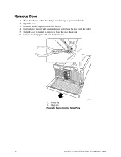
Remove the hinge pins and save for future use. Hinge pin Figure 5. Removing the Hinge Pins OM13729 14 Intel SC5100 and SC5200 Rack Kit Installation Guide Open the door. 3. Pull the hinge pin out with one hand while supporting the door with the other hinge pin. 6. Remove Door 1. Slide the door to the left to remove it from the other . 5. AB A. Press the plastic clip in towards the chassis. 4. Plastic clip B. Move the chassis so the door hangs over the edge of your workbench. 2.
Remove the hinge pins and save for future use. Hinge pin Figure 5. Removing the Hinge Pins OM13729 14 Intel SC5100 and SC5200 Rack Kit Installation Guide Open the door. 3. Pull the hinge pin out with one hand while supporting the door with the other hinge pin. 6. Remove Door 1. Slide the door to the left to remove it from the other . 5. AB A. Press the plastic clip in towards the chassis. 4. Plastic clip B. Move the chassis so the door hangs over the edge of your workbench. 2.
Installation Guide
Page 16
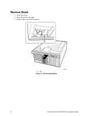
Press the tab up. 2. Remove the bezel from the chassis. Tab Figure 7. A A. Slide the bezel to the right. 3. Removing the Bezel OM13724 16 Intel SC5100 and SC5200 Rack Kit Installation Guide Remove Bezel 1.
Press the tab up. 2. Remove the bezel from the chassis. Tab Figure 7. A A. Slide the bezel to the right. 3. Removing the Bezel OM13724 16 Intel SC5100 and SC5200 Rack Kit Installation Guide Remove Bezel 1.

Installation Guide
Page 18
Remove and save the black clip. 4. Slide the cover backwards and remove it. Remove Side Covers Remove the Right Side Cover 1. C B A D A. Remove the clip D. Slide the cover off Figure 9. Pull up C. Remove and save the screw at the rear of the chassis. 2. Pull the clip up on the black clip. 3. Screw B. Removing the Right Side Cover OM13725 18 Intel SC5100 and SC5200 Rack Kit Installation Guide
Remove and save the black clip. 4. Slide the cover backwards and remove it. Remove Side Covers Remove the Right Side Cover 1. C B A D A. Remove the clip D. Slide the cover off Figure 9. Pull up C. Remove and save the screw at the rear of the chassis. 2. Pull the clip up on the black clip. 3. Screw B. Removing the Right Side Cover OM13725 18 Intel SC5100 and SC5200 Rack Kit Installation Guide
Installation Guide
Page 20
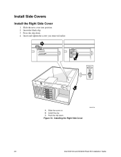
Press the clip down Figure 10. Slide the cover on B. Insert and tighten the screw you removed earlier. Push the clip down . 4. Installing the Right Side Cover OM13726 20 Intel SC5100 and SC5200 Rack Kit Installation Guide B C A A A. Insert the black clip. 3. Install the clip C. Install Side Covers Install the Right Side Cover 1. Slide the new cover into position. 2.
Press the clip down Figure 10. Slide the cover on B. Insert and tighten the screw you removed earlier. Push the clip down . 4. Installing the Right Side Cover OM13726 20 Intel SC5100 and SC5200 Rack Kit Installation Guide B C A A A. Insert the black clip. 3. Install the clip C. Install Side Covers Install the Right Side Cover 1. Slide the new cover into position. 2.
Installation Guide
Page 21
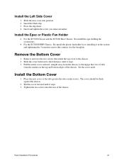
...you removed earlier. Set the cover aside. Install the Left Side Cover 1. Install the Epac or Plastic Fan Holder • For the SC5100 Chassis and the SC5200 Base Chassis: Re-install the epac holding the system fans. • For the SC5200 HSRP Chassis: Re-install the plastic fan holder by re-installing ... the chassis. 2. The cover should be flush against the chassis. 2. Insert the black clip. 3. Remove the Bottom Cover 1. Slid the cover forward until it stops. 3. Slide the new cover into the slots on the server. Press the clip down. 4. Rack Installation Procedures ...
...you removed earlier. Set the cover aside. Install the Left Side Cover 1. Install the Epac or Plastic Fan Holder • For the SC5100 Chassis and the SC5200 Base Chassis: Re-install the epac holding the system fans. • For the SC5200 HSRP Chassis: Re-install the plastic fan holder by re-installing ... the chassis. 2. The cover should be flush against the chassis. 2. Insert the black clip. 3. Remove the Bottom Cover 1. Slid the cover forward until it stops. 3. Slide the new cover into the slots on the server. Press the clip down. 4. Rack Installation Procedures ...

Installation Guide
Page 22
Screws that hold the EMI shields Figure 11. Remove the EMI shield. 3. Insert and tighten the four screws removed when you removed the slide rails. Installing 5 ¼-Inch Devices OM12029 22 Intel SC5100 and SC5200 Rack Kit Installation Guide EMI shields D. Slide the device into the Reorientation Bracket 1. Install 5 ¼-Inch Devices into the bracket. 4. Screws that hold the EMI shield in place. 2. Remove the two screws that hold the device C. B A C D A. 5 ¼-inch device B.
Screws that hold the EMI shields Figure 11. Remove the EMI shield. 3. Insert and tighten the four screws removed when you removed the slide rails. Installing 5 ¼-Inch Devices OM12029 22 Intel SC5100 and SC5200 Rack Kit Installation Guide EMI shields D. Slide the device into the Reorientation Bracket 1. Install 5 ¼-Inch Devices into the bracket. 4. Screws that hold the EMI shield in place. 2. Remove the two screws that hold the device C. B A C D A. 5 ¼-inch device B.

Installation Guide
Page 24
C A B D OM13730 A. Philips screwdriver B. Chassis intrusion switch Figure 13. Chassis intrusion switch lock C. Direction of rotation D. Using a Philips† screwdriver, rotate the switch lock ½ turn clockwise. Installing the Chassis Intrusion Lock 24 Intel SC5100 and SC5200 Rack Kit Installation Guide Install Bezel 1. Position the chassis intrusion switch lock. 2.
C A B D OM13730 A. Philips screwdriver B. Chassis intrusion switch Figure 13. Chassis intrusion switch lock C. Direction of rotation D. Using a Philips† screwdriver, rotate the switch lock ½ turn clockwise. Installing the Chassis Intrusion Lock 24 Intel SC5100 and SC5200 Rack Kit Installation Guide Install Bezel 1. Position the chassis intrusion switch lock. 2.

Installation Guide
Page 26
Slide it to the left until the tab locks in place. 4. A A. Installing the Bezel OM13724 26 Intel SC5100 and SC5200 Rack Kit Installation Guide Position the bezel. Tab Figure 15. Make sure all of the plastic tabs are aligned with their holes. 5.
Slide it to the left until the tab locks in place. 4. A A. Installing the Bezel OM13724 26 Intel SC5100 and SC5200 Rack Kit Installation Guide Position the bezel. Tab Figure 15. Make sure all of the plastic tabs are aligned with their holes. 5.

Installation Guide
Page 28
Installing the Front Cover OM13731 28 Intel SC5100 and SC5200 Rack Kit Installation Guide Tighten the thumbscrews. If you have a hot swap bay installed, remove that plastic cover. 3. Install Front Cover 1. Position the bezel by sliding the tabs on the top under the bezel. 4. Figure 17. For each 5 ¼-inch peripheral, remove the corresponding plastic cover. 2.
Installing the Front Cover OM13731 28 Intel SC5100 and SC5200 Rack Kit Installation Guide Tighten the thumbscrews. If you have a hot swap bay installed, remove that plastic cover. 3. Install Front Cover 1. Position the bezel by sliding the tabs on the top under the bezel. 4. Figure 17. For each 5 ¼-inch peripheral, remove the corresponding plastic cover. 2.
Installation Guide
Page 29
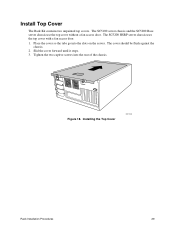
The SC5100 server chassis and the SC5200 Base server chassis use the top cover without a fan access door. Slid the cover forward until it stops. 3. The SC5200 HSRP server chassis uses the top cover with a fan access door. 1. The cover should be flush against the chassis. 2. Install Top Cover The Rack Kit contains two unpainted top covers. Tighten the two captive screws into the slots on the server. Installing the Top Cover OM11928 Rack Installation Procedures 29 Figure 18. Place the cover so the tabs go into the rear of the chassis.
The SC5100 server chassis and the SC5200 Base server chassis use the top cover without a fan access door. Slid the cover forward until it stops. 3. The SC5200 HSRP server chassis uses the top cover with a fan access door. 1. The cover should be flush against the chassis. 2. Install Top Cover The Rack Kit contains two unpainted top covers. Tighten the two captive screws into the slots on the server. Installing the Top Cover OM11928 Rack Installation Procedures 29 Figure 18. Place the cover so the tabs go into the rear of the chassis.
Installation Guide
Page 30
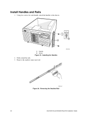
Using two screws for each handle, attach the handles to the chassis. Handle B. Installing the Handles 2. Fully extend the rails. 3. B A A. OM13733 OM12541 Figure 20. Removing the Smallest Rail 30 Intel SC5100 and SC5200 Rack Kit Installation Guide Remove the smallest, inner-most rail. Install Handles and Rails 1. Screw Figure 19.
Using two screws for each handle, attach the handles to the chassis. Handle B. Installing the Handles 2. Fully extend the rails. 3. B A A. OM13733 OM12541 Figure 20. Removing the Smallest Rail 30 Intel SC5100 and SC5200 Rack Kit Installation Guide Remove the smallest, inner-most rail. Install Handles and Rails 1. Screw Figure 19.
Installation Guide
Page 32
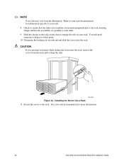
... chassis engage the rails in your rack documentation for more information. 32 Intel SC5100 and SC5200 Rack Kit Installation Guide CAUTION If you at this point. 10. OM13736 Figure 23. Secure the server to each rail and slide the server into the rack. Refer to your rack. See your rack. 8. Hold the chassis so the rails on each other. 9. Installing the Server into the rack, remove the server...
... chassis engage the rails in your rack documentation for more information. 32 Intel SC5100 and SC5200 Rack Kit Installation Guide CAUTION If you at this point. 10. OM13736 Figure 23. Secure the server to each rail and slide the server into the rack. Refer to your rack. See your rack. 8. Hold the chassis so the rails on each other. 9. Installing the Server into the rack, remove the server...
