Product Guide
Page 3
Contents 1 Description Server Board Features ...7 Server Board Connector and Component Locations 8 Back Panel Connectors 9 Processor ...10 Memory ...10 PCI Riser Slots ...10 Video ...11 SCSI Controller ...11 ATA-100 Controller...11 IDE RAID...Board Bumpers ...23 Install the Server Board ...24 Installing Processors ...25 Install the Processor Terminator 28 Memory ...29 Connect Cables...30 3 Upgrading Tools and Supplies Needed 31 Cautions ...31 Memory ...32 Processors ...33 Adding or Replacing a Processor 34 Removing a Processor 37 Installing and Removing a Terminator 38 Replacing the Back...
Contents 1 Description Server Board Features ...7 Server Board Connector and Component Locations 8 Back Panel Connectors 9 Processor ...10 Memory ...10 PCI Riser Slots ...10 Video ...11 SCSI Controller ...11 ATA-100 Controller...11 IDE RAID...Board Bumpers ...23 Install the Server Board ...24 Installing Processors ...25 Install the Processor Terminator 28 Memory ...29 Connect Cables...30 3 Upgrading Tools and Supplies Needed 31 Cautions ...31 Memory ...32 Processors ...33 Adding or Replacing a Processor 34 Removing a Processor 37 Installing and Removing a Terminator 38 Replacing the Back...
Product Guide
Page 6
... 102 13. Server Board Connector and Component Locations 8 2. J6A2 Jumper Block for DSR Signal 15 5. Installing the Server Board 24 9. Installing Processors...25 11. Closing the Locking Lever 27 13. Connecting Cables ...30 17. Attach the Heat Sink...36 21. System Setup Utility Main Window...36 22. J6A2 Jumper Block for DCD Signal 15 4. Insert the Processor and Lower the Locking Bar 34 19. Platform Event Action Dialogs 71 29. Server Board Features 7 3. Power Usage Worksheet 2 103 vi Intel Server Board SCB2 Product Guide Platform Event Paging Dialog 67 27. Hot ...
... 102 13. Server Board Connector and Component Locations 8 2. J6A2 Jumper Block for DSR Signal 15 5. Installing the Server Board 24 9. Installing Processors...25 11. Closing the Locking Lever 27 13. Connecting Cables ...30 17. Attach the Heat Sink...36 21. System Setup Utility Main Window...36 22. J6A2 Jumper Block for DCD Signal 15 4. Insert the Processor and Lower the Locking Bar 34 19. Platform Event Action Dialogs 71 29. Server Board Features 7 3. Power Usage Worksheet 2 103 vi Intel Server Board SCB2 Product Guide Platform Event Paging Dialog 67 27. Hot ...
Product Guide
Page 7
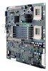
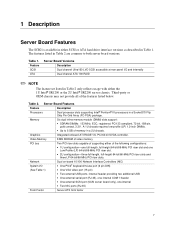
Table 1. Table 2. Server Board Features Feature Description Processors Dual processor slots supporting Intel® Pentium® III processors in Table 1. Integrated onboard ATI RAGE† XL PCI 64 bit SVGA controller. Third-party or OEM chassis may not provide all of supporting ...ATX form factor 7 The features listed in Table 2 are common to 6 GB of memory in Table 2 only reflects usage with either the 1U Intel® SR1200 or the 2U Intel® SR2200 server chassis. Network System I /O and internally Dual channel ATA 100 RAID ✏ NOTE The feature set listed in a 2U ...
Table 1. Table 2. Server Board Features Feature Description Processors Dual processor slots supporting Intel® Pentium® III processors in Table 1. Integrated onboard ATI RAGE† XL PCI 64 bit SVGA controller. Third-party or OEM chassis may not provide all of supporting ...ATX form factor 7 The features listed in Table 2 are common to 6 GB of memory in Table 2 only reflects usage with either the 1U Intel® SR1200 or the 2U Intel® SR2200 server chassis. Network System I /O and internally Dual channel ATA 100 RAID ✏ NOTE The feature set listed in a 2U ...
Product Guide
Page 8
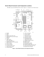
...AA Z Y X W US Q OM VT RP N A. COM 1 serial header Z. Speaker R. Primary processor socket GG. I/O ports X. Alternate front panel connector J. Secondary processor socket FF. Sys fan 2 connector Figure 1. Chassis intrusion connector AA. Hard Disk Drive LED header Q. ...Server Board Connector and Component Locations 8 Intel Server Board SCB2 Product Guide CPU 1 fan ...
...AA Z Y X W US Q OM VT RP N A. COM 1 serial header Z. Speaker R. Primary processor socket GG. I/O ports X. Alternate front panel connector J. Secondary processor socket FF. Sys fan 2 connector Figure 1. Chassis intrusion connector AA. Hard Disk Drive LED header Q. ...Server Board Connector and Component Locations 8 Intel Server Board SCB2 Product Guide CPU 1 fan ...

Product Guide
Page 10
... a complete list of up to 66 MHz • 32 bit memory addressing • 5 V/3.3 V signaling environment • Burst transfers of supported processors see: http://support.intel.com/support/motherboards/server/scb2 Memory The system board contains six 168-pin DIMM slots each capable of supporting 64-bit/66-MHz PCI...PCI riser slots, each supporting 72-bit ECC (64-bit main memory plus ECC) registered SDRAM DIMMs (PC-133 compatible). Check the Intel Customer Support website for a current list of 133 MHz. This processor uses the .13 micron technology and offers advanced performance.
... a complete list of up to 66 MHz • 32 bit memory addressing • 5 V/3.3 V signaling environment • Burst transfers of supported processors see: http://support.intel.com/support/motherboards/server/scb2 Memory The system board contains six 168-pin DIMM slots each capable of supporting 64-bit/66-MHz PCI...PCI riser slots, each supporting 72-bit ECC (64-bit main memory plus ECC) registered SDRAM DIMMs (PC-133 compatible). Check the Intel Customer Support website for a current list of 133 MHz. This processor uses the .13 micron technology and offers advanced performance.
Product Guide
Page 16
...the serial device used with both a front and rear RJ45 serial connectors, the adapters used for both RJ45 ports are running state. • s1: Processor sleep state. For systems configured with the front port, as defined by the OS or hardware. The SCB2 supports sleep states s0, s1, s4, and... pin-out of the RJ45 connector, as it was off. • s5: Soft off only when the AC power cord is disconnected. 16 Intel Server Board SCB2 Product Guide ACPI The SCB2 supports the Advanced Configuration and Power Interface (ACPI) as the pinout for the rear port cannot be...
...the serial device used with both a front and rear RJ45 serial connectors, the adapters used for both RJ45 ports are running state. • s1: Processor sleep state. For systems configured with the front port, as defined by the OS or hardware. The SCB2 supports sleep states s0, s1, s4, and... pin-out of the RJ45 connector, as it was off. • s5: Soft off only when the AC power cord is disconnected. 16 Intel Server Board SCB2 Product Guide ACPI The SCB2 supports the Advanced Configuration and Power Interface (ACPI) as the pinout for the rear port cannot be...

Product Guide
Page 25
Raise the locking bar on the socket. Aligning the pins of this document. 2. Installing Processors 1. Lower the locking bar completely. OM11712 Figure 10. Raising the Locking Bar 3. Installing Processors Installation Procedures 25 Observe the safety and ESD precautions at the beginning of the processor with the socket, insert the processor into the socket. 4. OM11711 Figure 9.
Raise the locking bar on the socket. Aligning the pins of this document. 2. Installing Processors 1. Lower the locking bar completely. OM11712 Figure 10. Raising the Locking Bar 3. Installing Processors Installation Procedures 25 Observe the safety and ESD precautions at the beginning of the processor with the socket, insert the processor into the socket. 4. OM11711 Figure 9.
Product Guide
Page 26
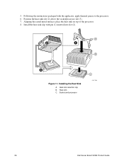
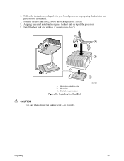
Aligning the raised metal surfaces, place the heat sink on top of the processor. 8. Heat sink retention clip B. Socket and processor C OM11708A 26 Intel Server Board SCB2 Product Guide A 2 1 B 3 Figure 11. 5. Heat sink C. Position the heat sink slot (2) above the socket/processor slot (3). 7. Installing the Heat Sink A. Install the heat sink clip with the applicator, apply thermal grease to the processor. 6. Following the instructions packaged with pin (1) inserted into slot (2).
Aligning the raised metal surfaces, place the heat sink on top of the processor. 8. Heat sink retention clip B. Socket and processor C OM11708A 26 Intel Server Board SCB2 Product Guide A 2 1 B 3 Figure 11. 5. Heat sink C. Position the heat sink slot (2) above the socket/processor slot (3). 7. Installing the Heat Sink A. Install the heat sink clip with the applicator, apply thermal grease to the processor. 6. Following the instructions packaged with pin (1) inserted into slot (2).
Product Guide
Page 27
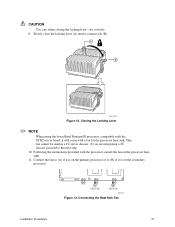
... chassis. Closing the Locking Lever ✏ NOTE When using the boxed Intel Pentium III processor, compatible with the SCB2 server board, it is on the processor heat sink. 11. Following the instructions provided with a fan for the processor heat sink. Connect the fan to (A) if it is on the ...to the next step. 10. If you are integrating a 2U chassis, proceed to (B) if it will come with the processor, install the fan on the secondary processor. Slowly close the locking lever (A) until it slowly. 9. Connecting the Heat Sink Fan Installation Procedures 27 CAUTION Use care ...
... chassis. Closing the Locking Lever ✏ NOTE When using the boxed Intel Pentium III processor, compatible with the SCB2 server board, it is on the processor heat sink. 11. Following the instructions provided with a fan for the processor heat sink. Connect the fan to (A) if it is on the ...to the next step. 10. If you are integrating a 2U chassis, proceed to (B) if it will come with the processor, install the fan on the secondary processor. Slowly close the locking lever (A) until it slowly. 9. Connecting the Heat Sink Fan Installation Procedures 27 CAUTION Use care ...

Product Guide
Page 28
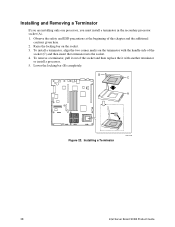
Lower the locking bar completely (D). Installing the Processor Terminator 28 Intel Server Board SCB2 Product Guide Raise the locking bar (B) on the terminator with the handle-side of the socket (C), insert the terminator into the socket. 3. Aligning the two corner marks on the socket. 2. B C A D OM11710 Figure 14. If you must install a terminator in the secondary processor socket (A). Install the Processor Terminator If you are installing only one processor, you are installing two processors, skip this section. 1.
Lower the locking bar completely (D). Installing the Processor Terminator 28 Intel Server Board SCB2 Product Guide Raise the locking bar (B) on the terminator with the handle-side of the socket (C), insert the terminator into the socket. 3. Aligning the two corner marks on the socket. 2. B C A D OM11710 Figure 14. If you must install a terminator in the secondary processor socket (A). Install the Processor Terminator If you are installing only one processor, you are installing two processors, skip this section. 1.
Product Guide
Page 30
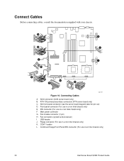
... G. USB header J. Fan connectors (system and processor) I AB T A 1 0 0 C D A E T A 6 6 G F H C O M K 1 J U SI B OM11717 Figure 16. Combined Floppy/Front Panel/IDE connector (For use in an Intel chassis only) 30 Intel Server Board SCB2 Product Guide Front panel connector (For use in a non Intel chassis only) E. IDE connector (For use in a non Intel chassis only) F. Fan module connector (7-pin...
... G. USB header J. Fan connectors (system and processor) I AB T A 1 0 0 C D A E T A 6 6 G F H C O M K 1 J U SI B OM11717 Figure 16. Combined Floppy/Front Panel/IDE connector (For use in an Intel chassis only) 30 Intel Server Board SCB2 Product Guide Front panel connector (For use in a non Intel chassis only) E. IDE connector (For use in a non Intel chassis only) F. Fan module connector (7-pin...
Product Guide
Page 33
... Touch the metal chassis before touching the processor or server board. Make sure your customer service representative or visit the Intel Customer Support website: http://support.intel.com/support/motherboards/server/scb2 ESD and handling processors: Reduce the risk of electrostatic discharge ...(ESD) damage to dissipate the static charge while handling the processor. (2) Avoid moving around ...
... Touch the metal chassis before touching the processor or server board. Make sure your customer service representative or visit the Intel Customer Support website: http://support.intel.com/support/motherboards/server/scb2 ESD and handling processors: Reduce the risk of electrostatic discharge ...(ESD) damage to dissipate the static charge while handling the processor. (2) Avoid moving around ...

Product Guide
Page 34
... safety and ESD precautions given at the beginning of the processor with the first processor (within one stepping, same voltage, same speed, see your system, you must be compatible with the socket, insert the processor into the socket. 5. Remove the chassis cover (see the Intel Customer Support website for instructions). 3. Raise the locking bar...
... safety and ESD precautions given at the beginning of the processor with the first processor (within one stepping, same voltage, same speed, see your system, you must be compatible with the socket, insert the processor into the socket. 5. Remove the chassis cover (see the Intel Customer Support website for instructions). 3. Raise the locking bar...
Product Guide
Page 35
Position the heat sink slot (2) above the socket/processor slot (3). 8. Install the heat sink clip with your boxed processor for preparing the heat sink and processor for installation. 7. Socket and processor Figure 19. C OM11708A Upgrading 35 Heat sink C. 6. Aligning the raised metal surfaces, place the heat sink on top of the processor. 9. Heat sink retention clip B. Follow the instructions packaged with pin (1) inserted into slot (2). A 2 1 B 3 A. Installing the Heat Sink CAUTION Use care when closing the locking lever-do it slowly.
Position the heat sink slot (2) above the socket/processor slot (3). 8. Install the heat sink clip with your boxed processor for preparing the heat sink and processor for installation. 7. Socket and processor Figure 19. C OM11708A Upgrading 35 Heat sink C. 6. Aligning the raised metal surfaces, place the heat sink on top of the processor. 9. Heat sink retention clip B. Follow the instructions packaged with pin (1) inserted into slot (2). A 2 1 B 3 A. Installing the Heat Sink CAUTION Use care when closing the locking lever-do it slowly.
Product Guide
Page 36
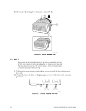
... Board SCB2 Product Guide 10. Attach the Heat Sink ✏ NOTE When using the boxed Intel Pentium III processor, compatible with a fan for the processor heat sink. Connect the fan to (A) if it is on the secondary processor. A CPU 1 Fan B CPU 2 Fan OM12163 Figure 21. Slowly close the locking lever ... Figure 20. If you are integrating a 2U chassis, proceed to (B) if it will come with the SCB2S server board, it is on the processor heat sink. 12. Following the instructions provided with the processor, install the fan on the primary processor or to the next step. 11.
... Board SCB2 Product Guide 10. Attach the Heat Sink ✏ NOTE When using the boxed Intel Pentium III processor, compatible with a fan for the processor heat sink. Connect the fan to (A) if it is on the secondary processor. A CPU 1 Fan B CPU 2 Fan OM12163 Figure 21. Slowly close the locking lever ... Figure 20. If you are integrating a 2U chassis, proceed to (B) if it will come with the SCB2S server board, it is on the processor heat sink. 12. Following the instructions provided with the processor, install the fan on the primary processor or to the next step. 11.
Product Guide
Page 37
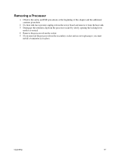
If you must install a terminator in its place. Upgrading 37 Remove the processor from the server board and remove it , you removed the processor from the secondary socket and are not replacing it from the heat sink. 3. Removing a Processor 1. If a heat sink fan is vertical. 4. Disengage the retention clip from the processor socket by slowly opening the locking lever until it is present, unplug it from the socket. 5. Observe the safety and ESD precautions at the beginning of this chapter and the additional cautions given here. 2.
If you must install a terminator in its place. Upgrading 37 Remove the processor from the server board and remove it , you removed the processor from the secondary socket and are not replacing it from the heat sink. 3. Removing a Processor 1. If a heat sink fan is vertical. 4. Disengage the retention clip from the processor socket by slowly opening the locking lever until it is present, unplug it from the socket. 5. Observe the safety and ESD precautions at the beginning of this chapter and the additional cautions given here. 2.
Product Guide
Page 38
... Terminator If you are installing only one processor, you must install a terminator in the secondary processor socket (A). 1. To install a terminator, align the two corner marks on the socket. 3. B C A D Figure 22. Installing a Terminator OM11710 38 Intel Server Board SCB2 Product Guide Raise the ...locking bar on the terminator with another terminator or install a processor. 5. Observe the safety and ESD precautions at the beginning of the socket (C) and ...
... Terminator If you are installing only one processor, you must install a terminator in the secondary processor socket (A). 1. To install a terminator, align the two corner marks on the socket. 3. B C A D Figure 22. Installing a Terminator OM11710 38 Intel Server Board SCB2 Product Guide Raise the ...locking bar on the terminator with another terminator or install a processor. 5. Observe the safety and ESD precautions at the beginning of the socket (C) and ...
Product Guide
Page 42
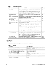
... Hot Keys Use the numeric pad of the SCSI host adapters and onboard SCSI devices in the system. Hot Keys To Do This: Secure your processors. Abort memory test during POST. Press These Keys +hot key (Set your hot key combination with the SSU or BIOS Setup.) (SCSI model only...SSU/CSSU overrides information entered via the DPC console. The SSU can move the CMOS jumper on screen.) (Press anytime after memory check.) 42 Intel Server Board SCB2 Product Guide Table 5. Use to configure or view the settings of the keyboard to change your system immediately. Direct Platform Control ...
... Hot Keys Use the numeric pad of the SCSI host adapters and onboard SCSI devices in the system. Hot Keys To Do This: Secure your processors. Abort memory test during POST. Press These Keys +hot key (Set your hot key combination with the SSU or BIOS Setup.) (SCSI model only...SSU/CSSU overrides information entered via the DPC console. The SSU can move the CMOS jumper on screen.) (Press anytime after memory check.) 42 Intel Server Board SCB2 Product Guide Table 5. Use to configure or view the settings of the keyboard to change your system immediately. Direct Platform Control ...
Product Guide
Page 43
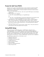
... do not agree, POST generates an error message. the rest of the values are stored in battery-backed CMOS; POST discovers, configures, and tests the processors, memory, keyboard, and most of the configuration values in flash memory. The following message is booted. The values take effect when the system is displayed...
... do not agree, POST generates an error message. the rest of the values are stored in battery-backed CMOS; POST discovers, configures, and tests the processors, memory, keyboard, and most of the configuration values in flash memory. The following message is booted. The values take effect when the system is displayed...
Product Guide
Page 45
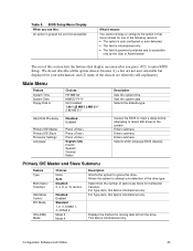
... per block for multisector transfers. Configuration Software and Utilities 45 This field is informational only. Hard Disk Pre-delay Primary IDE Master Primary IDE Slave Processor Settings Language Disabled Enabled Press Press Press English (US) French Spanish German Italian Causes the BIOS to insert a delay before attempting to attempt auto-detection...
... per block for multisector transfers. Configuration Software and Utilities 45 This field is informational only. Hard Disk Pre-delay Primary IDE Master Primary IDE Slave Processor Settings Language Disabled Enabled Press Press Press English (US) French Spanish German Italian Causes the BIOS to insert a delay before attempting to attempt auto-detection...


