User Guide
Page 3
...; Processor(s), DDR2-400 system memory DIMMs, hard drive(s), floppy drive, CD-ROM or DVD-ROM drive, RAID controller, operating system Intel® Server Board SE7520AF2 User Guide iii Preface Preface About this Manual Thank you for purchasing and using the utilities that are responsible for troubleshooting, upgrading, and repairing this chapter, you will find BIOS error messages and POST code messages. This document provides a brief overview of the features of the board/chassis, a list of a problem. In this server board. Chapter 4 provides troubleshooting...
...; Processor(s), DDR2-400 system memory DIMMs, hard drive(s), floppy drive, CD-ROM or DVD-ROM drive, RAID controller, operating system Intel® Server Board SE7520AF2 User Guide iii Preface Preface About this Manual Thank you for purchasing and using the utilities that are responsible for troubleshooting, upgrading, and repairing this chapter, you will find BIOS error messages and POST code messages. This document provides a brief overview of the features of the board/chassis, a list of a problem. In this server board. Chapter 4 provides troubleshooting...
User Guide
Page 7
...use ein. Wichtige Sicherheitshinweise Lesen Sie zunächst sämtliche Warn- Auf der Rückseite des Systems beschriften und ziehen Sie alle Anschlußkabel von den I /O connectors or ports on the Resource CD and/or at http://support.intel.com/support/motherboards...when handling components. 6. Turn off all peripheral devices connected to access the inside of the system-any of the system. 5. Intel® Server Board SE7520AF2 User Guide vii SAFETY STEPS: Whenever you remove the chassis covers to the system. 2. Label and disconnect all AC power cords from the system...
...use ein. Wichtige Sicherheitshinweise Lesen Sie zunächst sämtliche Warn- Auf der Rückseite des Systems beschriften und ziehen Sie alle Anschlußkabel von den I /O connectors or ports on the Resource CD and/or at http://support.intel.com/support/motherboards...when handling components. 6. Turn off all peripheral devices connected to access the inside of the system-any of the system. 5. Intel® Server Board SE7520AF2 User Guide vii SAFETY STEPS: Whenever you remove the chassis covers to the system. 2. Label and disconnect all AC power cords from the system...
User Guide
Page 10
...1 Server Board Features 1 Connector and Header Locations 4 Configuration Jumpers...5 Back Panel Connectors ...6 Hardware Requirements...7 2 Hardware Installations and Upgrades 11 Before You Begin ...11 Tools and Supplies Needed 11 Installing and Removing Memory 11 Installing DIMMs ...12 Removing DIMMs ...13 Installing or Replacing the Processor 13 Installing the Processor 14 Removing a Processor 16 Installing or Removing a PCI Card 17 Replacing the Backup Battery 20 3 Server Utilities 23 Using the BIOS Setup Utility 23 Starting Setup...23 If You Cannot Access Setup 23 Setup Menus...
...1 Server Board Features 1 Connector and Header Locations 4 Configuration Jumpers...5 Back Panel Connectors ...6 Hardware Requirements...7 2 Hardware Installations and Upgrades 11 Before You Begin ...11 Tools and Supplies Needed 11 Installing and Removing Memory 11 Installing DIMMs ...12 Removing DIMMs ...13 Installing or Replacing the Processor 13 Installing the Processor 14 Removing a Processor 16 Installing or Removing a PCI Card 17 Replacing the Backup Battery 20 3 Server Utilities 23 Using the BIOS Setup Utility 23 Starting Setup...23 If You Cannot Access Setup 23 Setup Menus...
User Guide
Page 12
... Table 7. Boot Block Error Beep Codes 43 Table 8. Six DIMM Memory Mirroring 8 Figure 7. Inserting Processor 14 Figure 11. POST Error Beep Codes 44 Table 9. Configuration Jumper [J1D1 5 Table 3. Opening Socket Lever 14 Figure 10. Removing the PCI Air Duct 17 Figure 14. Installing Heat Sink 16 Figure 13. Resetting the System 34 Table 6. Back Panel Connectors 6 Figure 5. Replacing the Backup Battery 21 Figure 17. Troubleshooting BIOS Beep Codes 44 Intel® Server Board SE7520AF2 User Guide xiii Intel® Server Board SE7520AF2 1 Figure...
... Table 7. Boot Block Error Beep Codes 43 Table 8. Six DIMM Memory Mirroring 8 Figure 7. Inserting Processor 14 Figure 11. POST Error Beep Codes 44 Table 9. Configuration Jumper [J1D1 5 Table 3. Opening Socket Lever 14 Figure 10. Removing the PCI Air Duct 17 Figure 14. Installing Heat Sink 16 Figure 13. Resetting the System 34 Table 6. Back Panel Connectors 6 Figure 5. Replacing the Backup Battery 21 Figure 17. Troubleshooting BIOS Beep Codes 44 Intel® Server Board SE7520AF2 User Guide xiii Intel® Server Board SE7520AF2 1 Figure...
User Guide
Page 14
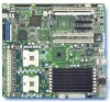
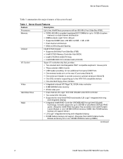
... DDR333 memory DIMM.) Continued 2 Intel® Server Board SE7520AF2 User Guide Table 1. Includes support for up to two ATA-100 compatible devices ƒ One standard floppy drive interface ƒ Integrated onboard ATI Rage* XL SVGA video controller ƒ 8 MB SDRAM video memory ƒ SVGA video port ƒ Dual-channel LSI Logic* 53C1030 Ultra320 wide SCSI controller ƒ Two serial ATA 150 ports ƒ Supported for two additional front panel USB Ports ƒ One external serial port on the rear I /O controller chip...
... DDR333 memory DIMM.) Continued 2 Intel® Server Board SE7520AF2 User Guide Table 1. Includes support for up to two ATA-100 compatible devices ƒ One standard floppy drive interface ƒ Integrated onboard ATI Rage* XL SVGA video controller ƒ 8 MB SDRAM video memory ƒ SVGA video port ƒ Dual-channel LSI Logic* 53C1030 Ultra320 wide SCSI controller ƒ Two serial ATA 150 ports ƒ Supported for two additional front panel USB Ports ƒ One external serial port on the rear I /O controller chip...
User Guide
Page 15
... (Hot-Plug capable on Hot Plug SKU only.) ƒ Slot 6: PCI-X* 64-bit/100 MHz (One slot and two slot riser capable.) ƒ Six multi-speed system fan headers ƒ Two single-speed CPU fan headers ƒ National Semiconductor* PC87431 controller to provide monitoring, alerting and logging of critical sensor information ƒ Intel® Light Guided Diagnostics on critical FRU devices, such as processors, memory, and power ƒ Front panel LCD connectors for the RAID DIMM.
... (Hot-Plug capable on Hot Plug SKU only.) ƒ Slot 6: PCI-X* 64-bit/100 MHz (One slot and two slot riser capable.) ƒ Six multi-speed system fan headers ƒ Two single-speed CPU fan headers ƒ National Semiconductor* PC87431 controller to provide monitoring, alerting and logging of critical sensor information ƒ Intel® Light Guided Diagnostics on critical FRU devices, such as processors, memory, and power ƒ Front panel LCD connectors for the RAID DIMM.
User Guide
Page 17
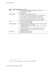
...the BIOS by loading the BIOS code into the flash device from a bootable recovery device. Password Clear 5-6 Protect: These pins should be jumpered for normal operation. 10-11 Recovery Boot: If these pins are jumpered, the CMOS settings will be jumpered for normal operation. 6-7 Erase: If these pins are jumpered, the system will be jumpered for normal operation. Recovery Boot 9-10 Normal Boot: These pins should be cleared on the next reset. Intel® Server Board SE7520AF2 User Guide 5 Configuration Jumper Location Table 2. Server Board Features Configuration Jumpers...
...the BIOS by loading the BIOS code into the flash device from a bootable recovery device. Password Clear 5-6 Protect: These pins should be jumpered for normal operation. 10-11 Recovery Boot: If these pins are jumpered, the CMOS settings will be jumpered for normal operation. 6-7 Erase: If these pins are jumpered, the system will be jumpered for normal operation. Recovery Boot 9-10 Normal Boot: These pins should be cleared on the next reset. Intel® Server Board SE7520AF2 User Guide 5 Configuration Jumper Location Table 2. Server Board Features Configuration Jumpers...
User Guide
Page 19
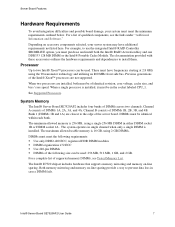
... two channels. When a single processor is 256 MB, using the 90 nanometer technology and utilizing an 800 MHz front side bus. See Supported Processors. Depending on accessory components selected, your system must meet the minimum requirements outlined below. Bank 1 (DIMMs 1B and 1A) are not supported. Intel® Server Board SE7520AF2 User Guide 7 For a list of supported memory DIMMs, see the links under "Additional Information and Software." Channel B consists...
... two channels. When a single processor is 256 MB, using the 90 nanometer technology and utilizing an 800 MHz front side bus. See Supported Processors. Depending on accessory components selected, your system must meet the minimum requirements outlined below. Bank 1 (DIMMs 1B and 1A) are not supported. Intel® Server Board SE7520AF2 User Guide 7 For a list of supported memory DIMMs, see the links under "Additional Information and Software." Channel B consists...

User Guide
Page 28
... be equipped with a standard full-height PCI mounting bracket. If a low profile card is reserved for the RAID DIMM accessory. If you have the hot-plug version of the PCI hot-plug features only if you have the hot-plug kit installed you can hot swap PCI cards in PCI slots 1, 3, 4, and 5. Removing the PCI Air Duct Intel® Server Board SE7520AF2 User Guide 17 Do not attempt to add...
... be equipped with a standard full-height PCI mounting bracket. If a low profile card is reserved for the RAID DIMM accessory. If you have the hot-plug version of the PCI hot-plug features only if you have the hot-plug kit installed you can hot swap PCI cards in PCI slots 1, 3, 4, and 5. Removing the PCI Air Duct Intel® Server Board SE7520AF2 User Guide 17 Do not attempt to add...

User Guide
Page 36
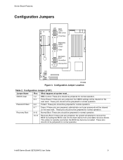
... BIOS upgrade. The password clear jumper is completed. Power down the system and boot it again. The system will reset automatically when the BIOS update process is located on jumper block J1D1. 1. If this happens, shut down the system and disconnect the AC power. 2. Password Clear Jumper 26 Intel® Server Board SE7520AF2 User Guide Upgrading the BIOS Upgrading the BIOS Follow the instructions in the following diagram. The Password Clear jumper must be set. J1D1 1 2 3 CMOS CLEAR BMC Control Force Erase PASSWORD 5 CLEAR Protect 6 Erase 7 RECOVERY 9 BOOT...
... BIOS upgrade. The password clear jumper is completed. Power down the system and boot it again. The system will reset automatically when the BIOS update process is located on jumper block J1D1. 1. If this happens, shut down the system and disconnect the AC power. 2. Password Clear Jumper 26 Intel® Server Board SE7520AF2 User Guide Upgrading the BIOS Upgrading the BIOS Follow the instructions in the following diagram. The Password Clear jumper must be set. J1D1 1 2 3 CMOS CLEAR BMC Control Force Erase PASSWORD 5 CLEAR Protect 6 Erase 7 RECOVERY 9 BOOT...

User Guide
Page 38
... clears system memory, restarts POST, reloads the operating system, and halts power to reset your system, such as video drivers, network drivers, and SCSI drivers. Press: Reset button Power off and then on the server board? ‰ Are all jumper settings on Problems following Initial System Installation Problems that occur at the wall outlet? ‰ Are the power supplies plugged in -depth troubleshooting, attempt to all add-in PCI boards fully seated in your system using...
... clears system memory, restarts POST, reloads the operating system, and halts power to reset your system, such as video drivers, network drivers, and SCSI drivers. Press: Reset button Power off and then on the server board? ‰ Are all jumper settings on Problems following Initial System Installation Problems that occur at the wall outlet? ‰ Are the power supplies plugged in -depth troubleshooting, attempt to all add-in PCI boards fully seated in your system using...

User Guide
Page 39
... "Power Light Does Not Light." 28 Intel® Server Board SE7520AF2 User Guide To check these settings, refer to the manufacturer's documentation that there are correctly connected to boot from a floppy diskette or from the system, turn the server on (power on add-in the CD-ROM drive. 5. If applicable, ensure that came with your video display monitor and keyboard are no CD-ROM disk in boards and peripheral devices correct? Turn off devices before disconnecting cables...
... "Power Light Does Not Light." 28 Intel® Server Board SE7520AF2 User Guide To check these settings, refer to the manufacturer's documentation that there are correctly connected to boot from a floppy diskette or from the system, turn the server on (power on add-in the CD-ROM drive. 5. If applicable, ensure that came with your video display monitor and keyboard are no CD-ROM disk in boards and peripheral devices correct? Turn off devices before disconnecting cables...

User Guide
Page 41
... board and cause a short. Verify that the video controller board is functioning. ‰ Is the video monitor plugged in and turned on Screen Check the following : 1. Troubleshooting ‰ Remove all add-in cards and see if the system boots. If there are using the onboard video controller. 2. If you do not receive a beep code and characters do the following : ‰ Is the keyboard functioning? Verify that the video works using a switch box, is it by turning...
... board and cause a short. Verify that the video controller board is functioning. ‰ Is the video monitor plugged in and turned on Screen Check the following : 1. Troubleshooting ‰ Remove all add-in cards and see if the system boots. If there are using the onboard video controller. 2. If you do not receive a beep code and characters do the following : ‰ Is the keyboard functioning? Verify that the video works using a switch box, is it by turning...

User Guide
Page 42
... all relevant switches and jumpers on the diskette drive set correctly? ‰ Is the diskette drive properly configured? ‰ Is the diskette drive activity light always on the video monitor? If you are using the onboard diskette controller, use the BIOS setup to make sure that "Onboard Floppy" is set to "Disabled." 31 See the manufacturer's documentation. ‰ Are the video monitor's signal and power cables properly installed? ‰ Does this video monitor work correctly if plugged into power connector sockets the...
... all relevant switches and jumpers on the diskette drive set correctly? ‰ Is the diskette drive properly configured? ‰ Is the diskette drive activity light always on the video monitor? If you are using the onboard diskette controller, use the BIOS setup to make sure that "Onboard Floppy" is set to "Disabled." 31 See the manufacturer's documentation. ‰ Are the video monitor's signal and power cables properly installed? ‰ Does this video monitor work correctly if plugged into power connector sockets the...

User Guide
Page 43
... the drivers. 32 Intel® Server Board SE7520AF2 User Guide Troubleshooting CD-ROM Drive or DVD-ROM Drive Activity Light Does Not Light Check the following: ‰ Are the CD-ROM/DVD-ROM drive's power and signal cables properly installed? ‰ Are all relevant switches and jumpers on changing interrupts.. then try a different slot if necessary. ‰ The network driver files may require interrupts that came with other adapter supports shared interrupts. See the documentation that are directly connecting two...
... the drivers. 32 Intel® Server Board SE7520AF2 User Guide Troubleshooting CD-ROM Drive or DVD-ROM Drive Activity Light Does Not Light Check the following: ‰ Are the CD-ROM/DVD-ROM drive's power and signal cables properly installed? ‰ Are all relevant switches and jumpers on changing interrupts.. then try a different slot if necessary. ‰ The network driver files may require interrupts that came with other adapter supports shared interrupts. See the documentation that are directly connecting two...

User Guide
Page 44
... some parts of the system have occurred, reload the software and try running correctly sometimes indicate equipment failure. Problems with the power button on the front of voltage spikes include a flickering video display, unexpected system reboots, and the system not responding to the software, not the server hardware. However, they can also be caused by using the power button on the front panel. Before installing a PCI card...
... some parts of the system have occurred, reload the software and try running correctly sometimes indicate equipment failure. Problems with the power button on the front of voltage spikes include a flickering video display, unexpected system reboots, and the system not responding to the software, not the server hardware. However, they can also be caused by using the power button on the front panel. Before installing a PCI card...

User Guide
Page 45
... Information and Software" for details on setting the master/slave settings. ‰ If using a RAID configuration with SCSI or SATA drives, make sure the RAID card is compatible. Devices are not Recognized under Device Manager (Windows* Operating System) The Windows* operating systems do not include all of the above symptoms that is plugged into the power supply. ‰ Make sure the drive is installed correctly. Bootable CD-ROM Is Not Detected...
... Information and Software" for details on setting the master/slave settings. ‰ If using a RAID configuration with SCSI or SATA drives, make sure the RAID card is compatible. Devices are not Recognized under Device Manager (Windows* Operating System) The Windows* operating systems do not include all of the above symptoms that is plugged into the power supply. ‰ Make sure the drive is installed correctly. Bootable CD-ROM Is Not Detected...

User Guide
Page 46
... or Amber IDE activity Front panel DIMM fault Identify failing memory module POST code 1-4 (LSB, bit1, bit2, MSB) Fan Pack Fault CPU 1 & 2 Fan Fault CPU 1 & 2 Fault 5v Standby Power LED Display boot 80 POST code Warn on fan failure Identify fan failure Identify processor failure Identify 5v standby power on state Identify the power state of the system Front panel and board left side Inside the system, at the front of each DIMM socket Left rear...
... or Amber IDE activity Front panel DIMM fault Identify failing memory module POST code 1-4 (LSB, bit1, bit2, MSB) Fan Pack Fault CPU 1 & 2 Fan Fault CPU 1 & 2 Fault 5v Standby Power LED Display boot 80 POST code Warn on fan failure Identify fan failure Identify processor failure Identify 5v standby power on state Identify the power state of the system Front panel and board left side Inside the system, at the front of each DIMM socket Left rear...

User Guide
Page 47
... in drive A: 3 Base Memory error 4 Flash Programming successful 5 Floppy read error 6 Keyboard controller BAT command failed 7 No Flash EPROM detected 8 Floppy controller failure 9 Boot Block BIOS checksum error 10 Flash Erase error 11 Flash Program error 12 'AMIBOOT.ROM' file size error 13 BIOS ROM image mismatch (file layout does not match image present in flash device) 1 long beep Insert diskette with AMIBOOT.001 File for Multi-Disk Recovery 36 Intel® Server Board SE7520AF2 User Guide Prior to system video initialization, the BIOS uses these beep codes to...
... in drive A: 3 Base Memory error 4 Flash Programming successful 5 Floppy read error 6 Keyboard controller BAT command failed 7 No Flash EPROM detected 8 Floppy controller failure 9 Boot Block BIOS checksum error 10 Flash Erase error 11 Flash Program error 12 'AMIBOOT.ROM' file size error 13 BIOS ROM image mismatch (file layout does not match image present in flash device) 1 long beep Insert diskette with AMIBOOT.001 File for Multi-Disk Recovery 36 Intel® Server Board SE7520AF2 User Guide Prior to system video initialization, the BIOS uses these beep codes to...

User Guide
Page 48
... 5 Processor error 6 8042 Gate A20 test error (cannot switch to inform users on error conditions. POST Error Beep Codes Number of the system board, the board may be displayed, speaker beeps are necessary to the Intel® Server Board SE7520AF2 Technical Product Specification. 37 Troubleshooting BIOS Beep Codes Number of Beeps Troubleshooting Action 1, 2 or 3 Reseat the memory, or replace with known good modules. 4-7, 9-11 Fatal error indicating a serious problem with a Bootblock update refer to inform the user of a Bootblock update, where video is...
... 5 Processor error 6 8042 Gate A20 test error (cannot switch to inform users on error conditions. POST Error Beep Codes Number of the system board, the board may be displayed, speaker beeps are necessary to the Intel® Server Board SE7520AF2 Technical Product Specification. 37 Troubleshooting BIOS Beep Codes Number of Beeps Troubleshooting Action 1, 2 or 3 Reseat the memory, or replace with known good modules. 4-7, 9-11 Fatal error indicating a serious problem with a Bootblock update refer to inform the user of a Bootblock update, where video is...


