
User Guide
Page 1
Intel® Server System SR1550AL/ SR1550ALSAS User's Guide A Guide for Technically Qualified Assemblers of Intel® Identified Subassemblies/ Products Intel Order Number D31972-002
Intel® Server System SR1550AL/ SR1550ALSAS User's Guide A Guide for Technically Qualified Assemblers of Intel® Identified Subassemblies/ Products Intel Order Number D31972-002
User Guide
Page 2
... a number of high-density VLSI and power delivery components that chooses not to fitness for cooling. Disclaimer Information in this document. All Rights Reserved ii Intel® Server System SR1550AL/SR1550ALSAS User's Guide Intel products are designed and tested to determine the amount of any express or implied warranty, relating to sale and/or use...
... a number of high-density VLSI and power delivery components that chooses not to fitness for cooling. Disclaimer Information in this document. All Rights Reserved ii Intel® Server System SR1550AL/SR1550ALSAS User's Guide Intel products are designed and tested to determine the amount of any express or implied warranty, relating to sale and/or use...

User Guide
Page 6
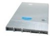
... hardware box • Rack handles, in the hardware box • USB cable • Peripheral bay filler panel, installed in the server system • Mini control panel, installed in the server system • Active or passive mid-plane, installed in the server system vi Intel® Server System SR1550AL/SR1550ALSAS User's Guide Intel® Server System SR1550AL Contents Your Intel® Server System SR1550AL ships with the Intel® Server Board S5000PAL.
... hardware box • Rack handles, in the hardware box • USB cable • Peripheral bay filler panel, installed in the server system • Mini control panel, installed in the server system • Active or passive mid-plane, installed in the server system vi Intel® Server System SR1550AL/SR1550ALSAS User's Guide Intel® Server System SR1550AL Contents Your Intel® Server System SR1550AL ships with the Intel® Server Board S5000PAL.
User Guide
Page 8
http://support.intel.com/support/motherboards/server/sb/CS-010770.htm 上的 Intel Server Boards and Server Chassis Safety Information(《Intel viii Intel® Server System SR1550AL/SR1550ALSAS User's Guide
http://support.intel.com/support/motherboards/server/sb/CS-010770.htm 上的 Intel Server Boards and Server Chassis Safety Information(《Intel viii Intel® Server System SR1550AL/SR1550ALSAS User's Guide

User Guide
Page 9
... on a grounded, static free surface. Take care to grip with product regulations in the region(s) in this guide. Intel® Server System SR1550AL/SR1550ALSAS User's Guide ix You must unplug the AC power cord from the server, place the board component side up on top that you perform all procedures in this guide or any components...
... on a grounded, static free surface. Take care to grip with product regulations in the region(s) in this guide. Intel® Server System SR1550AL/SR1550ALSAS User's Guide ix You must unplug the AC power cord from the server, place the board component side up on top that you perform all procedures in this guide or any components...

User Guide
Page 11
... 27 Figure 20. Installing the Memory 30 Figure 25. Intel® Integrated Server System SR1550AL 3 Figure 2. Active SAS/SATA Mid-Plane Components 14 Figure 10. Front Bezel Supporting the Standard Control Panel 24 Figure 15. Installing the Interposer Board to the Server Board 48 Intel® Server System SR1550AL/SR1550ALSAS User's Guide xi Removing the Processor 2 Air Dam (Optional - Installing...
... 27 Figure 20. Installing the Memory 30 Figure 25. Intel® Integrated Server System SR1550AL 3 Figure 2. Active SAS/SATA Mid-Plane Components 14 Figure 10. Front Bezel Supporting the Standard Control Panel 24 Figure 15. Installing the Interposer Board to the Server Board 48 Intel® Server System SR1550AL/SR1550ALSAS User's Guide xi Removing the Processor 2 Air Dam (Optional - Installing...

User Guide
Page 12
... 49. Removing Mini Control Panel Module from the Server System 51 Figure 45. Diagnostic LED Placement Diagram 106 xii Intel® Server System SR1550AL/SR1550ALSAS User's Guide Installing the Mid-plane Board into the Server System 54 Figure 47. Removing the Intel® RMM and the Intel® RMM NIC Module from the Server System 68 Figure 60. Removing the Power Distribution Board...
... 49. Removing Mini Control Panel Module from the Server System 51 Figure 45. Diagnostic LED Placement Diagram 106 xii Intel® Server System SR1550AL/SR1550ALSAS User's Guide Installing the Mid-plane Board into the Server System 54 Figure 47. Removing the Intel® RMM and the Intel® RMM NIC Module from the Server System 68 Figure 60. Removing the Power Distribution Board...

User Guide
Page 13
...About this Manual ...v Manual Organization ...v Product Contents ...vi Intel® Server System SR1550AL Contents vi Safety Information ...vii Important Safety Instructions vii Wichtige Sicherheitshinweise vii Consignes de sécurité ...vii Instrucciones de seguridad importantes vii Chapter 1: Server System References 1 Chapter 2: Server System Features 3 Chassis Component Identification 6 Internal Components ...6 Configuration...Servicing 24 Removing and Installing the Front Bezel 24 Removing the Front Bezel 25 Intel® Server System SR1550AL/SR1550ALSAS User's Guide xiii
...About this Manual ...v Manual Organization ...v Product Contents ...vi Intel® Server System SR1550AL Contents vi Safety Information ...vii Important Safety Instructions vii Wichtige Sicherheitshinweise vii Consignes de sécurité ...vii Instrucciones de seguridad importantes vii Chapter 1: Server System References 1 Chapter 2: Server System Features 3 Chassis Component Identification 6 Internal Components ...6 Configuration...Servicing 24 Removing and Installing the Front Bezel 24 Removing the Front Bezel 25 Intel® Server System SR1550AL/SR1550ALSAS User's Guide xiii

User Guide
Page 14
Installing the Front Bezel 26 Removing and Installing the Chassis Cover 26 Removing the Chassis Cover 26 Installing the Server System Cover 27 Removing and Installing the Processor Air Duct 28 Removing the Processor Air Duct 28 Installing the Processor Air ... the Intel® Integrated RAID Activation Key and the RAID Mini DIMM 55 Removing the Intel® Integrated RAID Activation Key and the RAID Mini DIMM ......... 56 Installing and Removing the RAID Battery Backup Unit (BBU 57 Installing the RAID Battery Backup Unit 57 xiv Intel® Server System SR1550AL/SR1550ALSAS User's...
Installing the Front Bezel 26 Removing and Installing the Chassis Cover 26 Removing the Chassis Cover 26 Installing the Server System Cover 27 Removing and Installing the Processor Air Duct 28 Removing the Processor Air Duct 28 Installing the Processor Air ... the Intel® Integrated RAID Activation Key and the RAID Mini DIMM 55 Removing the Intel® Integrated RAID Activation Key and the RAID Mini DIMM ......... 56 Installing and Removing the RAID Battery Backup Unit (BBU 57 Installing the RAID Battery Backup Unit 57 xiv Intel® Server System SR1550AL/SR1550ALSAS User's...

User Guide
Page 15
...and Removing the Rack Handles 76 Installing the Rack Handles 76 Removing the Rack Handles 76 Chapter 4: Server Utilities 79 Using the BIOS Setup Utility 79 Starting Setup ...79 If You Cannot Access Setup 79 ...System Installation 90 First Steps Checklist ...90 Hardware Diagnostic Testing 91 Verifying Proper Operation of Key System Lights 91 Confirming Loading of the Operating System 91 Specific Problems and Corrective Actions 92 Power Light Does Not Light 92 No Characters Appear on Screen 93 Characters Are Distorted or Incorrect 93 Intel® Server System SR1550AL/SR1550ALSAS...
...and Removing the Rack Handles 76 Installing the Rack Handles 76 Removing the Rack Handles 76 Chapter 4: Server Utilities 79 Using the BIOS Setup Utility 79 Starting Setup ...79 If You Cannot Access Setup 79 ...System Installation 90 First Steps Checklist ...90 Hardware Diagnostic Testing 91 Verifying Proper Operation of Key System Lights 91 Confirming Loading of the Operating System 91 Specific Problems and Corrective Actions 92 Power Light Does Not Light 92 No Characters Appear on Screen 93 Characters Are Distorted or Incorrect 93 Intel® Server System SR1550AL/SR1550ALSAS...

User Guide
Page 16
...not Recognized under Device Manager (Microsoft* Windows* Operating System) ...97 Hard Drive(s) are not Recognized 97 Bootable CD-ROM Disk Is Not Detected 97 LED Information ...98 BIOS POST Beep Codes 98 Appendix C: Intel® Server Issue Report Form 101 Appendix D: LED Decoder 105 ... (RoHS) Compliance 122 End-of-Life / Product Recycling 122 Appendix G: Warranty 123 Limited Warranty for Intel® Chassis Subassembly Products 123 Appendix H: Installation/Assembly Safety Instructions 127 English ...127 Deutsch ...129 xvi Intel® Server System SR1550AL/SR1550ALSAS User's Guide
...not Recognized under Device Manager (Microsoft* Windows* Operating System) ...97 Hard Drive(s) are not Recognized 97 Bootable CD-ROM Disk Is Not Detected 97 LED Information ...98 BIOS POST Beep Codes 98 Appendix C: Intel® Server Issue Report Form 101 Appendix D: LED Decoder 105 ... (RoHS) Compliance 122 End-of-Life / Product Recycling 122 Appendix G: Warranty 123 Limited Warranty for Intel® Chassis Subassembly Products 123 Appendix H: Installation/Assembly Safety Instructions 127 English ...127 Deutsch ...129 xvi Intel® Server System SR1550AL/SR1550ALSAS User's Guide
User Guide
Page 19
.... Product Regulatory Compliance Markings 117 Intel® Server System SR1550AL/SR1550ALSAS User's Guide xix NIC LED Descriptions 12 Table 4. Power Supply Output Capability 87 Table 6. Resetting the System 89 Table 8. POST Progress Code LED Example 105 Table 12. Diagnostic LED POST Code Decoder 106 Table 13. System Environmental Specifications 88 Table 7. Intel® Server System SR1550AL Feature Summary 4 Table 3. Setup Menu...
.... Product Regulatory Compliance Markings 117 Intel® Server System SR1550AL/SR1550ALSAS User's Guide xix NIC LED Descriptions 12 Table 4. Power Supply Output Capability 87 Table 6. Resetting the System 89 Table 8. POST Progress Code LED Example 105 Table 12. Diagnostic LED POST Code Decoder 106 Table 13. System Environmental Specifications 88 Table 7. Intel® Server System SR1550AL Feature Summary 4 Table 3. Setup Menu...
User Guide
Page 22
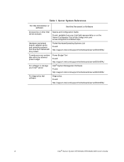
.../server/S5000PAL/ To make sure your system falls within the allowed power budget For software to manage your Intel® server Power Budget Tool Found: http://support.intel.com/support/motherboards/server/S5000PAL/ Intel® System Management Software Found: http://support.intel.com/support/motherboards/server/S5000PAL/ For diagnostics test software Diagnostics Found: http://support.intel.com/support/motherboards/server/S5000PAL/ 2 Intel® Server System SR1550AL/SR1550ALSAS...
.../server/S5000PAL/ To make sure your system falls within the allowed power budget For software to manage your Intel® server Power Budget Tool Found: http://support.intel.com/support/motherboards/server/S5000PAL/ Intel® System Management Software Found: http://support.intel.com/support/motherboards/server/S5000PAL/ For diagnostics test software Diagnostics Found: http://support.intel.com/support/motherboards/server/S5000PAL/ 2 Intel® Server System SR1550AL/SR1550ALSAS...

User Guide
Page 24
...12V standard on the first 20 pins National Semiconductor* PC87427 controller On-board ATI* ES1000 video controller with 16 MB DDR SDRAM Intel® 82563EB dual port controller for 10/100/1000 Mbit/sec Ethernet LAN connectivity • One low profile riser... • Support for up to eight 2.5 inch hot-swap SATA / SAS drives 4 Intel® Server System SR1550AL/SR1550ALSAS User's Guide Table 2 summarizes the features of : • Intel® 5000P Memory Controller Hub (MCH) • Intel® 6321ESB I /O Controll Video LAN Expansion Capabilities Hard Drives Description • 1.700 ...
...12V standard on the first 20 pins National Semiconductor* PC87427 controller On-board ATI* ES1000 video controller with 16 MB DDR SDRAM Intel® 82563EB dual port controller for 10/100/1000 Mbit/sec Ethernet LAN connectivity • One low profile riser... • Support for up to eight 2.5 inch hot-swap SATA / SAS drives 4 Intel® Server System SR1550AL/SR1550ALSAS User's Guide Table 2 summarizes the features of : • Intel® 5000P Memory Controller Hub (MCH) • Intel® 6321ESB I /O Controll Video LAN Expansion Capabilities Hard Drives Description • 1.700 ...

User Guide
Page 25
... to two 650W power supply modules • Six 4-pin fan headers supporting two processor fans, and four system fans • Dedicated non-redundant power supply fan (one per module) • One front panel USB port • One internal USB header providing two USB ports Intel® System Management Software Intel® Server System SR1550AL/SR1550ALSAS User's Guide 5 Table 2.
... to two 650W power supply modules • Six 4-pin fan headers supporting two processor fans, and four system fans • Dedicated non-redundant power supply fan (one per module) • One front panel USB port • One internal USB header providing two USB ports Intel® System Management Software Intel® Server System SR1550AL/SR1550ALSAS User's Guide 5 Table 2.

User Guide
Page 26
... E. Mini Control Panel Bay if Installed) G. Rack Handle H. ChassisComponents 6 Intel® Server System SR1550AL/SR1550ALSAS User's Guide PCI Riser Assembly B. Fan Assembly D. Hard Drive Bays Figure 2. Chassis Component Identification This section helps you can also use the Quick Reference Label provided on the inside of your server system. Mid-plane Board (Active Shown) F. Power Distribution Board L. Power...
... E. Mini Control Panel Bay if Installed) G. Rack Handle H. ChassisComponents 6 Intel® Server System SR1550AL/SR1550ALSAS User's Guide PCI Riser Assembly B. Fan Assembly D. Hard Drive Bays Figure 2. Chassis Component Identification This section helps you can also use the Quick Reference Label provided on the inside of your server system. Mid-plane Board (Active Shown) F. Power Distribution Board L. Power...

User Guide
Page 28
Configuration Jumpers BIOS Select J3H1 3 3 1-2: Force Lower Bank 2-3: Normal Operation (Default) Jumper Name BIOS Select TP02087 Jumper Purpose If pins 1-2 are jumpered, the BIOS in the lower bank will be jumpered on the next reset. These pins should be selected on 2-3 for normal operation. BIOS Select Jumper 8 Intel® Server System SR1550AL/SR1550ALSAS User's Guide Figure 4.
Configuration Jumpers BIOS Select J3H1 3 3 1-2: Force Lower Bank 2-3: Normal Operation (Default) Jumper Name BIOS Select TP02087 Jumper Purpose If pins 1-2 are jumpered, the BIOS in the lower bank will be jumpered on the next reset. These pins should be selected on 2-3 for normal operation. BIOS Select Jumper 8 Intel® Server System SR1550AL/SR1550ALSAS User's Guide Figure 4.

User Guide
Page 29
... normal operation. Figure 5. BMC Force Update Mode If pins 2-3 are jumpered, administrator and user passwords will be jumpered on 1-2 for normal operation. Recovery Jumpers Intel® Server System SR1550AL/SR1550ALSAS User's Guide 9 Password Clear If pins 2-3 are jumpered, BMC Force Update Mode is enabled. These pins should be jumpered on the next reset. These pins...
... normal operation. Figure 5. BMC Force Update Mode If pins 2-3 are jumpered, administrator and user passwords will be jumpered on 1-2 for normal operation. Recovery Jumpers Intel® Server System SR1550AL/SR1550ALSAS User's Guide 9 Password Clear If pins 2-3 are jumpered, BMC Force Update Mode is enabled. These pins should be jumpered on the next reset. These pins...
User Guide
Page 30
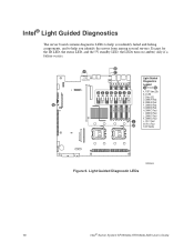
Intel® Light Guided Diagnostics The server board contains diagnostic LEDs to help you identify failed and failing components, and to help you identify the server from among several servers. B A C POST Code LEDs Light Guided Diagnostics Legend A through N DE FGH I . ID LED C. POST Code LEDs B. DIMM D2 Fault L...turn on (amber) only if a failure occurs. Status LED D. DIMM C2 Fault J. Light Guided Diagnostic LEDs AF000644 10 Intel® Server System SR1550AL/SR1550ALSAS User's Guide DIMM B1 Fault DIMM A1 DIMM A2 DIMM B1 DIMM B2 DIMM C1 DIMM C2 DIMM D1 DIMM D2 G. ...
Intel® Light Guided Diagnostics The server board contains diagnostic LEDs to help you identify failed and failing components, and to help you identify the server from among several servers. B A C POST Code LEDs Light Guided Diagnostics Legend A through N DE FGH I . ID LED C. POST Code LEDs B. DIMM D2 Fault L...turn on (amber) only if a failure occurs. Status LED D. DIMM C2 Fault J. Light Guided Diagnostic LEDs AF000644 10 Intel® Server System SR1550AL/SR1550ALSAS User's Guide DIMM B1 Fault DIMM A1 DIMM A2 DIMM B1 DIMM B2 DIMM C1 DIMM C2 DIMM D1 DIMM D2 G. ...

User Guide
Page 31
USB Port 6 K. RJ45 Serial B Connector B. Intel® Remote Management Module NIC (Optional) H. Video L. NIC 1 (10/100/1000 Mb) N. Full Height PCI Add-in Card Slot D. Back Panel Connectors Intel® Server System SR1550AL/SR1550ALSAS User's Guide 11 Keyboard Figure 7. NIC 2 (10/100/1000 Mb) M. Back Panel Connectors A B C D NML K J IH GF E TP02216 A. Mouse C. Power Supply Module 2 (Filler Panel Shown) G. I/O Expansion Module (Optional) I. Low Profile PCI Express* Add-in Card Slot E. Power Supply Module 1 F. USB Port 5 J.
USB Port 6 K. RJ45 Serial B Connector B. Intel® Remote Management Module NIC (Optional) H. Video L. NIC 1 (10/100/1000 Mb) N. Full Height PCI Add-in Card Slot D. Back Panel Connectors Intel® Server System SR1550AL/SR1550ALSAS User's Guide 11 Keyboard Figure 7. NIC 2 (10/100/1000 Mb) M. Back Panel Connectors A B C D NML K J IH GF E TP02216 A. Mouse C. Power Supply Module 2 (Filler Panel Shown) G. I/O Expansion Module (Optional) I. Low Profile PCI Express* Add-in Card Slot E. Power Supply Module 1 F. USB Port 5 J.

