User Guide
Page 30
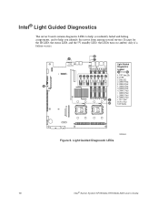
... Legend A through N DE FGH I . DIMM C1 Fault I J K A. CPU 2 Fault N. 5V Standby CPU 2 CPU 1 Socket Socket Figure 6. Light Guided Diagnostic LEDs AF000644 10 Intel® Server System SR1550AL/SR1550ALSAS User's Guide ID LED C. DIMM A2 Fault N F. DIMM C2 Fault J. DIMM B2 Fault H. DIMM D1 Fault K. Intel® Light Guided Diagnostics The server board contains diagnostic LEDs to help you identify...
... Legend A through N DE FGH I . DIMM C1 Fault I J K A. CPU 2 Fault N. 5V Standby CPU 2 CPU 1 Socket Socket Figure 6. Light Guided Diagnostic LEDs AF000644 10 Intel® Server System SR1550AL/SR1550ALSAS User's Guide ID LED C. DIMM A2 Fault N F. DIMM C2 Fault J. DIMM B2 Fault H. DIMM D1 Fault K. Intel® Light Guided Diagnostics The server board contains diagnostic LEDs to help you identify...

User Guide
Page 52
... up the alignment marks on removing the server's cover. 5. See the documentation that came with your server chassis for instructions on the processor and the socket, and insert the processor into the socket. 32 Intel® Server System SR1550AL/SR1550ALSAS User's Guide A B TP02075 Figure... 26. Installing the Processor To install a processor, follow these instructions: 1. Turn off all peripheral devices connected to the server. Raise the CPU load plate (see Figure 25)....
... up the alignment marks on removing the server's cover. 5. See the documentation that came with your server chassis for instructions on the processor and the socket, and insert the processor into the socket. 32 Intel® Server System SR1550AL/SR1550ALSAS User's Guide A B TP02075 Figure... 26. Installing the Processor To install a processor, follow these instructions: 1. Turn off all peripheral devices connected to the server. Raise the CPU load plate (see Figure 25)....

User Guide
Page 53
... 2 1 4 TP02328 Figure 28. Removing the Socket Cover 9. Do no fully tighten one screw before tightening another. 3. Installing the Heat Sink Intel® Server System SR1550AL/SR1550ALSAS User's Guide 33 Note: Retain the protective socket cover for use when removing a processor that will not be replaced. Loosely screw in ...the heat sink over the processor, lining up the four captive screws with the four posts surrounding the processor. 2. Lower the CPU load plate and lower the socket lever completely. Remove the protective socket cover (see Figure 27). Note: Make sure the alignment ...
... 2 1 4 TP02328 Figure 28. Removing the Socket Cover 9. Do no fully tighten one screw before tightening another. 3. Installing the Heat Sink Intel® Server System SR1550AL/SR1550ALSAS User's Guide 33 Note: Retain the protective socket cover for use when removing a processor that will not be replaced. Loosely screw in ...the heat sink over the processor, lining up the four captive screws with the four posts surrounding the processor. 2. Lower the CPU load plate and lower the socket lever completely. Remove the protective socket cover (see Figure 27). Note: Make sure the alignment ...

User Guide
Page 54
...carriers with your server chassis for instructions on the corners of supported hardware. 34 Intel® Server System SR1550AL/SR1550ALSAS User's Guide To avoid possible damage to the server. Turn off all peripheral devices connected to your server chassis for instructions on installing the server's cover. Unplug...7. If it does not pull up easily, twist the heat sink again. Raise the CPU load plate. 11. If installing a replacement processor, see "Installing the Processor". See "Server System References" for an Internet link to break the seal between the heat sink and the ...
...carriers with your server chassis for instructions on the corners of supported hardware. 34 Intel® Server System SR1550AL/SR1550ALSAS User's Guide To avoid possible damage to the server. Turn off all peripheral devices connected to your server chassis for instructions on installing the server's cover. Unplug...7. If it does not pull up easily, twist the heat sink again. Raise the CPU load plate. 11. If installing a replacement processor, see "Installing the Processor". See "Server System References" for an Internet link to break the seal between the heat sink and the ...

User Guide
Page 105
... wires are pinched and that the airflow from your server system, make sure your cables are routed correctly before reinstalling the server system cover. Appendix A: Technical Reference Cable Routing When you add or remove components from the fans is not blocked. A Intel® Remote Management Module (optional) B Intel® RMM NIC Module (optional) C I/O Module (optional) D Power...
... wires are pinched and that the airflow from your server system, make sure your cables are routed correctly before reinstalling the server system cover. Appendix A: Technical Reference Cable Routing When you add or remove components from the fans is not blocked. A Intel® Remote Management Module (optional) B Intel® RMM NIC Module (optional) C I/O Module (optional) D Power...
User Guide
Page 119
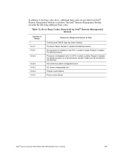
...Intel® Server System SR1550AL/SR1550ALSAS User's Guide 99 Error Beep Codes Generated by Intel® Remote Management Module Number of Beeps 1 1-5-1-1 1-5-2-1 1-5-2-3 1-5-2-4 1-5-4-2 1-5-4-3 1-5-4-4 Reason for Beeps and Action to the beep codes above, additional beep codes are identical. Front-side bus select configuration error. The Intel.... Reseat or replace the failed processor. Processor configuration error or CPU 1 socket is empty. Table 10. Chipset control failure. No processor is installed or the CPU 1 socket is empty. Reseat or replace the failed processor. ...
...Intel® Server System SR1550AL/SR1550ALSAS User's Guide 99 Error Beep Codes Generated by Intel® Remote Management Module Number of Beeps 1 1-5-1-1 1-5-2-1 1-5-2-3 1-5-2-4 1-5-4-2 1-5-4-3 1-5-4-4 Reason for Beeps and Action to the beep codes above, additional beep codes are identical. Front-side bus select configuration error. The Intel.... Reseat or replace the failed processor. Processor configuration error or CPU 1 socket is empty. Table 10. Chipset control failure. No processor is installed or the CPU 1 socket is empty. Reseat or replace the failed processor. ...