
User Guide
Page 11
... 29 Figure 23. Removing Hot-swap Disk Carrier from the Server System 41 Figure 36. Removing the PCIe* Riser Card from the Server System 40 Figure 35. Intel® Integrated Server System SR1550AL 3 Figure 2. Back Panel Connectors 11 Figure 8. Mini Control...Server System 44 Figure 38. Intel® Local Control Panel 18 Figure 13. Installing the PCI-X* Riser Card into the Server System 39 Figure 34. Installing the Front Bezel 26 Figure 19. Installing an Optical Drive Assembly into the Server System 45 Figure 39. ChassisComponents 6 Figure 3. Installing the Memory...
... 29 Figure 23. Removing Hot-swap Disk Carrier from the Server System 41 Figure 36. Removing the PCIe* Riser Card from the Server System 40 Figure 35. Intel® Integrated Server System SR1550AL 3 Figure 2. Back Panel Connectors 11 Figure 8. Mini Control...Server System 44 Figure 38. Intel® Local Control Panel 18 Figure 13. Installing the PCI-X* Riser Card into the Server System 39 Figure 34. Installing the Front Bezel 26 Figure 19. Installing an Optical Drive Assembly into the Server System 45 Figure 39. ChassisComponents 6 Figure 3. Installing the Memory...

User Guide
Page 14
...Cover 26 Removing the Chassis Cover 26 Installing the Server System Cover 27 Removing and Installing the Processor Air Duct 28 Removing the Processor Air Duct 28 Installing the Processor Air Duct 29 Installing and Removing Memory 30 Installing DIMMs ...30 Removing DIMMs ...31 ...Intel® Integrated RAID Activation Key and the RAID Mini DIMM 55 Removing the Intel® Integrated RAID Activation Key and the RAID Mini DIMM ......... 56 Installing and Removing the RAID Battery Backup Unit (BBU 57 Installing the RAID Battery Backup Unit 57 xiv Intel® Server System SR1550AL...
...Cover 26 Removing the Chassis Cover 26 Installing the Server System Cover 27 Removing and Installing the Processor Air Duct 28 Removing the Processor Air Duct 28 Installing the Processor Air Duct 29 Installing and Removing Memory 30 Installing DIMMs ...30 Removing DIMMs ...31 ...Intel® Integrated RAID Activation Key and the RAID Mini DIMM 55 Removing the Intel® Integrated RAID Activation Key and the RAID Mini DIMM ......... 56 Installing and Removing the RAID Battery Backup Unit (BBU 57 Installing the RAID Battery Backup Unit 57 xiv Intel® Server System SR1550AL...

User Guide
Page 24
...430.0mm) wide • 25.76 inches (654.4mm) deep • 37pounds (16.8 kg) - Table 2. Intel® Server System SR1550AL Feature Summary Feature Dimensions Server Board Processor Memory Chipset Peripheral Interfaces I /O Controller Hub External connections: • Stacked PS/2* ports for keyboard and mouse • ... 16 MB DDR SDRAM Intel® 82563EB dual port controller for up to eight 2.5 inch hot-swap SATA / SAS drives 4 Intel® Server System SR1550AL/SR1550ALSAS User's Guide base chassis weight Intel® Server Board S5000PAL Support for up to two Dual-Core Intel®...
...430.0mm) wide • 25.76 inches (654.4mm) deep • 37pounds (16.8 kg) - Table 2. Intel® Server System SR1550AL Feature Summary Feature Dimensions Server Board Processor Memory Chipset Peripheral Interfaces I /O Controller Hub External connections: • Stacked PS/2* ports for keyboard and mouse • ... 16 MB DDR SDRAM Intel® 82563EB dual port controller for up to eight 2.5 inch hot-swap SATA / SAS drives 4 Intel® Server System SR1550AL/SR1550ALSAS User's Guide base chassis weight Intel® Server Board S5000PAL Support for up to two Dual-Core Intel®...

User Guide
Page 49
Turn processor air duct over the processor socket(s). The front edge of this book. See ""Safety Information". 2. Do not remove memory air deflector. See the figure below. Installing the Processor Air Duct Intel® Server System SR1550AL/SR1550ALSAS User's Guide 29 Installing a second processor: remove air dam by sliding slotted holes off duct pins. TP02227 Figure...
Turn processor air duct over the processor socket(s). The front edge of this book. See ""Safety Information". 2. Do not remove memory air deflector. See the figure below. Installing the Processor Air Duct Intel® Server System SR1550AL/SR1550ALSAS User's Guide 29 Installing a second processor: remove air dam by sliding slotted holes off duct pins. TP02227 Figure...

User Guide
Page 50
... Socket DIMM A1 Socket DIMM C1 Socket DIMM C2 Socket DIMM D1 Socket DIMM D2 Socket D A C B TP02072 Figure 24. Installing the Memory 30 Intel® Server System SR1550AL/SR1550ALSAS User's Guide Installing and Removing Memory The silkscreen on the board for the DIMMs displays DIMM A1, DIMM A2, DIMM B1, DIMM B2, DIMM C1, DIMM C2...
... Socket DIMM A1 Socket DIMM C1 Socket DIMM C2 Socket DIMM D1 Socket DIMM D2 Socket D A C B TP02072 Figure 24. Installing the Memory 30 Intel® Server System SR1550AL/SR1550ALSAS User's Guide Installing and Removing Memory The silkscreen on the board for the DIMMs displays DIMM A1, DIMM A2, DIMM B1, DIMM B2, DIMM C1, DIMM C2...
User Guide
Page 99
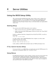
...memory. If You Cannot Access Setup If you might need to enter SETUP In a third condition, when CMOS/NVRAM has been corrupted, you will see "Clearing the CMOS". Except for CMOS and attempt to the "Clear CMOS" position (enabled). If a value cannot be changed for a link to the Intel... BIOS setup screens. Setup Menus Each BIOS Setup menu page contains a number of features. For instructions on the server board to boot. You can be changed if the user has adequate security rights. See "Server System References" for any reason, the feature's value field is inaccessible.
...memory. If You Cannot Access Setup If you might need to enter SETUP In a third condition, when CMOS/NVRAM has been corrupted, you will see "Clearing the CMOS". Except for CMOS and attempt to the "Clear CMOS" position (enabled). If a value cannot be changed for a link to the Intel... BIOS setup screens. Setup Menus Each BIOS Setup menu page contains a number of features. For instructions on the server board to boot. You can be changed if the user has adequate security rights. See "Server System References" for any reason, the feature's value field is inaccessible.

User Guide
Page 101
... the following message to upgrade the BIOS in the BIOS Setup program. Write down the current settings in flash memory. Intel® Server System SR1550AL/SR1550ALSAS User's Guide 81 Pressing causes the following : • On-board system BIOS, including the recovery code, BIOS Setup Utility, and strings. • On-board video BIOS, and other option ROMs...
... the following message to upgrade the BIOS in the BIOS Setup program. Write down the current settings in flash memory. Intel® Server System SR1550AL/SR1550ALSAS User's Guide 81 Pressing causes the following : • On-board system BIOS, including the recovery code, BIOS Setup Utility, and strings. • On-board video BIOS, and other option ROMs...
User Guide
Page 109
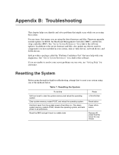
... "Server System References" for assistance. In addition to the server firmware and files, also update any issue, first ensure you are using the latest firmware and files. Intel provides a package called the "Platform Confidence Test" that might occur while you are unable to resolve your server problems... in -depth troubleshooting, attempt first to clear the system memory and reload the operating system Clear system memory, restart POST, and reload the operating system Cold boot reset. If you are using one minute Resetting the System To do this software. For any drivers used for...
... "Server System References" for assistance. In addition to the server firmware and files, also update any issue, first ensure you are using the latest firmware and files. Intel provides a package called the "Platform Confidence Test" that might occur while you are unable to resolve your server problems... in -depth troubleshooting, attempt first to clear the system memory and reload the operating system Clear system memory, restart POST, and reload the operating system Cold boot reset. If you are using one minute Resetting the System To do this software. For any drivers used for...

User Guide
Page 110
... Did you are experiencing is with a specific software application, see "Problems with them. Check the tested memory, and chassis lists, as well as the supported hardware and operating system list. Check the AC cable(s) on the back of the chassis and at the AC source. •...peripheral devices installed correctly? • If the system has a hard disk drive, is a less frequent cause. To check these settings, refer to the tested component lists. 90 Intel® Server System SR1550AL/SR1550ALSAS User's Guide If the problem you press the system power on/off switch on the front panel ...
... Did you are experiencing is with a specific software application, see "Problems with them. Check the tested memory, and chassis lists, as well as the supported hardware and operating system list. Check the AC cable(s) on the back of the chassis and at the AC source. •...peripheral devices installed correctly? • If the system has a hard disk drive, is a less frequent cause. To check these settings, refer to the tested component lists. 90 Intel® Server System SR1550AL/SR1550ALSAS User's Guide If the problem you press the system power on/off switch on the front panel ...

User Guide
Page 112
... • Did you cannot correct the problem, contact your system has one at a time with a reboot between each addition. • Make sure the memory DIMMs comply with the system requirements. • Make sure the memory DIMMs have been populated according to the fan. If your ... • There are installed only below in cards and see if the system boots. If you press the power-on the back of the server board and cause a short. 92 Intel® Server System SR1550AL/SR1550ALSAS User's Guide Specific Problems and Corrective Actions This section provides possible solutions ...
... • Did you cannot correct the problem, contact your system has one at a time with a reboot between each addition. • Make sure the memory DIMMs comply with the system requirements. • Make sure the memory DIMMs have been populated according to the fan. If your ... • There are installed only below in cards and see if the system boots. If you press the power-on the back of the server board and cause a short. 92 Intel® Server System SR1550AL/SR1550ALSAS User's Guide Specific Problems and Corrective Actions This section provides possible solutions ...

User Guide
Page 113
Intel® Server System SR1550AL/SR1550ALSAS User's Guide 93 If you are using a switch box, is fully seated in the server board connector. 3. Verify that the video controller board is it by turning the "Num Lock" function on and off to the correct system? • Are the ...a time with a reboot between each addition. • Make sure the memory DIMMs comply with the system requirements. • Make sure the memory DIMMs have been populated according to the system requirements. • Remove the memory DIMMs and re-seat them . If there are using the onboard video ...
Intel® Server System SR1550AL/SR1550ALSAS User's Guide 93 If you are using a switch box, is fully seated in the server board connector. 3. Verify that the video controller board is it by turning the "Num Lock" function on and off to the correct system? • Are the ...a time with a reboot between each addition. • Make sure the memory DIMMs comply with the system requirements. • Make sure the memory DIMMs have been populated according to the system requirements. • Remove the memory DIMMs and re-seat them . If there are using the onboard video ...

User Guide
Page 118
... codes are supported by BIOS beep codes. Table 8. Please note that can aid in troubleshooting your system manufacturer. Reseat the memory or replace the DIMMs with a description of their use Server Management software to Take Memory error. A table of these beep codes to inform users of Beeps 1, 2, or 3 4 ... the system. POST Error Beep Codes Number of error conditions. Remove all error conditions are not generated after the add-in sleep stats S0 Press ID LED button or use is bing used, the server board may be faulty. 98 Intel® Server System SR1550AL/SR1550ALSAS ...
... codes are supported by BIOS beep codes. Table 8. Please note that can aid in troubleshooting your system manufacturer. Reseat the memory or replace the DIMMs with a description of their use Server Management software to Take Memory error. A table of these beep codes to inform users of Beeps 1, 2, or 3 4 ... the system. POST Error Beep Codes Number of error conditions. Remove all error conditions are not generated after the add-in sleep stats S0 Press ID LED button or use is bing used, the server board may be faulty. 98 Intel® Server System SR1550AL/SR1550ALSAS ...

User Guide
Page 126
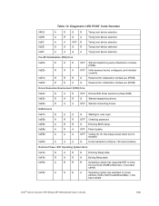
... Diagnostic LED Decoder Description G=Green, R=Red, A=Amber MSB LSB Host Processor 0x10h OFF 0x11h 0x12h 0x13h Chipset 0x21h Memory 0x22h OFF OFF OFF OFF OFF 0x23h 0x24h OFF OFF 0x25h OFF 0x26h 0x27h 0x28h OFF OFF G OFF OFF R...server board Diagnostic LEDs MSB LSB Figure 75. USB Port USB Port Back edge of memory OFF Programming timing parameters in the memory controller G Configuring memory parameters in the memory controller OFF Optimizing memory controller settings G Initializing memory, such as ECC init OFF Testing memory 106 Intel® Server System SR1550AL...
... Diagnostic LED Decoder Description G=Green, R=Red, A=Amber MSB LSB Host Processor 0x10h OFF 0x11h 0x12h 0x13h Chipset 0x21h Memory 0x22h OFF OFF OFF OFF OFF 0x23h 0x24h OFF OFF 0x25h OFF 0x26h 0x27h 0x28h OFF OFF G OFF OFF R...server board Diagnostic LEDs MSB LSB Figure 75. USB Port USB Port Back edge of memory OFF Programming timing parameters in the memory controller G Configuring memory parameters in the memory controller OFF Optimizing memory controller settings G Initializing memory, such as ECC init OFF Testing memory 106 Intel® Server System SR1550AL...
User Guide
Page 129
...Exiting Sleep state A R R R Operating system has requested EFI to close boot services (ExitBootServices ( ) has been called) A R R A Operating system has switched to virtual address mode (SetVirtualAddressMap ( ) has been called) Intel® Server System SR1550AL/SR1550ALSAS User's Guide 109 Diagnostic LED POST ... (PEI) Core 0xE0h 0xE2h 0xE1h 0xE3h R R R OFF Started dispatching early initialization modules (PEIM) R R A OFF Initial memory found, configured, and installed correctly R R R G Reserved for initialization module use (PEIM) R R A G Reserved for...
...Exiting Sleep state A R R R Operating system has requested EFI to close boot services (ExitBootServices ( ) has been called) A R R A Operating system has switched to virtual address mode (SetVirtualAddressMap ( ) has been called) Intel® Server System SR1550AL/SR1550ALSAS User's Guide 109 Diagnostic LED POST ... (PEI) Core 0xE0h 0xE2h 0xE1h 0xE3h R R R OFF Started dispatching early initialization modules (PEIM) R R A OFF Initial memory found, configured, and installed correctly R R R G Reserved for initialization module use (PEIM) R R A G Reserved for...