
Service Guide
Page 9
... Chapter 1: Server System Contents and References 1 Server System Contents ...1 Intel® Server System SR1625UR Contents 1 Intel® Server System SR1625URSAS Contents 2 Additional Information and Software 3 Chapter 2: Server System Features 5 Server System Feature Overview 6 Server System Components 9 Intel® Light-Guided Diagnostics 10 Server Board Components 14 Configuration Jumpers 16 Front of Server System ...18 Peripheral Devices ...18 Control Panel ...19 Bezels ...23 Rear of Server System ...24 Back Panel Connectors 25 SAS/SATA Midplanes...
... Chapter 1: Server System Contents and References 1 Server System Contents ...1 Intel® Server System SR1625UR Contents 1 Intel® Server System SR1625URSAS Contents 2 Additional Information and Software 3 Chapter 2: Server System Features 5 Server System Feature Overview 6 Server System Components 9 Intel® Light-Guided Diagnostics 10 Server Board Components 14 Configuration Jumpers 16 Front of Server System ...18 Peripheral Devices ...18 Control Panel ...19 Bezels ...23 Rear of Server System ...24 Back Panel Connectors 25 SAS/SATA Midplanes...

Service Guide
Page 10
...Installing the Front Bezel 40 Removing and Installing the System Cover 41 Removing the Server System Cover 41 Installing the Server System Cover 42 Removing and Installing the PCI Riser Assembly...SAS/SATA Hard Disk Drive 61 Installing and Removing a Slimline Optical Drive 62 Installing a Slimline Optical Drive 62 Removing a Slimline Optical Drive 63 Installing and Removing the I/O Expansion Module 64 Installing the I/O Expansion Module 64 Removing the I/O Expansion Module(s 65 Installing and Removing the Intel® Remote Management Module 3 66 x Intel® Server System SR1625UR...
...Installing the Front Bezel 40 Removing and Installing the System Cover 41 Removing the Server System Cover 41 Installing the Server System Cover 42 Removing and Installing the PCI Riser Assembly...SAS/SATA Hard Disk Drive 61 Installing and Removing a Slimline Optical Drive 62 Installing a Slimline Optical Drive 62 Removing a Slimline Optical Drive 63 Installing and Removing the I/O Expansion Module 64 Installing the I/O Expansion Module 64 Removing the I/O Expansion Module(s 65 Installing and Removing the Intel® Remote Management Module 3 66 x Intel® Server System SR1625UR...

Service Guide
Page 15
... Cover 54 Figure 39. Installing the Heatsink 56 Intel® Server System SR1625UR Service Guide xv Active Midplane 12 Figure 6. Intel® Light-Guided Diagnostic LEDs - Intel® Light-Guided Diagnostic LEDs - Mini Control ...Server System 44 Figure 29. Intel® Light-Guided Diagnostic LEDs - Removing PCI Riser Assembly from the Server System 43 Figure 28. Server System Components 9 Figure 3. Server Board Connector and Component Locations 15 Figure 8. Hot-swap SAS/SATA Backplane Front Side Components 29 Figure 18. Intel® Server System SR1625UR...
... Cover 54 Figure 39. Installing the Heatsink 56 Intel® Server System SR1625UR Service Guide xv Active Midplane 12 Figure 6. Intel® Light-Guided Diagnostic LEDs - Intel® Light-Guided Diagnostic LEDs - Mini Control ...Server System 44 Figure 29. Intel® Light-Guided Diagnostic LEDs - Removing PCI Riser Assembly from the Server System 43 Figure 28. Server System Components 9 Figure 3. Server Board Connector and Component Locations 15 Figure 8. Hot-swap SAS/SATA Backplane Front Side Components 29 Figure 18. Intel® Server System SR1625UR...

Service Guide
Page 19
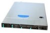
The contents of the Intel® Server System SR1625UR: • Intel® Server System SR1625UR (Passive system) • Intel® Server System SR1625URSAS (Active system) Unless noted otherwise, all references to the Intel® Server System SR1625UR refer to both product codes. Intel® Server System SR1625UR Contents Your Intel® Server System SR1625UR (passive system) ships with the Intel® Server Board S5520UR. For information about the server board, see Intel® Server Board S5520UR Technical Product Specification. 1 Server System Contents and References...
The contents of the Intel® Server System SR1625UR: • Intel® Server System SR1625UR (Passive system) • Intel® Server System SR1625URSAS (Active system) Unless noted otherwise, all references to the Intel® Server System SR1625UR refer to both product codes. Intel® Server System SR1625UR Contents Your Intel® Server System SR1625UR (passive system) ships with the Intel® Server Board S5520UR. For information about the server board, see Intel® Server Board S5520UR Technical Product Specification. 1 Server System Contents and References...
Service Guide
Page 20
...Intel® Server Board S5520UR, installed in the server system • One 650-W power supply, installed in the server system • Full-length and full-height PCI Express* riser card assembly, installed in the server system • Processor air duct, installed in the server system • Two processor heatsinks, installed in the server system • Active SAS/SATA midplane, installed in the server system...box • Attention document, in the server system product box • Quick Start User's Guide, in the server system product box 2 Intel® Server System SR1625UR Service Guide
...Intel® Server Board S5520UR, installed in the server system • One 650-W power supply, installed in the server system • Full-length and full-height PCI Express* riser card assembly, installed in the server system • Processor air duct, installed in the server system • Two processor heatsinks, installed in the server system • Active SAS/SATA midplane, installed in the server system...box • Attention document, in the server system product box • Quick Start User's Guide, in the server system product box 2 Intel® Server System SR1625UR Service Guide

Service Guide
Page 25
Table 2. Intel® Server System SR1625UR Feature Summary Feature Peripheral Interfaces Video LAN Expansion Capabilities Hard Drives Peripherals Control Panel Description External connections: • DB-15 video connector (back) • RJ-45 serial Port A connector • Two RJ-45 10/100/1000 Mb network connections • Four USB... to eight 2.5 inch hot-swap SATA/SAS drives with mini control panel • Up to six 2.5 inch hot-swap SATA/SAS drives with standard control panel or Intel® Local Control Panel • Intel® Embedded Server RAID Technology II with SW RAID levels ...
Table 2. Intel® Server System SR1625UR Feature Summary Feature Peripheral Interfaces Video LAN Expansion Capabilities Hard Drives Peripherals Control Panel Description External connections: • DB-15 video connector (back) • RJ-45 serial Port A connector • Two RJ-45 10/100/1000 Mb network connections • Four USB... to eight 2.5 inch hot-swap SATA/SAS drives with mini control panel • Up to six 2.5 inch hot-swap SATA/SAS drives with standard control panel or Intel® Local Control Panel • Intel® Embedded Server RAID Technology II with SW RAID levels ...

Service Guide
Page 36
... 59. Note: Drives can support: • Up to eight 2.5 inch hard drives with the standard control panel or the Intel® Local Control Panel. Rack Handles B. Note: The Intel® Server System SR1625UR does not support all SAS or Serial ATA (SATA) hard drives. For a web link to six 2.5 inch hard drives with the mini control...
... 59. Note: Drives can support: • Up to eight 2.5 inch hard drives with the standard control panel or the Intel® Local Control Panel. Rack Handles B. Note: The Intel® Server System SR1625UR does not support all SAS or Serial ATA (SATA) hard drives. For a web link to six 2.5 inch hard drives with the mini control...

Service Guide
Page 39
...blinking green light indicates hard disk drive activity (SAS or SATA). Solid amber indicates a critical or non-recoverable condition. Turns on /off the system identification LED. Puts the server in ACPI S4 or S5 state. Standard Control Panel Intel® Local Control Panel The following diagram ... on installing the standard control panel, see "Replacing the Control Panel" on the Intel® Local Control Panel. Intel® Server System SR1625UR Service Guide 21 J. Reboots and initializes the system. Blinking green light indicates network activity. K. D. No light indicates...
...blinking green light indicates hard disk drive activity (SAS or SATA). Solid amber indicates a critical or non-recoverable condition. Turns on /off the system identification LED. Puts the server in ACPI S4 or S5 state. Standard Control Panel Intel® Local Control Panel The following diagram ... on installing the standard control panel, see "Replacing the Control Panel" on the Intel® Local Control Panel. Intel® Server System SR1625UR Service Guide 21 J. Reboots and initializes the system. Blinking green light indicates network activity. K. D. No light indicates...
Service Guide
Page 41
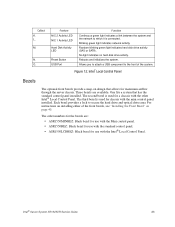
... numbers for the bezels are available. M. Reboots and initializes the system. Figure 12. Intel® Server System SR1625UR Service Guide 23 Blinking green light indicates network activity. Random blinking green light indicates hard disk drive activity (SAS or SATA). For instructions on installing either of the system. N. Intel® Local Control Panel Bezels The optional front bezels provide...
... numbers for the bezels are available. M. Reboots and initializes the system. Figure 12. Intel® Server System SR1625UR Service Guide 23 Blinking green light indicates network activity. Random blinking green light indicates hard disk drive activity (SAS or SATA). For instructions on installing either of the system. N. Intel® Local Control Panel Bezels The optional front bezels provide...

Service Guide
Page 45
.../SAS Midplane Components Intel® Server System SR1625UR Service Guide 27 SAS/SATA Midplanes The midplane serves as an interconnect, routing drive control signals from an add-in card to the hot-swap backplane. Passive Midplane The passive midplane s used as the primary interface between the server... board, the hot-swap backplane, and the control panel. The following diagram show the location for this system: • Passive SATA/SAS • Active SAS/SAS RAID. Backplane Connector Figure 15. Fan 5 Connector ...
.../SAS Midplane Components Intel® Server System SR1625UR Service Guide 27 SAS/SATA Midplanes The midplane serves as an interconnect, routing drive control signals from an add-in card to the hot-swap backplane. Passive Midplane The passive midplane s used as the primary interface between the server... board, the hot-swap backplane, and the control panel. The following diagram show the location for this system: • Passive SATA/SAS • Active SAS/SAS RAID. Backplane Connector Figure 15. Fan 5 Connector ...

Service Guide
Page 46
B A C D E F G H I . Fan 6 Power Connector E. Fan 3 Power Connector I J L K AF002790 A. Active SAS/SAS RAID Midplane Components 28 Intel® Server System SR1625UR Service Guide Mini-DIMM Connector D. Fan 4 Power Connector H. Fan 2 Power Connector K. Fan 5 Power Connector F. RAID Battery Backup Unit Connector B. Fan 1 Power Connector J. RAID Activation Key ...
B A C D E F G H I . Fan 6 Power Connector E. Fan 3 Power Connector I J L K AF002790 A. Active SAS/SAS RAID Midplane Components 28 Intel® Server System SR1625UR Service Guide Mini-DIMM Connector D. Fan 4 Power Connector H. Fan 2 Power Connector K. Fan 5 Power Connector F. RAID Battery Backup Unit Connector B. Fan 1 Power Connector J. RAID Activation Key ...

Service Guide
Page 47
... drive bay inside the chassis. Power Connector C. Card Edge Connectors to Midplane D. 10-pin Control Panel Connector Figure 18. Slimline Optical Device Connector B. Hot-swap SAS/SATA Backplane Back Side Components Intel® Server System SR1625UR Service Guide 29 SAS/SATA hot-swap Connectors Figure 17. A B C AF002809 A.
... drive bay inside the chassis. Power Connector C. Card Edge Connectors to Midplane D. 10-pin Control Panel Connector Figure 18. Slimline Optical Device Connector B. Hot-swap SAS/SATA Backplane Back Side Components Intel® Server System SR1625UR Service Guide 29 SAS/SATA hot-swap Connectors Figure 17. A B C AF002809 A.

Service Guide
Page 77
...Software" on page 3 for future use older style drive carriers. Intel® Server System SR1625UR Service Guide 59 Note: The server system does not support all hard drives. Press in on the black lever and slide the carrier out from the Server System 3. Pull out on the green latch (at the front of the... hard drive carrier) to release the carrier (see letter "B" in Figure 44). When configured with the Standard control panel or Intel® Local Control Panel, up to eight hot-swap SAS or SATA ...
...Software" on page 3 for future use older style drive carriers. Intel® Server System SR1625UR Service Guide 59 Note: The server system does not support all hard drives. Press in on the black lever and slide the carrier out from the Server System 3. Pull out on the green latch (at the front of the... hard drive carrier) to release the carrier (see letter "B" in Figure 44). When configured with the Standard control panel or Intel® Local Control Panel, up to eight hot-swap SAS or SATA ...

Service Guide
Page 79
...that attach the hard drive to lock the drive assembly into the screw locations on the green latch at the front of the following: - Intel® Server System SR1625UR Service Guide 61 To install the replacement drive, see letter "B" in Figure 47).) A B AF002874 Figure 47. Install Drive Assemby into place... the hard drive into place (see "Installing a Hot-swap SAS/SATA Hard Disk Drive" on the black lever to lock the drive assembly into the Server System Removing a Hot-swap SAS/SATA Hard Disk Drive To remove a hot-swap SAS/SATA hard disk drive, follow these steps: 1. Do one ...
...that attach the hard drive to lock the drive assembly into the screw locations on the green latch at the front of the following: - Intel® Server System SR1625UR Service Guide 61 To install the replacement drive, see letter "B" in Figure 47).) A B AF002874 Figure 47. Install Drive Assemby into place... the hard drive into place (see "Installing a Hot-swap SAS/SATA Hard Disk Drive" on the black lever to lock the drive assembly into the Server System Removing a Hot-swap SAS/SATA Hard Disk Drive To remove a hot-swap SAS/SATA hard disk drive, follow these steps: 1. Do one ...

Service Guide
Page 125
...Arabic, Chinese (Simplified)): Service Pack Level or Kernel Revision: Distribution (OEM/Retail Intel® Server System SR1625UR Service Guide 107 Add-in adapters (Example: NICs, Management Adapters, Serial Expansion... Cards, PCI-Express* Adapters, RAID Controllers, SCSI Controllers, etc.): Type Slot Manufacturer Model Firmware Third party hardware (Example: Example: KVM, Chassis, etc): Description/Use Manufacturer Model Firmware Storage Devices (Example: SCSI, SATA, SAS...
...Arabic, Chinese (Simplified)): Service Pack Level or Kernel Revision: Distribution (OEM/Retail Intel® Server System SR1625UR Service Guide 107 Add-in adapters (Example: NICs, Management Adapters, Serial Expansion... Cards, PCI-Express* Adapters, RAID Controllers, SCSI Controllers, etc.): Type Slot Manufacturer Model Firmware Third party hardware (Example: Example: KVM, Chassis, etc): Description/Use Manufacturer Model Firmware Storage Devices (Example: SCSI, SATA, SAS...

Quick Start Guide
Page 1
...MB, 240-pin DDR3 800/1066/1333-MT/s DIMMs. • Hard Disk Drives: SATA/SAS • Rack Mount Kit (EIA 310-D compliant) For a complete list of alignment notch. Place your Intel® Server System for complete safety information. Before proceeding further, check your Intel® Server... chassis with your Intel® Server System SR1625UR (Product Codes: SR1625UR and SR1625URSAS) and install components. Intel® Server System SR1625UR Quick Start User's Guide Thank you for future use the Server Configurator Tool available at: http://serverconfigurator.intel.com/default.aspx Chan...
...MB, 240-pin DDR3 800/1066/1333-MT/s DIMMs. • Hard Disk Drives: SATA/SAS • Rack Mount Kit (EIA 310-D compliant) For a complete list of alignment notch. Place your Intel® Server System for complete safety information. Before proceeding further, check your Intel® Server... chassis with your Intel® Server System SR1625UR (Product Codes: SR1625UR and SR1625URSAS) and install components. Intel® Server System SR1625UR Quick Start User's Guide Thank you for future use the Server Configurator Tool available at: http://serverconfigurator.intel.com/default.aspx Chan...