Hardware User Guide
Page 8
... overview of the RAID Controller SRCU42E. • Chapter 2, "Hardware Installation," describes the procedures for installing the RAID Controller SRCU42E. • Chapter 3, "Intel® RAID Controller SRCU42E Technical Reference," describes the technical specifications for the RAID Controller SRCU42E. • Chapter A, "Glossary of the software drivers, see the Intel RAID Software User's Guide. For information about how to configure the RAID Controller SRCU42E, and for the Intel® RAID Controller SRCU42E. Related Publications Intel® RAID Software User's Guide...
... overview of the RAID Controller SRCU42E. • Chapter 2, "Hardware Installation," describes the procedures for installing the RAID Controller SRCU42E. • Chapter 3, "Intel® RAID Controller SRCU42E Technical Reference," describes the technical specifications for the RAID Controller SRCU42E. • Chapter A, "Glossary of the software drivers, see the Intel RAID Software User's Guide. For information about how to configure the RAID Controller SRCU42E, and for the Intel® RAID Controller SRCU42E. Related Publications Intel® RAID Software User's Guide...

Hardware User Guide
Page 25
2.4 After You Have Installed the RAID Controller After installation, you about the configuration options and how to set them on your RAID Controller SRCU42E. After You Have Installed the RAID Controller 25 The Intel RAID Software User's Guide instructs you must configure the RAID Controller SRCU42E and install the operating system driver.
2.4 After You Have Installed the RAID Controller After installation, you about the configuration options and how to set them on your RAID Controller SRCU42E. After You Have Installed the RAID Controller 25 The Intel RAID Software User's Guide instructs you must configure the RAID Controller SRCU42E and install the operating system driver.
Hardware User Guide
Page 27
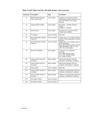
Table 3-1Intel® RAID Controller SRCU42E Headers and Connectors Connector Description Type Comments J1 Write Pending Indicator 2-pin header Connector for diagnostic purposes. J6 SCSI Termination Enable 3-pin connector Jumper pins 2-3 to enable software Channel 0 control of SCSI termination via drive detection. Connection is optional. J14 External SCSI Channel 1 68-pin header External very-high density SCSI bus connector connector...
Table 3-1Intel® RAID Controller SRCU42E Headers and Connectors Connector Description Type Comments J1 Write Pending Indicator 2-pin header Connector for diagnostic purposes. J6 SCSI Termination Enable 3-pin connector Jumper pins 2-3 to enable software Channel 0 control of SCSI termination via drive detection. Connection is optional. J14 External SCSI Channel 1 68-pin header External very-high density SCSI bus connector connector...
Hardware User Guide
Page 32
... system driver that provides a device connection to direct the operation of termination resistors. Ultra SCSI, Ultra2 SCSI, Ultra160 SCSI, and Ultra320 SCSI require active termination. These devices are connected together using an unshielded ribbon cable. NonVolatile Random...RAID controller to transfer information to and from devices attached to the way a computer is directly accessible by the CPU (usually synonymous with each signal transfer (as opposed to a common ground). Basic Input/Output System. The SCSI BIOS on the mainboard of the system BIOS. or the software...
... system driver that provides a device connection to direct the operation of termination resistors. Ultra SCSI, Ultra2 SCSI, Ultra160 SCSI, and Ultra320 SCSI require active termination. These devices are connected together using an unshielded ribbon cable. NonVolatile Random...RAID controller to transfer information to and from devices attached to the way a computer is directly accessible by the CPU (usually synonymous with each signal transfer (as opposed to a common ground). Basic Input/Output System. The SCSI BIOS on the mainboard of the system BIOS. or the software...