Product Guide
Page 3
... loss of this manual: CAUTION Cautions warn the user about board layout, component installation, BIOS update, and regulatory requirements for Intended Applications All Intel Desktop Boards are evaluated as follows: 1 Desktop Board Features: a summary of product features 2 Installing and Replacing Desktop Board Components: instructions on how to install the Desktop Board and other hardware components 3 Updating the BIOS: instructions on how to update the BIOS A Error Messages and Indicators: information about BIOS error messages and beep codes B Regulatory Compliance: safety...
... loss of this manual: CAUTION Cautions warn the user about board layout, component installation, BIOS update, and regulatory requirements for Intended Applications All Intel Desktop Boards are evaluated as follows: 1 Desktop Board Features: a summary of product features 2 Installing and Replacing Desktop Board Components: instructions on how to install the Desktop Board and other hardware components 3 Updating the BIOS: instructions on how to update the BIOS A Error Messages and Indicators: information about BIOS error messages and beep codes B Regulatory Compliance: safety...
Product Guide
Page 5
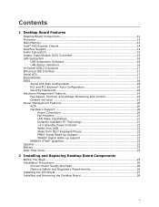
...Intel® P43 Express Chipset 14 Graphics Support 14 Audio Subsystem 15 Legacy Input/Output (I/O) Controller 15 LAN Subsystem 16 LAN Subsystem Software 16 LAN Status Indicators 16 Hi-Speed USB 2.0 Support 17 Enhanced IDE Interface 17 Serial ATA...17 Expandability...17 BIOS ...18 Serial ATA Auto Configuration 18 PCI and PCI Express* Auto Configuration 18 Security Passwords 18 Hardware Management Features 19 Fan Speed, Thermal, and Voltage Monitoring and Control 19 Chassis Intrusion 19 Power Management Features 20 ACPI ...20 Hardware Support 20 Power Connectors 20 Fan Headers...
...Intel® P43 Express Chipset 14 Graphics Support 14 Audio Subsystem 15 Legacy Input/Output (I/O) Controller 15 LAN Subsystem 16 LAN Subsystem Software 16 LAN Status Indicators 16 Hi-Speed USB 2.0 Support 17 Enhanced IDE Interface 17 Serial ATA...17 Expandability...17 BIOS ...18 Serial ATA Auto Configuration 18 PCI and PCI Express* Auto Configuration 18 Security Passwords 18 Hardware Management Features 19 Fan Speed, Thermal, and Voltage Monitoring and Control 19 Chassis Intrusion 19 Power Management Features 20 ACPI ...20 Hardware Support 20 Power Connectors 20 Fan Headers...
Product Guide
Page 6
... PCI Express x16 Card 40 Connecting the IDE Cable 41 Connecting Serial ATA (SATA) Cables 43 Connecting to Internal Headers and Connectors 44 HD Audio Link Header 45 S/PDIF Connector 45 Chassis Intrusion Header 45 Front Panel HD Audio Header 46 USB 2.0 Headers 46 Serial Port Header 47 Front Panel Header 47 Alternate Front Panel Power LED Header 47 IEEE 1394a Header 48 Connecting to the Audio System 48 Connecting Chassis Fan and Power Supply Cables 49 Chassis Fan Cables 49 Power Supply Cables 50 Setting the BIOS Configuration Jumper 51 Clearing Passwords 52 3 Updating the BIOS...
... PCI Express x16 Card 40 Connecting the IDE Cable 41 Connecting Serial ATA (SATA) Cables 43 Connecting to Internal Headers and Connectors 44 HD Audio Link Header 45 S/PDIF Connector 45 Chassis Intrusion Header 45 Front Panel HD Audio Header 46 USB 2.0 Headers 46 Serial Port Header 47 Front Panel Header 47 Alternate Front Panel Power LED Header 47 IEEE 1394a Header 48 Connecting to the Audio System 48 Connecting Chassis Fan and Power Supply Cables 49 Chassis Fan Cables 49 Power Supply Cables 50 Setting the BIOS Configuration Jumper 51 Clearing Passwords 52 3 Updating the BIOS...
Product Guide
Page 7
...-free 2LI Board 70 Restriction of the +5 V Standby Power Indicator 22 4. LAN Status LEDs 16 3. Intel Desktop Board DP43TF Mounting Screw Hole Locations 28 6. Lift the Socket Lever 29 7. Remove the Protective Socket Cover 30 9. Dual Channel Memory Configuration with Two DIMMs 34 14. Internal Headers and Connectors 44 23. Location of the Chassis Fan Headers 49 25. Audio Jack Retasking Support 15 4. Front Panel Audio Header Signal Names 46 9. Installing the I/O Shield 27 5. Location of the BIOS Configuration Jumper Block 51 27. Intel Desktop Board...
...-free 2LI Board 70 Restriction of the +5 V Standby Power Indicator 22 4. LAN Status LEDs 16 3. Intel Desktop Board DP43TF Mounting Screw Hole Locations 28 6. Lift the Socket Lever 29 7. Remove the Protective Socket Cover 30 9. Dual Channel Memory Configuration with Two DIMMs 34 14. Internal Headers and Connectors 44 23. Location of the Chassis Fan Headers 49 25. Audio Jack Retasking Support 15 4. Front Panel Audio Header Signal Names 46 9. Installing the I/O Shield 27 5. Location of the BIOS Configuration Jumper Block 51 27. Intel Desktop Board...

Product Guide
Page 9
... 240-pin, DDR2 1.8 V SDRAM Dual Inline Memory Module (DIMM) sockets • 800/667 MHz single or dual channel DDR2 SDRAM interface • Support for an Intel® processor in cards Onboard subsystem, featuring: • Independent 6-channel (5.1) audio streams • 2-channel stereo audio streams via an onboard header • Intel® High Definition Audio (Intel® HD Audio) interface • RealTek* ALC888VC audio codec • Onboard 3-pin S/PDIF output connector Expansion Capabilities Legacy I/O Support • One PCI Express 2.0 x16 connector • Three PCI Express...
... 240-pin, DDR2 1.8 V SDRAM Dual Inline Memory Module (DIMM) sockets • 800/667 MHz single or dual channel DDR2 SDRAM interface • Support for an Intel® processor in cards Onboard subsystem, featuring: • Independent 6-channel (5.1) audio streams • 2-channel stereo audio streams via an onboard header • Intel® High Definition Audio (Intel® HD Audio) interface • RealTek* ALC888VC audio codec • Onboard 3-pin S/PDIF output connector Expansion Capabilities Legacy I/O Support • One PCI Express 2.0 x16 connector • Three PCI Express...
Product Guide
Page 10
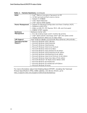
...; 32 Mbit symmetrical flash memory device • Support for SMBIOS • Intel® Rapid BIOS Boot • Intel® Express BIOS Update Power Management • Support for Advanced Configuration and Power Interface (ACPI) • Suspend to RAM (STR) • Wake on USB, PCI, PCI Express, PS/2, LAN, and front panel • ENERGY STAR* capable Hardware Management Hardware monitor with: • Four fan sensing inputs used to monitor fan activity • Intel® Quiet System Technology (Intel® QST) fan speed control LAN Support • Voltage sensing to detect...
...; 32 Mbit symmetrical flash memory device • Support for SMBIOS • Intel® Rapid BIOS Boot • Intel® Express BIOS Update Power Management • Support for Advanced Configuration and Power Interface (ACPI) • Suspend to RAM (STR) • Wake on USB, PCI, PCI Express, PS/2, LAN, and front panel • ENERGY STAR* capable Hardware Management Hardware monitor with: • Four fan sensing inputs used to monitor fan activity • Intel® Quiet System Technology (Intel® QST) fan speed control LAN Support • Voltage sensing to detect...
Product Guide
Page 13
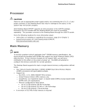
... configure the memory controller for : ⎯ Non-ECC, 1.8 V, DDR2 800/667 MHz memory ⎯ Serial Presence Detect (SPD) memory only ⎯ Unbuffered, non-registered single- Desktop Board Features Processor CAUTION Failure to use an appropriate power supply and/or not connecting the 12 V (2 x 2 pin) power connector to the Desktop Board may not function properly. Processors are not included with the Desktop Board and must be populated with all applicable Intel ® SDRAM memory specifications, the board...
... configure the memory controller for : ⎯ Non-ECC, 1.8 V, DDR2 800/667 MHz memory ⎯ Serial Presence Detect (SPD) memory only ⎯ Unbuffered, non-registered single- Desktop Board Features Processor CAUTION Failure to use an appropriate power supply and/or not connecting the 12 V (2 x 2 pin) power connector to the Desktop Board may not function properly. Processors are not included with the Desktop Board and must be populated with all applicable Intel ® SDRAM memory specifications, the board...

Product Guide
Page 15
... compatible with serialized IRQ support for the front panel and back panel audio jacks. Desktop Board Features Audio Subsystem The onboard audio subsystem consists of the following: • Intel ICH10 I /O controller features the following locations for more information about: • Audio drivers and utilities http://support.intel.com/support/motherboards/desktop/ • Location of the onboard audio headers, Figure 22 on page 48 Table 3 lists the supported functions for PCI systems • PS/2-style mouse and keyboard interfaces • Intelligent power...
... compatible with serialized IRQ support for the front panel and back panel audio jacks. Desktop Board Features Audio Subsystem The onboard audio subsystem consists of the following: • Intel ICH10 I /O controller features the following locations for more information about: • Audio drivers and utilities http://support.intel.com/support/motherboards/desktop/ • Location of the onboard audio headers, Figure 22 on page 48 Table 3 lists the supported functions for PCI systems • PS/2-style mouse and keyboard interfaces • Intelligent power...

Product Guide
Page 16
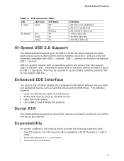
... LAN. Figure 2. Intel Desktop Board DP43TF Product Guide LAN Subsystem The LAN subsystem includes: • Intel® ICH10 • Intel 82567V Gigabit (10/100/1000 Mb/s) Ethernet LAN controller • RJ-45 LAN connector with integrated status LEDs The subsystem features: • CSMA/CD protocol engine • LAN connect interface between ICH10 and the LAN controller • PCI Express power management For information about LAN software and drivers go to http://support.intel.com/support/motherboards/desktop LAN Subsystem Software For LAN software...
... LAN. Figure 2. Intel Desktop Board DP43TF Product Guide LAN Subsystem The LAN subsystem includes: • Intel® ICH10 • Intel 82567V Gigabit (10/100/1000 Mb/s) Ethernet LAN controller • RJ-45 LAN connector with integrated status LEDs The subsystem features: • CSMA/CD protocol engine • LAN connect interface between ICH10 and the LAN controller • PCI Express power management For information about LAN software and drivers go to http://support.intel.com/support/motherboards/desktop LAN Subsystem Software For LAN software...
Product Guide
Page 17
.... This may be required to three internal headers) via ICH10, connecting one device per channel. The interface supports: • Up to USB 1.1 operation. Expandability For system expansion, the Desktop Board provides the following expansion slots: • One PCI Express 2.0 x16 connector (also compatible with USB 1.1 devices. Desktop Board Features Table 4. Disabling Hi-Speed USB in cards) • Three PCI Express 1.1 x1 connectors • Three PCI bus connectors 17 Enhanced IDE Interface The board's IDE interface handles the exchange of information between...
.... This may be required to three internal headers) via ICH10, connecting one device per channel. The interface supports: • Up to USB 1.1 operation. Expandability For system expansion, the Desktop Board provides the following expansion slots: • One PCI Express 2.0 x16 connector (also compatible with USB 1.1 devices. Desktop Board Features Table 4. Disabling Hi-Speed USB in cards) • Three PCI Express 1.1 x1 connectors • Three PCI bus connectors 17 Enhanced IDE Interface The board's IDE interface handles the exchange of information between...
Product Guide
Page 18
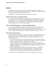
... access to access Setup. You can be accessed and who can be set , you can boot the computer. For instructions on resetting the password, see Clearing Passwords on whether the supervisor or user password was entered. • Setting a user password restricts who can enter either the supervisor password or the user password to view and change all Setup options. Intel Desktop Board DP43TF Product Guide BIOS The BIOS provides the Power-On Self-Test (POST), the BIOS Setup program, the PCI/PCI Express auto-configuration utilities, and the video BIOS. The BIOS is booted...
... access to access Setup. You can be accessed and who can be set , you can boot the computer. For instructions on resetting the password, see Clearing Passwords on whether the supervisor or user password was entered. • Setting a user password restricts who can enter either the supervisor password or the user password to view and change all Setup options. Intel Desktop Board DP43TF Product Guide BIOS The BIOS provides the Power-On Self-Test (POST), the BIOS Setup program, the PCI/PCI Express auto-configuration utilities, and the video BIOS. The BIOS is booted...
Product Guide
Page 20
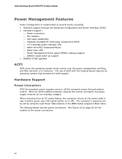
... Support Power Connectors ATX12V-compliant power supplies can be set by using the Last Power State feature in before power was in the BIOS Setup program's Boot menu. The computer's response can turn off the computer power through the Advanced Configuration and Power Interface (ACPI) • Hardware support: ⎯ Power connectors ⎯ Fan headers ⎯ LAN wake capabilities ⎯ Instantly Available PC technology (Suspend to RAM) ⎯ +5 V standby power indicator LED ⎯ Wake from PS/2 Keyboard/Mouse ⎯ Wake from an AC power failure...
... Support Power Connectors ATX12V-compliant power supplies can be set by using the Last Power State feature in before power was in the BIOS Setup program's Boot menu. The computer's response can turn off the computer power through the Advanced Configuration and Power Interface (ACPI) • Hardware support: ⎯ Power connectors ⎯ Fan headers ⎯ LAN wake capabilities ⎯ Instantly Available PC technology (Suspend to RAM) ⎯ +5 V standby power indicator LED ⎯ Wake from PS/2 Keyboard/Mouse ⎯ Wake from an AC power failure...

Product Guide
Page 21
... fan speed according to support the standard Instantly Available (ACPI S3 sleep state) configuration. If the computer has a dual-colored power LED on when the computer is in the ACPI S0 state. • The fans are on the front panel, the sleep state is in power management and can damage the power supply. When signaled by the LED turning amber. The Desktop Board has a 4-pin processor fan header, two 3-pin chassis fan headers, and one 4-pin chassis fan header. While in memory. Desktop Board Features Fan Headers...
... fan speed according to support the standard Instantly Available (ACPI S3 sleep state) configuration. If the computer has a dual-colored power LED on when the computer is in the ACPI S0 state. • The fans are on the front panel, the sleep state is in power management and can damage the power supply. When signaled by the LED turning amber. The Desktop Board has a 4-pin processor fan header, two 3-pin chassis fan headers, and one 4-pin chassis fan header. While in memory. Desktop Board Features Fan Headers...
Product Guide
Page 25
... Desktop Board • Install and remove a processor • Install and remove memory • Install and remove a PCI Express x16 card • Connect the IDE and Serial ATA cables • Connect to the internal headers • Connect to operate even though the front panel power button is not available, you open the computer or perform any of the computer chassis. 25 Some circuitry on the board can continue to the onboard audio system • Connect chassis fan and power supply cables • Set the BIOS configuration jumper • Clear passwords • Replace...
... Desktop Board • Install and remove a processor • Install and remove memory • Install and remove a PCI Express x16 card • Connect the IDE and Serial ATA cables • Connect to the internal headers • Connect to operate even though the front panel power button is not available, you open the computer or perform any of the computer chassis. 25 Some circuitry on the board can continue to the onboard audio system • Connect chassis fan and power supply cables • Set the BIOS configuration jumper • Clear passwords • Replace...

Product Guide
Page 33
... the Processor Fan Heat Sink Cable Removing the Processor For instructions on how to remove the processor fan heat sink and processor, refer to the 4-pin processor fan header (see Figure 12). However, since a fan with a 3-pin connector (Figure 12, B) can be used. however, a fan with a 3-pin connector cannot use the onboard fan control, the fan will always operate at full speed. Installing and Replacing Desktop Board Components Connecting the Processor Fan Heat Sink Cable Connect the processor fan heat sink cable to the processor installation manual. 33 A fan with a 4-pin connector as...
... the Processor Fan Heat Sink Cable Removing the Processor For instructions on how to remove the processor fan heat sink and processor, refer to the 4-pin processor fan header (see Figure 12). However, since a fan with a 3-pin connector (Figure 12, B) can be used. however, a fan with a 3-pin connector cannot use the onboard fan control, the fan will always operate at full speed. Installing and Replacing Desktop Board Components Connecting the Processor Fan Heat Sink Cable Connect the processor fan heat sink cable to the processor installation manual. 33 A fan with a 4-pin connector as...
Product Guide
Page 46
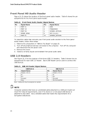
..." on page 25. 2. Turn off all peripheral devices connected to connect two USB devices. Table 9 shows the pin assignments for a full-speed USB device. 46 Intel Desktop Board DP43TF Product Guide Front Panel HD Audio Header Figure 22, D shows the location of the three USB 2.0 headers. Use a shielded cable that meets the requirements for each USB 2.0 header. USB 2.0 Header Signal Names USB Port A Pin Signal Name Pin 1 Power (+5 V) 2 3 D- 4 5 D+ 6 7 Ground 8 9 Key 10 Note: USB ports may be used to the computer. Each USB header can be assigned...
..." on page 25. 2. Turn off all peripheral devices connected to connect two USB devices. Table 9 shows the pin assignments for a full-speed USB device. 46 Intel Desktop Board DP43TF Product Guide Front Panel HD Audio Header Figure 22, D shows the location of the three USB 2.0 headers. Use a shielded cable that meets the requirements for each USB 2.0 header. USB 2.0 Header Signal Names USB Port A Pin Signal Name Pin 1 Power (+5 V) 2 3 D- 4 5 D+ 6 7 Ground 8 9 Key 10 Note: USB ports may be used to the computer. Each USB header can be assigned...
Product Guide
Page 48
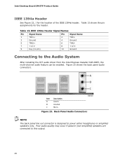
... speakers only. Figure 23 shows the back panel audio connectors. IEEE 1394a Header Signal Names Pin Signal Name 1 TPA1+ 3 Ground 5 TPA2+ 7 +12 V 9 Key (no pin) Pin Signal Name 2 TPA1- 4 Ground 6 TPA2- 8 +12 V 10 Ground Connecting to the Audio System After installing the IDT audio driver from the Intel Express Installer DVD-ROM, the multi-channel audio feature can be enabled. Item Description A Line In B Line Out C Mic In Figure 23. Intel Desktop Board DP43TF Product Guide...
... speakers only. Figure 23 shows the back panel audio connectors. IEEE 1394a Header Signal Names Pin Signal Name 1 TPA1+ 3 Ground 5 TPA2+ 7 +12 V 9 Key (no pin) Pin Signal Name 2 TPA1- 4 Ground 6 TPA2- 8 +12 V 10 Ground Connecting to the Audio System After installing the IDT audio driver from the Intel Express Installer DVD-ROM, the multi-channel audio feature can be enabled. Item Description A Line In B Line Out C Mic In Figure 23. Intel Desktop Board DP43TF Product Guide...
Product Guide
Page 52
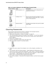
... the computer and the configuration jumper block is installed in the event of a failed BIOS update. Setup displays the maintenance menu again. 9. Configure (2-3) After the Power-On Self-Test (POST) runs, the BIOS displays the Maintenance Menu. Turn off the computer. Remove the computer cover. 4. The computer starts the Setup program. Select Yes and press . Press to select Clear Passwords. Intel Desktop Board DP43TF Product Guide Table 14. Use this menu to boot. 7. Observe the precautions in...
... the computer and the configuration jumper block is installed in the event of a failed BIOS update. Setup displays the maintenance menu again. 9. Configure (2-3) After the Power-On Self-Test (POST) runs, the BIOS displays the Maintenance Menu. Turn off the computer. Remove the computer cover. 4. The computer starts the Setup program. Select Yes and press . Press to select Clear Passwords. Intel Desktop Board DP43TF Product Guide Table 14. Use this menu to boot. 7. Observe the precautions in...

Product Guide
Page 59
... of the Intel® Flash Memory Update Utility and the ease of use of Windows-based installation wizards. Double-click the executable file from the location on your hard drive. (You can also save this file to the Intel Desktop Board DP43TF page. Navigate to a removable USB device. Click on "Latest BIOS" to recover the BIOS if an update fails. To update the BIOS with the Intel® Express BIOS Update Utility With the Intel Express BIOS Update utility you can update the system BIOS while...
... of the Intel® Flash Memory Update Utility and the ease of use of Windows-based installation wizards. Double-click the executable file from the location on your hard drive. (You can also save this file to the Intel Desktop Board DP43TF page. Navigate to a removable USB device. Click on "Latest BIOS" to recover the BIOS if an update fails. To update the BIOS with the Intel® Express BIOS Update Utility With the Intel Express BIOS Update utility you can update the system BIOS while...
Product Guide
Page 62
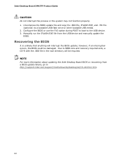
... file from a BIOS update failure, go to BIOS size and recovery requirements, a CD-R with the .BIO file in the root directory will interrupt the BIOS update; NOTE For more information about updating the Intel Desktop Board BIOS or recovering from the USB device and manually update the BIOS. Due to http://support.intel.com/support/motherboards/desktop/sb/CS-022312.htm. 62 Configure the BIOS or use the F10 option during POST to boot to a bootable USB flash drive or other bootable USB media. 2. Uncompress the BIOS update file...
... file from a BIOS update failure, go to BIOS size and recovery requirements, a CD-R with the .BIO file in the root directory will interrupt the BIOS update; NOTE For more information about updating the Intel Desktop Board BIOS or recovering from the USB device and manually update the BIOS. Due to http://support.intel.com/support/motherboards/desktop/sb/CS-022312.htm. 62 Configure the BIOS or use the F10 option during POST to boot to a bootable USB flash drive or other bootable USB media. 2. Uncompress the BIOS update file...


