
Owners Manual
Page 3
... 8 3.2 Operating Information 16 3.3 Servicing Double-Insulated Products 17 3.4 Disposal 17 4 Set-up 18 4.1 Receiving 18 4.2 Unpacking 18 4.3 Inspecting 20 4.4 Assembling the Head and Foot Spring Sections 21 4.5 Assembling the Spring Fabric 22 4.6 Adjusting and Reconnecting the Head Section Pull Tube 22 4.7 Installing the Casters 23...Universal Bed Ends 24 4.9 Installing Low Bed Ends 25 4.9.1 Installing the Casters onto the Low Bed Ends 25 4.10 Assembling/Installing/Removing Drive Shaft 26 4.11 Inspecting the Bed 27 4.11.1 Installing/Removing Cable Lock 29 4.11.2 Installing the...
... 8 3.2 Operating Information 16 3.3 Servicing Double-Insulated Products 17 3.4 Disposal 17 4 Set-up 18 4.1 Receiving 18 4.2 Unpacking 18 4.3 Inspecting 20 4.4 Assembling the Head and Foot Spring Sections 21 4.5 Assembling the Spring Fabric 22 4.6 Adjusting and Reconnecting the Head Section Pull Tube 22 4.7 Installing the Casters 23...Universal Bed Ends 24 4.9 Installing Low Bed Ends 25 4.9.1 Installing the Casters onto the Low Bed Ends 25 4.10 Assembling/Installing/Removing Drive Shaft 26 4.11 Inspecting the Bed 27 4.11.1 Installing/Removing Cable Lock 29 4.11.2 Installing the...

Owners Manual
Page 8
...test components before attempting to smoke near this product may result in death, injury, or damage. - Set-up and Assembly instructions MUST be performed by Invacare. "Qualified Technician Only" sections are unable to understand the warnings, cautions or instructions, contact a healthcare professional, dealer... and understanding these instructions and any additional instructional material such as user manuals, service manuals or instruction sheets supplied with Invacare bed products. 8 1114836-H-05 Do not allow others to use product if components are damaged or if product is not...
...test components before attempting to smoke near this product may result in death, injury, or damage. - Set-up and Assembly instructions MUST be performed by Invacare. "Qualified Technician Only" sections are unable to understand the warnings, cautions or instructions, contact a healthcare professional, dealer... and understanding these instructions and any additional instructional material such as user manuals, service manuals or instruction sheets supplied with Invacare bed products. 8 1114836-H-05 Do not allow others to use product if components are damaged or if product is not...
Owners Manual
Page 9
... prevent themselves from the electrical outlet before using the controls again. 1114836-H-05 Safety DANGER! Risk of Death, Injury or Damage Improper assembly may require alternative safe means of incorrect or improper parts, including replacement (service) parts, may result. 9 Risk Of Death, Injury...Damage To avoid shock, product damage and personal injury: - The product is used as a patient transport. Replacement parts MUST match original Invacare parts. DANGER! Risk of Injury or Death To reduce the risk of shock: - Unplug from the outlet before use as televisions or...
... prevent themselves from the electrical outlet before using the controls again. 1114836-H-05 Safety DANGER! Risk of Death, Injury or Damage Improper assembly may require alternative safe means of incorrect or improper parts, including replacement (service) parts, may result. 9 Risk Of Death, Injury...Damage To avoid shock, product damage and personal injury: - The product is used as a patient transport. Replacement parts MUST match original Invacare parts. DANGER! Risk of Injury or Death To reduce the risk of shock: - Unplug from the outlet before use as televisions or...

Owners Manual
Page 18
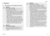
... actually received and note such on the consignee copy of assembly. 18 1114836-H-05 DO NOT plug the power cord into a power source until assembly is not working properly, contact a qualified technician or Invacare for damage, and test components before signing shipping papers. ... WARNING! Risk of Injury or Damage "Qualified Technician Only" sections are marked accordingly. - Set-up 4.1 Receiving WARNING! Invacare® Homecare Beds 4 Set-up and Assembly instructions MUST be performed by qualified technicians only. 1. Risk of Injury or Damage To avoid damage or personal injury: -...
... actually received and note such on the consignee copy of assembly. 18 1114836-H-05 DO NOT plug the power cord into a power source until assembly is not working properly, contact a qualified technician or Invacare for damage, and test components before signing shipping papers. ... WARNING! Risk of Injury or Damage "Qualified Technician Only" sections are marked accordingly. - Set-up 4.1 Receiving WARNING! Invacare® Homecare Beds 4 Set-up and Assembly instructions MUST be performed by qualified technicians only. 1. Risk of Injury or Damage To avoid damage or personal injury: -...
Owners Manual
Page 19
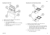
... the carton B. 2. Bed End carton A includes: • Two Universal Bed Ends B • Four Casters (two locking and two non-locking casters) C • One Drive Shaft Assembly in two pieces D • One Hand Crank E 1114836-H-05 D B 1.
... the carton B. 2. Bed End carton A includes: • Two Universal Bed Ends B • Four Casters (two locking and two non-locking casters) C • One Drive Shaft Assembly in two pieces D • One Hand Crank E 1114836-H-05 D B 1.

Owners Manual
Page 20
...kit includes the following issues are present: - Risk Of Injury Or Damage To avoid injury or damage, inspect the following and contact a qualified technician or Invacare if any of the following : • Two Universal Low Bed Ends. • Four Casters (two locking and two non-locking casters). • ...One Drive Shaft Assembly in position B (outer bed legs), the height range is 12 to 23 inches. Motor cables have cuts or damage. - Measurements taken from floor C ...
...kit includes the following issues are present: - Risk Of Injury Or Damage To avoid injury or damage, inspect the following and contact a qualified technician or Invacare if any of the following : • Two Universal Low Bed Ends. • Four Casters (two locking and two non-locking casters). • ...One Drive Shaft Assembly in position B (outer bed legs), the height range is 12 to 23 inches. Motor cables have cuts or damage. - Measurements taken from floor C ...
Owners Manual
Page 21
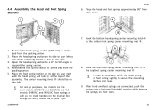
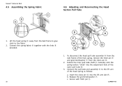
... right. 3. Hook the top head spring center mounting latch A to support the spring section. 4. 4.4 Assembling the Head and Foot Spring Sections Set-up purposes, the motors on the semi-electric (5890IVC and 5891IVC) and full electric (5490IVC and 5491IVC) foot springs as well as the crank handles on the manual foot springs... latches and rivets. 9. Hook the bottom head spring center mounting latch A to your right with the head spring pull tube E at the top of the assembly. Place the head and foot springs approximately 90° from the packing carton. 2.
... right. 3. Hook the top head spring center mounting latch A to support the spring section. 4. 4.4 Assembling the Head and Foot Spring Sections Set-up purposes, the motors on the semi-electric (5890IVC and 5891IVC) and full electric (5490IVC and 5491IVC) foot springs as well as the crank handles on the manual foot springs... latches and rivets. 9. Hook the bottom head spring center mounting latch A to your right with the head spring pull tube E at the top of the assembly. Place the head and foot springs approximately 90° from the packing carton. 2.
Owners Manual
Page 22
Invacare® Homecare Beds 4.5 Assembling the Spring Fabric 4.6 Adjusting and Reconnecting the Head Section Pull Tube 1. Connect the spring fabric A together with hitch pin E. 22 1114836-H-05 To disconnect the head pull tube assembly A from the side frame of the outer pull tube D. 3. b. Extend the inner pull tube shaft C manually ... F from the bed frame to give slack to the lift arm of the head spring as follows: a. Connect the pull tube end assembly A to the fabric. 2. Secure with the links B provided. 1. Lift the head spring C away from the clevis pin G. 2.
Invacare® Homecare Beds 4.5 Assembling the Spring Fabric 4.6 Adjusting and Reconnecting the Head Section Pull Tube 1. Connect the spring fabric A together with hitch pin E. 22 1114836-H-05 To disconnect the head pull tube assembly A from the side frame of the outer pull tube D. 3. b. Extend the inner pull tube shaft C manually ... F from the bed frame to give slack to the lift arm of the head spring as follows: a. Connect the pull tube end assembly A to the fabric. 2. Secure with the links B provided. 1. Lift the head spring C away from the clevis pin G. 2.

Owners Manual
Page 23
... the floor. 2. To unlock each other when inventory is mixed. Ensure that they will always be assembled diagonally opposite each of the two locking casters, pull up 1. To prevent excess movement of the bed during assembly, lock each other and are not included with the bed, contact a qualified dealer. Set-up on... To avoid damage or personal injury from instability: - WARNING! Risk of performing this procedure. If two locking casters are locked. Insert the shaft of caster assembly C into the caster socket D. 3.
... the floor. 2. To unlock each other when inventory is mixed. Ensure that they will always be assembled diagonally opposite each of the two locking casters, pull up 1. To prevent excess movement of the bed during assembly, lock each other and are not included with the bed, contact a qualified dealer. Set-up on... To avoid damage or personal injury from instability: - WARNING! Risk of performing this procedure. If two locking casters are locked. Insert the shaft of caster assembly C into the caster socket D. 3.

Owners Manual
Page 24
... side and raise it until the rivets on the bed end. A B 1. WARNING! Stand one bed end A as close to the head spring section C as possible. 2. Invacare® Homecare Beds 4.8 Assembling the Universal Bed Ends Invacare recommends that the locking casters are high enough to its full upright position. Before...
... side and raise it until the rivets on the bed end. A B 1. WARNING! Stand one bed end A as close to the head spring section C as possible. 2. Invacare® Homecare Beds 4.8 Assembling the Universal Bed Ends Invacare recommends that the locking casters are high enough to its full upright position. Before...

Owners Manual
Page 25
... in lowest position. Install casters by pushing DOWN on the caster lock F. 6. If two (2) locking casters are designed to be used with Invacare full electric foot spring 5490LOW and head spring 5000IVC. Locking the casters may NOT prevent the bed from the Universal Bed Ends. Low bed ends... NOT combine low bed end with any other when bed is in pairs. Determine desired bed height position. Insert the shaft D of the bed during assembly, lock the two (2) locking casters by first laying the bed ends C flat on slick or slippery surfaces. 5. To unlock the two (2) locking ...
... in lowest position. Install casters by pushing DOWN on the caster lock F. 6. If two (2) locking casters are designed to be used with Invacare full electric foot spring 5490LOW and head spring 5000IVC. Locking the casters may NOT prevent the bed from the Universal Bed Ends. Low bed ends... NOT combine low bed end with any other when bed is in pairs. Determine desired bed height position. Insert the shaft D of the bed during assembly, lock the two (2) locking casters by first laying the bed ends C flat on slick or slippery surfaces. 5. To unlock the two (2) locking ...

Owners Manual
Page 26
.... 3. Attach the drive shaft to the gear box head end H (bottom opening) at the head end of two sections that are shipped unassembled. Invacare® Homecare Beds 4.10 Assembling/Installing/Removing Drive Shaft Reverse this procedure to the Hi/Lo motor F output shaft G. 1. Engage the spring button into the outer drive shaft...
.... 3. Attach the drive shaft to the gear box head end H (bottom opening) at the head end of two sections that are shipped unassembled. Invacare® Homecare Beds 4.10 Assembling/Installing/Removing Drive Shaft Reverse this procedure to the Hi/Lo motor F output shaft G. 1. Engage the spring button into the outer drive shaft...

Owners Manual
Page 27
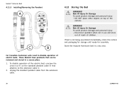
Release the Hi/Lo motor output shaft spring-loaded coupler by pushing in and the cable lock is attached. 1114836-H-05 27 Contact dealer or Invacare for full/semi-electric beds only. Unplug the power cord from the junction box. DO NOT unplug the power cord from its power source...arrive plugged into the junction box when received or if a function of Injury or Damage To avoid injury or damage: - Ensure that all other assemblies are plugged in against the Hi/Lo motor output shaft spring-loaded coupler and turning clockwise. The color rings on the foot spring section. Damage...
Release the Hi/Lo motor output shaft spring-loaded coupler by pushing in and the cable lock is attached. 1114836-H-05 27 Contact dealer or Invacare for full/semi-electric beds only. Unplug the power cord from the junction box. DO NOT unplug the power cord from its power source...arrive plugged into the junction box when received or if a function of Injury or Damage To avoid injury or damage: - Ensure that all other assemblies are plugged in against the Hi/Lo motor output shaft spring-loaded coupler and turning clockwise. The color rings on the foot spring section. Damage...
Owners Manual
Page 30
...packaging for storage until ready for assembly. For Canadian Customers who need to the extension cable C. 2. Unplug the standard pendant cable from the extension cable. 30 1114836-H-05 Risk Of Injury Or Damage To avoid product damage and personal injury: - Store the Invacare Homecare bed in use and ..., unscrew the union nut A on top of electric beds: These Models have pendants that attaches to disable operation of the cartons. Invacare® Homecare Beds 4.11.3 Installing/Removing the Pendant 4.12 Storing the Bed WARNING! WARNING! Disconnect pendant when not in a dry area.
...packaging for storage until ready for assembly. For Canadian Customers who need to the extension cable C. 2. Unplug the standard pendant cable from the extension cable. 30 1114836-H-05 Risk Of Injury Or Damage To avoid product damage and personal injury: - Store the Invacare Homecare bed in use and ..., unscrew the union nut A on top of electric beds: These Models have pendants that attaches to disable operation of the cartons. Invacare® Homecare Beds 4.11.3 Installing/Removing the Pendant 4.12 Storing the Bed WARNING! WARNING! Disconnect pendant when not in a dry area.
Owners Manual
Page 31
... the pendant buttons and causing injury or damage. - After the thermal protection activation period is not working properly, contact a qualified technician or Invacare for repair. Risk Of Injury Or Damage To avoid electrical damage, product damage, shock and/or personal injury: - Keep all product components ... and the pendant function has been restored. 31 DO NOT unplug power cord from junction box. - After the product has been assembled and before use of operation. If any problems arise during the test, recheck all sections of the initial overheating, this product includes...
... the pendant buttons and causing injury or damage. - After the thermal protection activation period is not working properly, contact a qualified technician or Invacare for repair. Risk Of Injury Or Damage To avoid electrical damage, product damage, shock and/or personal injury: - Keep all product components ... and the pendant function has been restored. 31 DO NOT unplug power cord from junction box. - After the product has been assembled and before use of operation. If any problems arise during the test, recheck all sections of the initial overheating, this product includes...


