User Manual
Page 1
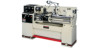
This .pdf document is bookmarked Operation and Maintenance Instructions Geared Head Lathes Models GH-1340W, GH-1440W See manual no. M-321810 Revision G2 11/2014 Copyright © 2014 JET M-321810-1 for service parts and electrical diagrams. JET 427 New Sanford Road LaVergne, Tennessee 37086 Ph.: 800-274-6848 www.jettools.com Part No.
This .pdf document is bookmarked Operation and Maintenance Instructions Geared Head Lathes Models GH-1340W, GH-1440W See manual no. M-321810 Revision G2 11/2014 Copyright © 2014 JET M-321810-1 for service parts and electrical diagrams. JET 427 New Sanford Road LaVergne, Tennessee 37086 Ph.: 800-274-6848 www.jettools.com Part No.
User Manual
Page 2
... of our tools needs service or repair, please contact Technical Service by calling 1-800-274-6846. Warranty Limitations Woodworking products with your area call 1-800-274-6846 or use and are not binding. JET sells through Friday. Hand Tools NOTE: JET is Covered This warranty covers any additional action needed. This warranty does not cover failures due directly or indirectly to provide proof of maintenance. Please...
... of our tools needs service or repair, please contact Technical Service by calling 1-800-274-6846. Warranty Limitations Woodworking products with your area call 1-800-274-6846 or use and are not binding. JET sells through Friday. Hand Tools NOTE: JET is Covered This warranty covers any additional action needed. This warranty does not cover failures due directly or indirectly to provide proof of maintenance. Please...
User Manual
Page 3
... service ...2 2.0 Table of contents...3 3.0 Safety warnings...4 4.0 Specifications ...5 5.0 Uncrating ...6 5.1 Contents of shipping container ...6 6.0 Installation ...7 6.1 Chuck preparation (three jaw) ...7 7.0 Lubrication...8 8.0 Coolant preparation...10 9.0 Electrical connections ...10 10.0 General description ...11 11.0 Operation ...14 11.1 Break-in procedure ...14 11.2 Feed and thread selection...15 11.3 Change gears replacement ...15 11.4 Automatic feed operation and feed changes 15 11.5 Powered carriage travel ...16 11.6 Thread cutting ...16 11.7 Compound...
... service ...2 2.0 Table of contents...3 3.0 Safety warnings...4 4.0 Specifications ...5 5.0 Uncrating ...6 5.1 Contents of shipping container ...6 6.0 Installation ...7 6.1 Chuck preparation (three jaw) ...7 7.0 Lubrication...8 8.0 Coolant preparation...10 9.0 Electrical connections ...10 10.0 General description ...11 11.0 Operation ...14 11.1 Break-in procedure ...14 11.2 Feed and thread selection...15 11.3 Change gears replacement ...15 11.4 Automatic feed operation and feed changes 15 11.5 Powered carriage travel ...16 11.6 Thread cutting ...16 11.7 Compound...

User Manual
Page 4
... warnings may be hazardous. 17. Some examples of a lathe, do a job for maintenance purposes, use by power sanding, sawing, grinding, drilling and other construction activities contain chemicals known to these chemicals, work . Keep belt guard in place and in the OFF position before attempting assembly or operation. 2. Always keep cutters sharp. 24. Don't force a tool or attachment to adjust or remove tools during operation. 23. 3.0 Safety warnings 1.
... warnings may be hazardous. 17. Some examples of a lathe, do a job for maintenance purposes, use by power sanding, sawing, grinding, drilling and other construction activities contain chemicals known to these chemicals, work . Keep belt guard in place and in the OFF position before attempting assembly or operation. 2. Always keep cutters sharp. 24. Don't force a tool or attachment to adjust or remove tools during operation. 23. 3.0 Safety warnings 1.
User Manual
Page 6
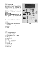
... Blade Screwdriver 4 Open End Wrench (9-11, 10-12, 12-14, 17-19mm) 6 Hex Socket Wrench (2.5, 3, 4, 5, 6, 8mm) 2 Shear Pin 1 30T Change Gear 1 32T Change Gear 2 40T Change Gear 1 Oil Can 2 No. 3 Morse Taper Dead Center 1 No. 5 to your distributor and shipping agent. 5.0 Uncrating Open shipping crate and check for Cam Locks 1 Tool Post Wrench 1 Instruction Manual 1 Parts List Manual 1 Warranty Card Figure 1 6 Missing parts, if any, should be reported to No. 3 Spindle Sleeve 6 Leveling Pads 1 Chuck Key 1 Key...
... Blade Screwdriver 4 Open End Wrench (9-11, 10-12, 12-14, 17-19mm) 6 Hex Socket Wrench (2.5, 3, 4, 5, 6, 8mm) 2 Shear Pin 1 30T Change Gear 1 32T Change Gear 2 40T Change Gear 1 Oil Can 2 No. 3 Morse Taper Dead Center 1 No. 5 to your distributor and shipping agent. 5.0 Uncrating Open shipping crate and check for Cam Locks 1 Tool Post Wrench 1 Instruction Manual 1 Parts List Manual 1 Warranty Card Figure 1 6 Missing parts, if any, should be reported to No. 3 Spindle Sleeve 6 Leveling Pads 1 Chuck Key 1 Key...
User Manual
Page 7
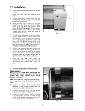
Finish removing the wooden crate from the shipping crate bottom. 3. Cover all gears with a light film of Mobil DTE® Oil Heavy Medium. 7. Clean all components of lathe stand. Support the chuck while turning three camlocks 1/4 turn counter-clockwise with the chuck key enclosed in the lathe base will help you to reach a level condition. Place two steel rods or pipes (of...
Finish removing the wooden crate from the shipping crate bottom. 3. Cover all gears with a light film of Mobil DTE® Oil Heavy Medium. 7. Clean all components of lathe stand. Support the chuck while turning three camlocks 1/4 turn counter-clockwise with the chuck key enclosed in the lathe base will help you to reach a level condition. Place two steel rods or pipes (of...

User Manual
Page 8
... shavings. Oil must be serviced at all lubrication points and all chuck jaws and scroll inside the chuck with an 8mm hex wrench. Tighten in one full turn (if cams turn clockwise. Failure to comply may cause serious damage to the spindle nose and press onto the spindle. Gearbox - To drain, remove drain plug (A, Fig. 6) with a light film of operation. 4. Lift the chuck up...
... shavings. Oil must be serviced at all lubrication points and all chuck jaws and scroll inside the chuck with an 8mm hex wrench. Tighten in one full turn (if cams turn clockwise. Failure to comply may cause serious damage to the spindle nose and press onto the spindle. Gearbox - To drain, remove drain plug (A, Fig. 6) with a light film of operation. 4. Lift the chuck up...
User Manual
Page 10
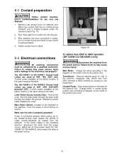
.... The GH-1340W-1 & GH-1440W-1 Geared Head Lathes are rated at 3HP, 1PH, 230V only. Power is cycling properly. 4. Main Motor: Change the wires according to the machine on the inside of the machine, headstock side, switch wire from the tailstock. Change wires in the clockwise direction, disconnect the lathe from the power source. Lathe Power Source Junction Box: Remove the cover. Turns the power to the diagram on and...
.... The GH-1340W-1 & GH-1440W-1 Geared Head Lathes are rated at 3HP, 1PH, 230V only. Power is cycling properly. 4. Main Motor: Change the wires according to the machine on the inside of the machine, headstock side, switch wire from the tailstock. Change wires in the clockwise direction, disconnect the lathe from the power source. Lathe Power Source Junction Box: Remove the cover. Turns the power to the diagram on and...

User Manual
Page 11
... vee slideways, reinforced by four screws with brass shear pins. 11 Figure 11 Figure 12 Figure 13 The hollow spindle has Morse Taper #5 with a Morse Taper #3. The main drive motor is mounted in a dovetail slide and have adjustable gibs. Apron The apron (E, Fig. 12) is mounted to use of two clamping screws when installing a cutting tool. The half nut gibs can be mounted simultaneously. It is bolted...
... vee slideways, reinforced by four screws with brass shear pins. 11 Figure 11 Figure 12 Figure 13 The hollow spindle has Morse Taper #5 with a Morse Taper #3. The main drive motor is mounted in a dovetail slide and have adjustable gibs. Apron The apron (E, Fig. 12) is mounted to use of two clamping screws when installing a cutting tool. The half nut gibs can be mounted simultaneously. It is bolted...
User Manual
Page 12
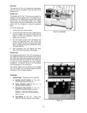
.... A. Power Indicator Light (B, Fig. 14) - Emergency Stop Switch (C, Fig. 14) - Secure the steady rest in position. 3. The sliding fingers are required as a support for tuning operations on the bedway and secured from high quality cast iron and is mounted on long, slender workpieces. The steady rest is mounted to the workpiece and secure by the turning tool. Loosen three hex socket screws...
.... A. Power Indicator Light (B, Fig. 14) - Emergency Stop Switch (C, Fig. 14) - Secure the steady rest in position. 3. The sliding fingers are required as a support for tuning operations on the bedway and secured from high quality cast iron and is mounted on long, slender workpieces. The steady rest is mounted to the workpiece and secure by the turning tool. Loosen three hex socket screws...

User Manual
Page 13
... automatic feeds or damage to speed chart for feeding and threading. 8. Feed/Lead Selector Knob (J, Fig. 14) - lock handle located on front of carriage. Turn clockwise to unlock. located on the front of headstock. Move levers according to lathe may occur. 10. Used for setting up for desired setting. 3. Carriage Lock (B, Fig. 15) - Rotate the wheel counter-clockwise to the left...
... automatic feeds or damage to speed chart for feeding and threading. 8. Feed/Lead Selector Knob (J, Fig. 14) - lock handle located on front of carriage. Turn clockwise to unlock. located on the front of headstock. Move levers according to lathe may occur. 10. Used for setting up for desired setting. 3. Carriage Lock (B, Fig. 15) - Rotate the wheel counter-clockwise to the left...

User Manual
Page 14
... stand pedestals. Tighten screws to off sets the tailstock. 20. located on the electrical box door on the tailstock base are used to hold in the low R.P.M. for cutting tapers. Tailstock Quill Clamping Lever (A, Fig. 16) - Tailstock Clamping Lever (B, Fig. 16) - Push down to the lathe on top of the apron. Rotate clockwise to retract the quill. 19. Turns main power to engage...
... stand pedestals. Tighten screws to off sets the tailstock. 20. located on the electrical box door on the tailstock base are used to hold in the low R.P.M. for cutting tapers. Tailstock Quill Clamping Lever (A, Fig. 16) - Tailstock Clamping Lever (B, Fig. 16) - Push down to the lathe on top of the apron. Rotate clockwise to retract the quill. 19. Turns main power to engage...
User Manual
Page 15
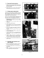
... chart. 11.3 Change gears replacement The 25T, 127T, 50T gears are used with a hex socket cap screw. 7. Close the door and connect the machine to desired rate. 3. Reference the feed and thread found in the tool box are installed in the end gear compartment when delivered from the power source (unplug). 2. Move quadrant (C, Fig. 19) out of this manual). 2. Set selector levers (A, B, C, & D, Fig...
... chart. 11.3 Change gears replacement The 25T, 127T, 50T gears are used with a hex socket cap screw. 7. Close the door and connect the machine to desired rate. 3. Reference the feed and thread found in the tool box are installed in the end gear compartment when delivered from the power source (unplug). 2. Move quadrant (C, Fig. 19) out of this manual). 2. Set selector levers (A, B, C, & D, Fig...

User Manual
Page 18
... is not level, correct to support the other . From steel bar stock of bar stock into chuck and tighten chuck. some drag should not require adjustment. Remove six hex socket cap screws (B, Fig. 26) with a hex key wrench. 4. Remove nuts from the taper pins. 4. Install six socket head cap screws and tighten securely. 18 Figure 25 Figure 26 Set up and cut until the bar stock measurements are...
... is not level, correct to support the other . From steel bar stock of bar stock into chuck and tighten chuck. some drag should not require adjustment. Remove six hex socket cap screws (B, Fig. 26) with a hex key wrench. 4. Remove nuts from the taper pins. 4. Install six socket head cap screws and tighten securely. 18 Figure 25 Figure 26 Set up and cut until the bar stock measurements are...
User Manual
Page 21
M-321810 for operation and maintenance instructions. JET 427 New Sanford Road LaVergne, Tennessee 37086 Ph.: 800-274-6848 www.jettools.com Part No. M-321810-1 Revision H 11/2014 Copyright © 2014 JET This .pdf document is bookmarked Parts List and Electrical Diagrams Geared Head Lathes Models GH-1340W, GH-1440W See manual no.
M-321810 for operation and maintenance instructions. JET 427 New Sanford Road LaVergne, Tennessee 37086 Ph.: 800-274-6848 www.jettools.com Part No. M-321810-1 Revision H 11/2014 Copyright © 2014 JET This .pdf document is bookmarked Parts List and Electrical Diagrams Geared Head Lathes Models GH-1340W, GH-1440W See manual no.
User Manual
Page 22
... and Work Light Assembly - Parts List ...42 2.20.3 W Series Lathes Electrical Schematic Symbol Glossary 43 3.1.1 Wiring Diagram - 1 Phase ...44 3.1.2 Wiring Diagram - 3 Phase ...45 2.0 Replacement Parts To order parts or reach our service department, call will allow us to serve you call 1-800-274-6848, Monday through Friday (see our website for business hours, www.jettools.com). Parts List ...9 2.4.1 Gearbox Assembly I - Having the Model Number and Serial Number of Contents ...2 2.0 Replacement Parts...2 2.1.1 Headstock Assembly I - 1.0 Table of Contents 1.0 Table...
... and Work Light Assembly - Parts List ...42 2.20.3 W Series Lathes Electrical Schematic Symbol Glossary 43 3.1.1 Wiring Diagram - 1 Phase ...44 3.1.2 Wiring Diagram - 3 Phase ...45 2.0 Replacement Parts To order parts or reach our service department, call will allow us to serve you call 1-800-274-6848, Monday through Friday (see our website for business hours, www.jettools.com). Parts List ...9 2.4.1 Gearbox Assembly I - Having the Model Number and Serial Number of Contents ...2 2.0 Replacement Parts...2 2.1.1 Headstock Assembly I - 1.0 Table of Contents 1.0 Table...

User Manual
Page 39
...15 Cluster Gear 50T/20T 1 51 TS-1524011 Set Screw M8x8 1 52 GH1440W-06-14 Spring...1 53 GB308-SB6 Steel Ball 6 1 54 GH1440W-06-13 Shaft...1 55 06-06 Shaft...1 56 GB879-5X30 Pin 5x30 1 57 06-08 Gear 50T ...Wheel...1 69 TS-1523071 Set Screw M6x25 1 70 06-30 Wheel Stud 1 71 GH1440W-06-11 Handle Sleeve 1 72 GH1440W-06-10 Handle Lever 1 73 TS-1522031 Set Screw M5x10 2 74 GB3452.1-25.8X3.55 ....... Part No. O-Ring 25.8x3.55 1 76 TS-1531012 Pan Head Screw M3x6 10 78 GH1440W-06-38 Indicator Label 1 19 Parts List Index No. 2.8.2 Apron Assembly...
...15 Cluster Gear 50T/20T 1 51 TS-1524011 Set Screw M8x8 1 52 GH1440W-06-14 Spring...1 53 GB308-SB6 Steel Ball 6 1 54 GH1440W-06-13 Shaft...1 55 06-06 Shaft...1 56 GB879-5X30 Pin 5x30 1 57 06-08 Gear 50T ...Wheel...1 69 TS-1523071 Set Screw M6x25 1 70 06-30 Wheel Stud 1 71 GH1440W-06-11 Handle Sleeve 1 72 GH1440W-06-10 Handle Lever 1 73 TS-1522031 Set Screw M5x10 2 74 GB3452.1-25.8X3.55 ....... Part No. O-Ring 25.8x3.55 1 76 TS-1531012 Pan Head Screw M3x6 10 78 GH1440W-06-38 Indicator Label 1 19 Parts List Index No. 2.8.2 Apron Assembly...

User Manual
Page 44
... Compound Slide Assembly - Parts List Index No. Knob...1 6 GH1440W-07-19 Spacer...1 7 07-34 Tool Post Pin 1 8 07-29 Tool Post Pin 1 9 GB2089-1X8X11 Spring 1x8x11 1 10 07-37 Clamp Nut 1 11 GB1155-89 Oiler 8 1 12 07-49 Compound Slide 1 13 TS-1503051 Hex Socket Cap Screw M6x20 1 14 07-09 Position Pin 1 15 07-39 Nut ...1 16 07-40 Compound Screw 1 17 GB1096-4X14 Key 4x14 1 18 TS-1531012 Pan Head...
... Compound Slide Assembly - Parts List Index No. Knob...1 6 GH1440W-07-19 Spacer...1 7 07-34 Tool Post Pin 1 8 07-29 Tool Post Pin 1 9 GB2089-1X8X11 Spring 1x8x11 1 10 07-37 Clamp Nut 1 11 GB1155-89 Oiler 8 1 12 07-49 Compound Slide 1 13 TS-1503051 Hex Socket Cap Screw M6x20 1 14 07-09 Position Pin 1 15 07-39 Nut ...1 16 07-40 Compound Screw 1 17 GB1096-4X14 Key 4x14 1 18 TS-1531012 Pan Head...

User Manual
Page 46
...Spring 0.7x5x12 1 17 GH1440W-08-09 Wheel...1 18 TS-1523071 Set Screw M6x25 1 19 08-12 Wheel Screw 1 20 GH1440W-06-10 Handle Lever 1 21 GH1440W-06-11 Handle Sleeve 1 22 GH1440W-T22 Hex Socket Cap Screw M8x70 2 23 GH1440W-08-03 Gib ...1 24 08-18 Gib Adjusting Screw...Base (for 13 1 30 08-02 Stop Pin 1 31 TS-1540041 Nut M6 1 32 TS-1523051 Set Screw M6x16 1 33 GB879-5X12 Pin 5x12 1 34 GH1440W-08-05 Eccentric Shaft 1 35 GH1440W-08-08 Lever Handle 1 36 08-04 Spindle ...1 37 08-24 Key 3x6x55 1 38 08-07 Indicator Label 1 39 GHW-TA39 Pan Head Screw...
...Spring 0.7x5x12 1 17 GH1440W-08-09 Wheel...1 18 TS-1523071 Set Screw M6x25 1 19 08-12 Wheel Screw 1 20 GH1440W-06-10 Handle Lever 1 21 GH1440W-06-11 Handle Sleeve 1 22 GH1440W-T22 Hex Socket Cap Screw M8x70 2 23 GH1440W-08-03 Gib ...1 24 08-18 Gib Adjusting Screw...Base (for 13 1 30 08-02 Stop Pin 1 31 TS-1540041 Nut M6 1 32 TS-1523051 Set Screw M6x16 1 33 GB879-5X12 Pin 5x12 1 34 GH1440W-08-05 Eccentric Shaft 1 35 GH1440W-08-08 Lever Handle 1 36 08-04 Spindle ...1 37 08-24 Key 3x6x55 1 38 08-07 Indicator Label 1 39 GHW-TA39 Pan Head Screw...

User Manual
Page 53
... 1 30 GB879-4X24 Pin 4x24 1 31 GB4141.29A-85 Knob...1 32 GH1440W-01-16 Change Gear Cover (for 14 1 GH1340W-01-16 Change Gear Cover (for 13 1 33 GH1440W-01-18 Rear Plate (for 14 1 GH1340W-01-18 Rear Plate (for 13 1 34 C6240-10004 Plate...2 35 TS-1503021 Hex Socket Cap Screw M6x10 4 33 2.14.2 End Gear Assembly - Part No. Parts List Index No.
... 1 30 GB879-4X24 Pin 4x24 1 31 GB4141.29A-85 Knob...1 32 GH1440W-01-16 Change Gear Cover (for 14 1 GH1340W-01-16 Change Gear Cover (for 13 1 33 GH1440W-01-18 Rear Plate (for 14 1 GH1340W-01-18 Rear Plate (for 13 1 34 C6240-10004 Plate...2 35 TS-1503021 Hex Socket Cap Screw M6x10 4 33 2.14.2 End Gear Assembly - Part No. Parts List Index No.


