
User Manual
Page 1
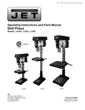
M-354400 Revision B3 11/2014 Copyright © 2014 JET This .pdf document is bookmarked Operating Instructions and Parts Manual Drill Press Models: J-2500, J-2530, J-2550 J-2530 JET 427 New Sanford Road LaVergne, Tennessee 37086 Ph.: 800-274-6848 www.jettools.com J-2500 J-2550 Part No.
M-354400 Revision B3 11/2014 Copyright © 2014 JET This .pdf document is bookmarked Operating Instructions and Parts Manual Drill Press Models: J-2500, J-2530, J-2550 J-2530 JET 427 New Sanford Road LaVergne, Tennessee 37086 Ph.: 800-274-6848 www.jettools.com J-2500 J-2550 Part No.
User Manual
Page 2
... NOT APPLY TO YOU. JET sells through Friday. Machine Accessories; Pro-Duty Air Tools 2 Year - Warehouse & Dock products; Please contact Technical Service at any reason whatsoever. Hand Tools NOTE: JET is designed to -date product information, check with any of maintenance. This warranty does not cover failures due directly or indirectly to the JET brand. 2 Parts; Consumable items; Shop Tools; References in this document...
... NOT APPLY TO YOU. JET sells through Friday. Machine Accessories; Pro-Duty Air Tools 2 Year - Warehouse & Dock products; Please contact Technical Service at any reason whatsoever. Hand Tools NOTE: JET is designed to -date product information, check with any of maintenance. This warranty does not cover failures due directly or indirectly to the JET brand. 2 Parts; Consumable items; Shop Tools; References in this document...
User Manual
Page 3
... Installation ...9 Head Assembly ...9 Chuck and Arbor Installation...9 Chuck and Arbor Removal...10 Adjustment ...10 Depth Stop Adjustment...10 Changing Spindle Speeds ...11 Return Spring Adjustment...11 Work Light (J-2500 and J-2530 only) ...11 Table Tilt Adjustment...12 Operation...12 Installing Drills...12 Positioning the Workpiece ...12 Using the Vise ...12 Basic Operation...12 Maintenance ...12 Lubrication...12 Electrical...13 Grounding Instructions ...13 115 Volt Operation ...13 230 Volt Operation ...13 Extension Cords...13 Troubleshooting ...14 Replacement Parts...15 Parts List - J-2550...
... Installation ...9 Head Assembly ...9 Chuck and Arbor Installation...9 Chuck and Arbor Removal...10 Adjustment ...10 Depth Stop Adjustment...10 Changing Spindle Speeds ...11 Return Spring Adjustment...11 Work Light (J-2500 and J-2530 only) ...11 Table Tilt Adjustment...12 Operation...12 Installing Drills...12 Positioning the Workpiece ...12 Using the Vise ...12 Basic Operation...12 Maintenance ...12 Lubrication...12 Electrical...13 Grounding Instructions ...13 115 Volt Operation ...13 230 Volt Operation ...13 Extension Cords...13 Troubleshooting ...14 Replacement Parts...15 Parts List - J-2550...
User Manual
Page 4
.... 5. Remove all of the machine, a guard or other conditions that use until proper training and knowledge have impact resistant lenses; Keep children away. 21. Read and understand the entire owner's manual before use extreme caution and replace the guards immediately. 16. Read and understand the warnings posted on . 15. Do not operate this type of parts, mounting and any real or implied warranty and...
.... 5. Remove all of the machine, a guard or other conditions that use until proper training and knowledge have impact resistant lenses; Keep children away. 21. Read and understand the entire owner's manual before use extreme caution and replace the guards immediately. 16. Read and understand the warnings posted on . 15. Do not operate this type of parts, mounting and any real or implied warranty and...
User Manual
Page 5
...tool or attachment to perform any machine operation. 24. Never use your work piece. 28. Use a brush or compressed air to a complete stop. 31. Do not stand on a conversation and "horse-play" are careless acts that you do not use your hand to the table. Keep drill bits sharp and clean for lubricating and changing accessories... - - Turn the power off the machine before starting the machine. Maintain tools with the following safety notices used in this manual: This means that if precautions are not heeded, it may be hazardous. 26. Follow instructions for the best...
...tool or attachment to perform any machine operation. 24. Never use your work piece. 28. Use a brush or compressed air to a complete stop. 31. Do not stand on a conversation and "horse-play" are careless acts that you do not use your hand to the table. Keep drill bits sharp and clean for lubricating and changing accessories... - - Turn the power off the machine before starting the machine. Maintain tools with the following safety notices used in this manual: This means that if precautions are not heeded, it may be hazardous. 26. Follow instructions for the best...
User Manual
Page 6
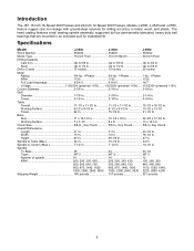
.... Introduction The JET 15-Inch 16-Speed Drill Presses and 20-Inch 12-Speed Drill Presses, Models J-2500, J-2530 and J-2550, feature rugged cast iron design with ground-steel columns for extended life. Base Size 11 x 19-1/2 In 10-1/2 x 18 In 22-3/4 x 17-3/4 In. Spindle to 3/4 In. Specifications Model J-2500 J-2530 J-2550 Stock Number 354400 354401 354402 Model Type 15-Inch Floor 15-Inch Bench 20-Inch Floor Drilling Capacity Cast Iron...
.... Introduction The JET 15-Inch 16-Speed Drill Presses and 20-Inch 12-Speed Drill Presses, Models J-2500, J-2530 and J-2550, feature rugged cast iron design with ground-steel columns for extended life. Base Size 11 x 19-1/2 In 10-1/2 x 18 In 22-3/4 x 17-3/4 In. Spindle to 3/4 In. Specifications Model J-2500 J-2530 J-2550 Stock Number 354400 354401 354402 Model Type 15-Inch Floor 15-Inch Bench 20-Inch Floor Drilling Capacity Cast Iron...
User Manual
Page 7
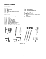
... carton and verify that all parts listed below are included. Main Parts 1 ea 1 ea 1 set 1 ea Head Assembly Table Column and Table Bracket Assembly Base Additional Parts 1. 1 set 2. 1 pc 3. 1 pc 4. 1 pc 5. 1 pc 6. 1 pc 7. 3 pcs 8. 4 pcs 9. 1 set Chuck and Chuck Key Arbor Drift Key Table Crank Handle Table Lock Handle Column Lock Handle Downfeed Handles and Knobs M10 x 40 Hex Cap Screws Hex Wrenches (3mm, 5mm, 6mm) Other Material 1 ea Owner's Manual 1 ea Warranty Registration Card Required Tools 1. 17mm Box Wrench or a 6" - 8" Adjustable Wrench 2. 15/16" wrench Additional Parts 7
... carton and verify that all parts listed below are included. Main Parts 1 ea 1 ea 1 set 1 ea Head Assembly Table Column and Table Bracket Assembly Base Additional Parts 1. 1 set 2. 1 pc 3. 1 pc 4. 1 pc 5. 1 pc 6. 1 pc 7. 3 pcs 8. 4 pcs 9. 1 set Chuck and Chuck Key Arbor Drift Key Table Crank Handle Table Lock Handle Column Lock Handle Downfeed Handles and Knobs M10 x 40 Hex Cap Screws Hex Wrenches (3mm, 5mm, 6mm) Other Material 1 ea Owner's Manual 1 ea Warranty Registration Card Required Tools 1. 17mm Box Wrench or a 6" - 8" Adjustable Wrench 2. 15/16" wrench Additional Parts 7

User Manual
Page 8
... in Figure 3 and tighten firmly. Remove the wrap and take the rack ring (D) and rack (B) off the column (C). 8 Figure 4 Install the table bracket (A) together with kerosene or a light solvent. Install the table lock handle (C), but do not tighten. Using a 17mm wrench, secure the column (B) with the holes in Figure 1 is the same. 4. Figure 3 Crank Handle and Table Lock Handle Referring to Figure 1: 1. Column Assembly Referring to Figure...
... in Figure 3 and tighten firmly. Remove the wrap and take the rack ring (D) and rack (B) off the column (C). 8 Figure 4 Install the table bracket (A) together with kerosene or a light solvent. Install the table lock handle (C), but do not tighten. Using a 17mm wrench, secure the column (B) with the holes in Figure 1 is the same. 4. Figure 3 Crank Handle and Table Lock Handle Referring to Figure 1: 1. Column Assembly Referring to Figure...

User Manual
Page 9
... are snug. Chuck and Arbor Installation Referring to Figure 6: 1. Push chuck (B) by hand onto the arbor (A), and slide assembly firmly up into position Do not use a steel hammer directly against the bottom of a second person, carefully lift the head onto the column top and slide it down into the spindle (C). 4. The head assembly is heavy! Tighten two setscrews (A) with the sides of the base. 9 Figure 8 Figure 7 4. Tighten the table lock handle (C). Any...
... are snug. Chuck and Arbor Installation Referring to Figure 6: 1. Push chuck (B) by hand onto the arbor (A), and slide assembly firmly up into position Do not use a steel hammer directly against the bottom of a second person, carefully lift the head onto the column top and slide it down into the spindle (C). 4. The head assembly is heavy! Tighten two setscrews (A) with the sides of the base. 9 Figure 8 Figure 7 4. Tighten the table lock handle (C). Any...

User Manual
Page 10
... 9: 1. Chuck and Arbor Removal Referring to your other hand, advance the lock nuts (B) on the table, and lower quill (A) using the downfeed handle. 4. Insert the drift key (B) into the workpiece. 2. With the drill bit in the quill. 5. Adjustment Depth Stop Adjustment Referring to this point. 5. Figure 9 Figure 10 10 The drill bit will drill into the aligned slots and tap lightly. The chuck and arbor assembly should fall from the power source. 2. To release, advance the nuts...
... 9: 1. Chuck and Arbor Removal Referring to your other hand, advance the lock nuts (B) on the table, and lower quill (A) using the downfeed handle. 4. Insert the drift key (B) into the workpiece. 2. With the drill bit in the quill. 5. Adjustment Depth Stop Adjustment Referring to this point. 5. Figure 9 Figure 10 10 The drill bit will drill into the aligned slots and tap lightly. The chuck and arbor assembly should fall from the power source. 2. To release, advance the nuts...

User Manual
Page 11
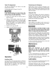
...-clockwise to this chart whenever changing speeds. Install a light bulb, no larger than 60 watts into the socket accessed from the power source. 2. Changing Spindle Speeds A spindle speed and pulley/belt arrangement chart for J-2500, J-2530 Return Spring Adjustment The return spring is adjusted at the factory and should not need further adjustment. Tighten two bar knobs (E, Fig. 11). Do not over-tighten. Nuts should be tightened against each side of the...
...-clockwise to this chart whenever changing speeds. Install a light bulb, no larger than 60 watts into the socket accessed from the power source. 2. Changing Spindle Speeds A spindle speed and pulley/belt arrangement chart for J-2500, J-2530 Return Spring Adjustment The return spring is adjusted at the factory and should not need further adjustment. Tighten two bar knobs (E, Fig. 11). Do not over-tighten. Nuts should be tightened against each side of the...
User Manual
Page 12
...! If the power cord is worn, cut, or damaged in degrees) displayed on the scale (D, Fig 15) at slower speeds. All of the ball bearings are made on the table. Loosen the socket head set screw (A). Tighten the socket head set screw (A) with the column, use a backup piece of scrap wood to comply may cause the motor to stop and/or the drill bit to the table. Figure 14...
...! If the power cord is worn, cut, or damaged in degrees) displayed on the scale (D, Fig 15) at slower speeds. All of the ball bearings are made on the table. Loosen the socket head set screw (A). Tighten the socket head set screw (A) with the column, use a backup piece of scrap wood to comply may cause the motor to stop and/or the drill bit to the table. Figure 14...
User Manual
Page 13
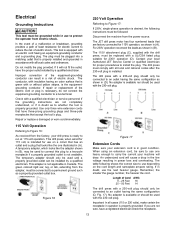
... 230-volt plug. 115 Volt Operation Referring to Figure 16: As received from the power source. Improper connection of electric shock. If repair or replacement of Cord AWG 000 - 25 Feet 16 025 - 50 Feet 14 The drill press with a 230-volt plug should only be used with all local codes and ordinances. Check with a qualified electrician or service personnel if the grounding instructions...
... 230-volt plug. 115 Volt Operation Referring to Figure 16: As received from the power source. Improper connection of electric shock. If repair or replacement of Cord AWG 000 - 25 Feet 16 025 - 50 Feet 14 The drill press with a 230-volt plug should only be used with all local codes and ordinances. Check with a qualified electrician or service personnel if the grounding instructions...
User Manual
Page 14
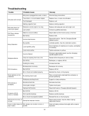
... Changing Spindle Speeds section. Tighten setscrews in workpiece. Resharpen, or replace drill bit. Replace drill bit. Tighten chuck jaws. Replace spindle bearings. Reinstall the bit, or chuck properly. See the Return Spring Adjustment section. Extension cord too light or too long. Bad belt(s). Workpiece Burns. Dull drill bit. No backing board used. Worn spindle bearings. Spring has improper tension. Replace cord. Replace with a cleaner degreaser. 14 Support or clamp workpiece. Incorrect belt tension. Feeding too slowly. Bit, or chuck not installed...
... Changing Spindle Speeds section. Tighten setscrews in workpiece. Resharpen, or replace drill bit. Replace drill bit. Tighten chuck jaws. Replace spindle bearings. Reinstall the bit, or chuck properly. See the Return Spring Adjustment section. Extension cord too light or too long. Bad belt(s). Workpiece Burns. Dull drill bit. No backing board used. Worn spindle bearings. Spring has improper tension. Replace cord. Replace with a cleaner degreaser. 14 Support or clamp workpiece. Incorrect belt tension. Feeding too slowly. Bit, or chuck not installed...
User Manual
Page 15
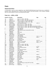
... Hex Socket Set Screw M10-12 2 27 JDP15-1027 Lamp Socket 1 28 TS-1534042 Cr. Re. Spring Washer 1/2 1 36 TS-1540081 Hex Nut M12 2 37 10603704 Hub ...1 38 10603807 Feed Shaft 1 JDP15-1038 Feed Shaft Assy (includes #37 thru #39 1 39 JDP12-55 Roll Pin M5x16 1 43A...........JDP15-1043 Handle Bar 1 15 Having the Model Number and Serial Number of your...
... Hex Socket Set Screw M10-12 2 27 JDP15-1027 Lamp Socket 1 28 TS-1534042 Cr. Re. Spring Washer 1/2 1 36 TS-1540081 Hex Nut M12 2 37 10603704 Hub ...1 38 10603807 Feed Shaft 1 JDP15-1038 Feed Shaft Assy (includes #37 thru #39 1 39 JDP12-55 Roll Pin M5x16 1 43A...........JDP15-1043 Handle Bar 1 15 Having the Model Number and Serial Number of your...
User Manual
Page 16
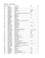
... Pulley Set Nut 1 70 JDP15-1070 Spindle Pulley 1 71 21015M2J30 Drilling Arbor MT2*JT3 1 72A...........JDP15-1072 Chuck Assy 1 73 10607303 Wedge Shifter 1 74 JDP15-1074 Motor ...1 JDP15-1074A.......... Re. Parallel Key 5 x 5-20 1 81 TS-1504021 Hex Socket Set Screw M8-12 1 83 JDP15-1083 Strain Relief 1 84 TS-1534042 Cr. Pan Head Screw M5-8 3 112 ...........10611201 Chuck Key Holder 1 113 ...........TS-2286122 Cr. Round Washer...
... Pulley Set Nut 1 70 JDP15-1070 Spindle Pulley 1 71 21015M2J30 Drilling Arbor MT2*JT3 1 72A...........JDP15-1072 Chuck Assy 1 73 10607303 Wedge Shifter 1 74 JDP15-1074 Motor ...1 JDP15-1074A.......... Re. Parallel Key 5 x 5-20 1 81 TS-1504021 Hex Socket Set Screw M8-12 1 83 JDP15-1083 Strain Relief 1 84 TS-1534042 Cr. Pan Head Screw M5-8 3 112 ...........10611201 Chuck Key Holder 1 113 ...........TS-2286122 Cr. Round Washer...

User Manual
Page 17
... 1 801 ...........JDP15-1801 Lead Wire Assembly 1 848 ...........JDP15-1848 Drive Screw 2.3-5 2 849 ...........JDP15-1849 Scale ...1 922 ...........2801ABRF04 .......... Strain Relief 20 2 999 ...........TS-1540081 Hex Nut M12x10 3 1000 .........100633Y8 Plastic Sleeve 1 1001 .........10810401A1 Chuck Guard Assembly 1 17 J-2500, J-2530 Index No. Roll Pin 6-25 2 162 ...........10916202 Warning Label 1 166 ...........JDP15-1166 Speed Diagram 1 169 JDP15-1169 Trade-Mark Label 1 170 ...........2658MZDU36.......... Re. Parts List -
... 1 801 ...........JDP15-1801 Lead Wire Assembly 1 848 ...........JDP15-1848 Drive Screw 2.3-5 2 849 ...........JDP15-1849 Scale ...1 922 ...........2801ABRF04 .......... Strain Relief 20 2 999 ...........TS-1540081 Hex Nut M12x10 3 1000 .........100633Y8 Plastic Sleeve 1 1001 .........10810401A1 Chuck Guard Assembly 1 17 J-2500, J-2530 Index No. Roll Pin 6-25 2 162 ...........10916202 Warning Label 1 166 ...........JDP15-1166 Speed Diagram 1 169 JDP15-1169 Trade-Mark Label 1 170 ...........2658MZDU36.......... Re. Parts List -
User Manual
Page 19
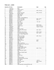
..., Motor Base 1 33 5627931 Lock, Motor Bar 2 34 J-5627941 Base, Motor 1 35 5627181 Washer, Spring 1/2 2 36 5627191 Nut, Hex M12 2 37 5627211 Hub ...1 38 5627951 Shaft, Feed Pinion 1 38A...........5627961 Shaft Assembly, Feed Pinion 1 39 5627971 Pin, Roll 1 40 5627241 Pin, Scale Set 1 41 5627981 Wedge, Scale Locking 1 42 5627991 Screw, Depth Lock M8 x 17 mm 1 43 5629011 Handle 3 43A...........5629021 Bar Assembly, Handle 3 44 5627271 Grip ...3 45 5629031 Housing, Spindle Depth...
..., Motor Base 1 33 5627931 Lock, Motor Bar 2 34 J-5627941 Base, Motor 1 35 5627181 Washer, Spring 1/2 2 36 5627191 Nut, Hex M12 2 37 5627211 Hub ...1 38 5627951 Shaft, Feed Pinion 1 38A...........5627961 Shaft Assembly, Feed Pinion 1 39 5627971 Pin, Roll 1 40 5627241 Pin, Scale Set 1 41 5627981 Wedge, Scale Locking 1 42 5627991 Screw, Depth Lock M8 x 17 mm 1 43 5629011 Handle 3 43A...........5629021 Bar Assembly, Handle 3 44 5627271 Grip ...3 45 5629031 Housing, Spindle Depth...
User Manual
Page 20
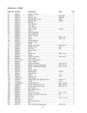
..............5629431 Screw, Socket Head Cap M8 x 25 mm 1 131 ...........5629441 Key, Chuck 1 140 ...........5629451 Shaft, Motor Base 1 149 ...........5629461 Pin, Roll 2 601 ...........5629471 Screw, Pan Head M4 x 12 mm 1 602 ...........5629481 Washer, External Tooth Lock 4 2 605 ...........5629491 Pin, Roll 1 606 ...........5629511 Pin, Roll 2.5 x 10 mm 1 610 ...........5513738 Screw 2 611 ...........5513739 Block, Depth Stop 1 612 ...........5513740 Nut ...1 613 ...........5513741 Rod, Depth Stop Adjustment 2550 Only 1 20 Part No. Parts List - J-2550 Index...
..............5629431 Screw, Socket Head Cap M8 x 25 mm 1 131 ...........5629441 Key, Chuck 1 140 ...........5629451 Shaft, Motor Base 1 149 ...........5629461 Pin, Roll 2 601 ...........5629471 Screw, Pan Head M4 x 12 mm 1 602 ...........5629481 Washer, External Tooth Lock 4 2 605 ...........5629491 Pin, Roll 1 606 ...........5629511 Pin, Roll 2.5 x 10 mm 1 610 ...........5513738 Screw 2 611 ...........5513739 Block, Depth Stop 1 612 ...........5513740 Nut ...1 613 ...........5513741 Rod, Depth Stop Adjustment 2550 Only 1 20 Part No. Parts List - J-2550 Index...
User Manual
Page 21
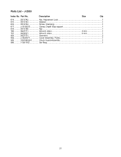
J-2550 Index No. Part No. Parts List - Description Size Qty 614 ...........5513742 Nut, Adjustment Lock 1 615 ...........5513743 Washer 1 616 ...........5513744 Screw, Clamping 1 617 ...........J-5518233 Clamp, Depth Stop support 1 618 ...........5513746 Nut ...1 700 ...........5627711 Wrench, Allen 3 mm 1 701 ...........5629521 Wrench, Allen 5 mm 1 903 ...........5627721 Grommet 2 904 ...........J-5629371 Cover Assembly, Pulley 1 905 ...........10810402A1 Chuck Guard Assembly 1 906 ...........11361702 Set Ring 1 21
J-2550 Index No. Part No. Parts List - Description Size Qty 614 ...........5513742 Nut, Adjustment Lock 1 615 ...........5513743 Washer 1 616 ...........5513744 Screw, Clamping 1 617 ...........J-5518233 Clamp, Depth Stop support 1 618 ...........5513746 Nut ...1 700 ...........5627711 Wrench, Allen 3 mm 1 701 ...........5629521 Wrench, Allen 5 mm 1 903 ...........5627721 Grommet 2 904 ...........J-5629371 Cover Assembly, Pulley 1 905 ...........10810402A1 Chuck Guard Assembly 1 906 ...........11361702 Set Ring 1 21


