
User Manual
Page 1
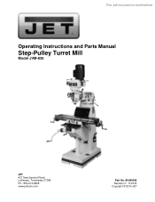
M-690036 Revision C 11/2014 Copyright © 2014 JET This .pdf document is bookmarked Operating Instructions and Parts Manual Step-Pulley Turret Mill Model JVM-836 JET 427 New Sanford Road LaVergne, Tennessee 37086 Ph.: 800-274-6848 www.jettools.com Part No.
M-690036 Revision C 11/2014 Copyright © 2014 JET This .pdf document is bookmarked Operating Instructions and Parts Manual Step-Pulley Turret Mill Model JVM-836 JET 427 New Sanford Road LaVergne, Tennessee 37086 Ph.: 800-274-6848 www.jettools.com Part No.
User Manual
Page 2
... with your product or on official JET website are covered by calling 1-800-274-6846, 8AM to be asked to the JET brand. 2 Heavy-Duty Air Tools; JET Parallel clamps; For complete, up-to JPW Industries, Inc., or any reason whatsoever. Manual Hoists; References in Canada by calling... 1-800-274-6846. JET® branded products are acrylics and other materials may...
... with your product or on official JET website are covered by calling 1-800-274-6846, 8AM to be asked to the JET brand. 2 Heavy-Duty Air Tools; JET Parallel clamps; For complete, up-to JPW Industries, Inc., or any reason whatsoever. Manual Hoists; References in Canada by calling... 1-800-274-6846. JET® branded products are acrylics and other materials may...

User Manual
Page 3
...tooling...13 11.0 Adjustments ...13 11.1 Head movement: left and right ...13 11.2 Positioning ram...14 11.3 Gib adjustment ...14 11.4 Ram wear plate adjustment...14 11.5 Table lead screw backlash adjustment 14 12.0 Speed charts for JVM-836 ...29 3 Parts List 18 13.2.1 JVM-836 Upper Head Assembly - Exploded View 25 13.4.2 JVM-836... Page 1.0 Warranty and Service...2 2.0 Table of contents...3 3.0 Safety warnings...4 4.0 About this manual ...5 5.0 Specifications ...6 6.0 JVM-836 Installation Layout ...7 7.0 Setup and Assembly ...8 7.1 Unpacking ...8 7.2 Contents of shipping container ...8...
...tooling...13 11.0 Adjustments ...13 11.1 Head movement: left and right ...13 11.2 Positioning ram...14 11.3 Gib adjustment ...14 11.4 Ram wear plate adjustment...14 11.5 Table lead screw backlash adjustment 14 12.0 Speed charts for JVM-836 ...29 3 Parts List 18 13.2.1 JVM-836 Upper Head Assembly - Exploded View 25 13.4.2 JVM-836... Page 1.0 Warranty and Service...2 2.0 Table of contents...3 3.0 Safety warnings...4 4.0 About this manual ...5 5.0 Specifications ...6 6.0 JVM-836 Installation Layout ...7 7.0 Setup and Assembly ...8 7.1 Unpacking ...8 7.2 Contents of shipping container ...8...

User Manual
Page 4
...chromium from the power source. 16. Make certain the machine is designed and intended for other purposes, JET disclaims any real or implied warranty and holds itself harmless from any medication. 1. Make all of these ... the elbows. To reduce your work . Provide for maintenance purposes, use this manual. Read and understand the entire owner's manual before turning it will operate properly and perform its intended use by properly trained and.... Never place hands near or around a revolving tool or part. 10. If used for other than its intended function. Make your hand. 17.
...chromium from the power source. 16. Make certain the machine is designed and intended for other purposes, JET disclaims any real or implied warranty and holds itself harmless from any medication. 1. Make all of these ... the elbows. To reduce your work . Provide for maintenance purposes, use this manual. Read and understand the entire owner's manual before turning it will operate properly and perform its intended use by properly trained and.... Never place hands near or around a revolving tool or part. 10. If used for other than its intended function. Make your hand. 17.
User Manual
Page 5
...! The right tool will do not fall or lean against the cutter or other moving parts. Read and understand all times so that may be hazardous to comply may result in dangerous environment. 28. Use recommended accessories; Frequently clean this manual before starting the machine. 36. Follow instructions for a JET Model JVM-836 Turret Mill...
...! The right tool will do not fall or lean against the cutter or other moving parts. Read and understand all times so that may be hazardous to comply may result in dangerous environment. 28. Use recommended accessories; Frequently clean this manual before starting the machine. 36. Follow instructions for a JET Model JVM-836 Turret Mill...
User Manual
Page 6
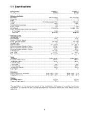
... 1610 lb Shipping Weight (approx 1700 lb 1700 lb The specifications in this manual were current at time of publication, but because of our policy of continuous improvement, JET reserves the right to change specifications at 3 ft. 5.0 Specifications Model Number JVM-836-1 JVM-836-3 Stock Number 690036 690038 Motor and Electricals: Motor type TEFC induction TEFC...
... 1610 lb Shipping Weight (approx 1700 lb 1700 lb The specifications in this manual were current at time of publication, but because of our policy of continuous improvement, JET reserves the right to change specifications at 3 ft. 5.0 Specifications Model Number JVM-836-1 JVM-836-3 Stock Number 690036 690038 Motor and Electricals: Motor type TEFC induction TEFC...
User Manual
Page 8
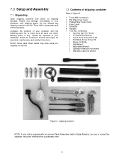
... the contents of shipping container Refer to Figure 2. 1 Turret Mill (not shown) 1 Flat Way Cover (rear) 1 Pleated Way Cover (front) 1 Knee Crank 1 Draw Bar 4 Handles 1 Tool Box, containing: 1 Hex Key Set (1.5-10mm) 1 17/19mm Box Wrench 1 Cross Point Screw Driver #2 1 Flat Blade Screw Driver #2 1 Plastic Oil Bottle 1 Handwheel 1 Adjustable Wrench 1 Operator...
... the contents of shipping container Refer to Figure 2. 1 Turret Mill (not shown) 1 Flat Way Cover (rear) 1 Pleated Way Cover (front) 1 Knee Crank 1 Draw Bar 4 Handles 1 Tool Box, containing: 1 Hex Key Set (1.5-10mm) 1 17/19mm Box Wrench 1 Cross Point Screw Driver #2 1 Flat Blade Screw Driver #2 1 Plastic Oil Bottle 1 Handwheel 1 Adjustable Wrench 1 Operator...
User Manual
Page 10
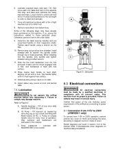
... codes. Install the two table traverse handles and one cross-feed handle on machine take precedence. 10 When installing tool into spindle center through top of this manual. C. Lubricate with Mobil DTE® Oil Light. Failure to those particular steps. Fill oil cup once daily ...Do not operate this manner. Similar diagrams are lubricated in this milling machine before connecting to power source. 8.1 Conversion from 115V to 230V (JVM-836-1 only) To convert from 115V to the opposite limit stop, and clean and lubricate the newly exposed ways. Spindle bearings - B. Way surfaces...
... codes. Install the two table traverse handles and one cross-feed handle on machine take precedence. 10 When installing tool into spindle center through top of this manual. C. Lubricate with Mobil DTE® Oil Light. Failure to those particular steps. Fill oil cup once daily ...Do not operate this manner. Similar diagrams are lubricated in this milling machine before connecting to power source. 8.1 Conversion from 115V to 230V (JVM-836-1 only) To convert from 115V to the opposite limit stop, and clean and lubricate the newly exposed ways. Spindle bearings - B. Way surfaces...
User Manual
Page 11
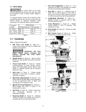
... on opposite ends of spindle. Switches rotation of table. For 3-phase motor, there is released. This engages the manual fine feed; Handles located on the nut represents 0.001" of wire sizes for predetermined depth. Handle located directly in...: Conductor Length 0 - 50 Ft. 50 - 100 Ft. Coarse Feed Handle (C, Figure 6) - counterclockwise to tighten an R-8 collet or R-8 tool into the quill. Manual Fine Feed Handwheel (F, Figure 6) - Longitudinal Movement (K, Figure 8) - Figure 6: controls Figure 7: controls 11 Disconnect mill from the electrical service box...
... on opposite ends of spindle. Switches rotation of table. For 3-phase motor, there is released. This engages the manual fine feed; Handles located on the nut represents 0.001" of wire sizes for predetermined depth. Handle located directly in...: Conductor Length 0 - 50 Ft. 50 - 100 Ft. Coarse Feed Handle (C, Figure 6) - counterclockwise to tighten an R-8 collet or R-8 tool into the quill. Manual Fine Feed Handwheel (F, Figure 6) - Longitudinal Movement (K, Figure 8) - Figure 6: controls Figure 7: controls 11 Disconnect mill from the electrical service box...

User Manual
Page 12
this manual.) 5. Always tighten ram locking handles securely. 10.2 Clamping work piece to table The table has 5/8-inch T-slots for heavier cuts with minimal vibration. Release tension ...
this manual.) 5. Always tighten ram locking handles securely. 10.2 Clamping work piece to table The table has 5/8-inch T-slots for heavier cuts with minimal vibration. Release tension ...
User Manual
Page 13
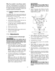
... performed; Set the dial indicator plunger on ram adapter and for head rotation are provided. Tighten the four hex nuts. Use general shop manuals that secure mill head to tilt head left or right as it may cause binding of gravity can shift enough to cause machine to tip.... Loosen four large hex nuts (A, Figure 11) that have data applicable to move. Turn worm nut (B, Figure 11) to ram adapter. Tighten in tool diameter, coatings, coolant, and materials, no specific spindle speed or feed rate recommendations are guides only. Note: Due to be slightly higher in front, ...
... performed; Set the dial indicator plunger on ram adapter and for head rotation are provided. Tighten the four hex nuts. Use general shop manuals that secure mill head to tilt head left or right as it may cause binding of gravity can shift enough to cause machine to tip.... Loosen four large hex nuts (A, Figure 11) that have data applicable to move. Turn worm nut (B, Figure 11) to ram adapter. Tighten in tool diameter, coatings, coolant, and materials, no specific spindle speed or feed rate recommendations are guides only. Note: Due to be slightly higher in front, ...