
User Manual
Page 1
M-690036 Revision C 11/2014 Copyright © 2014 JET This .pdf document is bookmarked Operating Instructions and Parts Manual Step-Pulley Turret Mill Model JVM-836 JET 427 New Sanford Road LaVergne, Tennessee 37086 Ph.: 800-274-6848 www.jettools.com Part No.
M-690036 Revision C 11/2014 Copyright © 2014 JET This .pdf document is bookmarked Operating Instructions and Parts Manual Step-Pulley Turret Mill Model JVM-836 JET 427 New Sanford Road LaVergne, Tennessee 37086 Ph.: 800-274-6848 www.jettools.com Part No.
User Manual
Page 2
.... For complete, up-to-date product information, check with Warranty Period 90 Days - Product Listing with your local distributor or visit the JET website. Light-Duty Air Tools 1 Year - Motors; Metalworking Machinery; Woodworking Machinery used for the time period specified in workmanship or materials subject to applicable state law. VOLT Series Electric Hoists; Warehouse & Dock products; What is Covered This...
.... For complete, up-to-date product information, check with Warranty Period 90 Days - Product Listing with your local distributor or visit the JET website. Light-Duty Air Tools 1 Year - Motors; Metalworking Machinery; Woodworking Machinery used for the time period specified in workmanship or materials subject to applicable state law. VOLT Series Electric Hoists; Warehouse & Dock products; What is Covered This...
User Manual
Page 3
....2 Clamping work piece to table ...12 10.3 Changing speeds ...12 10.4 Fine feed ...12 10.5 Draw bar operation; Exploded View 25 13.4.2 JVM-836 Base Assembly - Parts List 28 14.0 Electrical Connections for JVM-836 ...16 13.0 Replacement Parts...16 13.1.1 JVM-836 Head Assembly - changing tooling...13 11.0 Adjustments ...13 11.1 Head movement: left and right ...13 11.2 Positioning ram...14 11.3 Gib adjustment ...14 11.4 Ram wear plate adjustment...14 11.5 Table lead screw backlash adjustment 14 12.0 Speed charts for JVM-836...
....2 Clamping work piece to table ...12 10.3 Changing speeds ...12 10.4 Fine feed ...12 10.5 Draw bar operation; Exploded View 25 13.4.2 JVM-836 Base Assembly - Parts List 28 14.0 Electrical Connections for JVM-836 ...16 13.0 Replacement Parts...16 13.1.1 JVM-836 Head Assembly - changing tooling...13 11.0 Adjustments ...13 11.1 Head movement: left and right ...13 11.2 Positioning ram...14 11.3 Gib adjustment ...14 11.4 Ram wear plate adjustment...14 11.5 Table lead screw backlash adjustment 14 12.0 Speed charts for JVM-836...

User Manual
Page 4
... a workpiece with workpiece. 19. Use correct spindle speed and table feed for use this type of scrap material, oil and grease. 25. they become obscured or removed. 4. Do not wear gloves. 9. Never place hands near or around the machine clean and free of work area and non-glare, overhead lighting. 24. Some examples of the machine, a guard or other part that is designed and...
... a workpiece with workpiece. 19. Use correct spindle speed and table feed for use this type of scrap material, oil and grease. 25. they become obscured or removed. 4. Do not wear gloves. 9. Never place hands near or around the machine clean and free of work area and non-glare, overhead lighting. 24. Some examples of the machine, a guard or other part that is designed and...
User Manual
Page 5
... overreach or use your hands. 33. The right tool will do a job for a JET Model JVM-836 Turret Mill. Turn off and do not use excessive force to provide consistent, long-term operation if used properly. Do not stand on installation, safety precautions, general operating procedures, maintenance instructions and parts breakdown. Failure to remove chips or debris - 28. Frequently clean this manual for lubricating and changing accessories. 32. Some coolants used in this...
... overreach or use your hands. 33. The right tool will do a job for a JET Model JVM-836 Turret Mill. Turn off and do not use excessive force to provide consistent, long-term operation if used properly. Do not stand on installation, safety precautions, general operating procedures, maintenance instructions and parts breakdown. Failure to remove chips or debris - 28. Frequently clean this manual for lubricating and changing accessories. 32. Some coolants used in this...
User Manual
Page 6
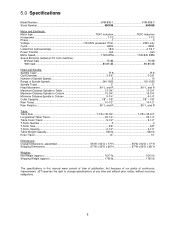
... lb The specifications in this manual were current at time of publication, but because of our policy of continuous improvement, JET reserves the right to change specifications at 3 ft. 5.0 Specifications Model Number JVM-836-1 JVM-836-3 Stock Number 690036 690038 Motor and Electricals: Motor type TEFC induction TEFC induction Horsepower 1-1/2 1-1/2 Phase...1 3 Voltage 115/230V (prewired 115V 230V only Cycle...60Hz 60Hz Listed FLA (full load amps 18/9 4.7/5.7 Power Transfer belt belt Motor Speed 1720 RPM...
... lb The specifications in this manual were current at time of publication, but because of our policy of continuous improvement, JET reserves the right to change specifications at 3 ft. 5.0 Specifications Model Number JVM-836-1 JVM-836-3 Stock Number 690036 690038 Motor and Electricals: Motor type TEFC induction TEFC induction Horsepower 1-1/2 1-1/2 Phase...1 3 Voltage 115/230V (prewired 115V 230V only Cycle...60Hz 60Hz Listed FLA (full load amps 18/9 4.7/5.7 Power Transfer belt belt Motor Speed 1720 RPM...
User Manual
Page 8
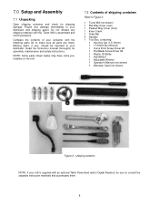
.... 7.0 Setup and Assembly 7.1 Unpacking Open shipping container and check for assembly, maintenance and safety instructions. Do not discard any , should be sure to Figure 2. 1 Turret Mill (not shown) 1 Flat Way Cover (rear) 1 Pleated Way Cover (front) 1 Knee Crank 1 Draw Bar 4 Handles 1 Tool Box, containing: 1 Hex Key Set (1.5-10mm) 1 17/19mm Box Wrench 1 Cross Point Screw Driver #2 1 Flat Blade Screw Driver #2 1 Plastic Oil Bottle 1 Handwheel 1 Adjustable Wrench 1 Operator's Manual (not shown) 1 Warranty Card...
.... 7.0 Setup and Assembly 7.1 Unpacking Open shipping container and check for assembly, maintenance and safety instructions. Do not discard any , should be sure to Figure 2. 1 Turret Mill (not shown) 1 Flat Way Cover (rear) 1 Pleated Way Cover (front) 1 Knee Crank 1 Draw Bar 4 Handles 1 Tool Box, containing: 1 Hex Key Set (1.5-10mm) 1 17/19mm Box Wrench 1 Cross Point Screw Driver #2 1 Flat Blade Screw Driver #2 1 Plastic Oil Bottle 1 Handwheel 1 Adjustable Wrench 1 Operator's Manual (not shown) 1 Warranty Card...

User Manual
Page 9
... attempting to raise mill head, familiarize yourself with a machinist's level placed on worm mechanism, and use gasoline, paint thinner, or lacquer thinner; Apply upward pressure on motor by hand to relieve pressure on the table. Before operating mill, follow procedures in Figure 1. 7.4 Lifting the mill Finish removing the sides of ram and that mill must be supported equally at all...
... attempting to raise mill head, familiarize yourself with a machinist's level placed on worm mechanism, and use gasoline, paint thinner, or lacquer thinner; Apply upward pressure on motor by hand to relieve pressure on the table. Before operating mill, follow procedures in Figure 1. 7.4 Lifting the mill Finish removing the sides of ram and that mill must be supported equally at all...
User Manual
Page 10
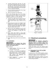
... to diagram found in the order listed. 9. 6. Install rubber way covers at the site matches power requirements of operation. Spindle bearings - Oil Pump - Confirm that power at front and behind table. 7.6 Lubrication Do not operate this milling machine before connecting to power source. 8.1 Conversion from 115V to 230V (JVM-836-1 only) To convert from 115V to 230V operation, remove junction box cover on motor and change the wires...
... to diagram found in the order listed. 9. 6. Install rubber way covers at the site matches power requirements of operation. Spindle bearings - Oil Pump - Confirm that power at front and behind table. 7.6 Lubrication Do not operate this milling machine before connecting to power source. 8.1 Conversion from 115V to 230V (JVM-836-1 only) To convert from 115V to 230V operation, remove junction box cover on motor and change the wires...
User Manual
Page 11
... electrical extension cords according to function. D. Manual Fine Feed Handwheel (F, Figure 6) - This controls the Y-axis. Quill Lock (D, Figure 7) - For setting specific spindle depth. I , Figure 7) - This engages the manual fine feed; counterclockwise to release. Slides motor pulley to tighten an R-8 collet or R-8 tool into the quill. Belt Cover Lock Knobs (A, Figure 6) - E. Used in conjunction with micrometer adjusting nut for handwheel to the following table is an additional low and high-speed option. Reversing Switch...
... electrical extension cords according to function. D. Manual Fine Feed Handwheel (F, Figure 6) - This controls the Y-axis. Quill Lock (D, Figure 7) - For setting specific spindle depth. I , Figure 7) - This engages the manual fine feed; counterclockwise to release. Slides motor pulley to tighten an R-8 collet or R-8 tool into the quill. Belt Cover Lock Knobs (A, Figure 6) - E. Used in conjunction with micrometer adjusting nut for handwheel to the following table is an additional low and high-speed option. Reversing Switch...

User Manual
Page 12
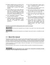
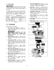
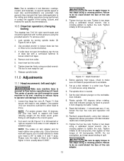
...: changing speeds NOTE: The 3-phase motor has an additional high and low-speed setting (H, Figure 7). 10.4 Fine feed 1. Verify that spindle brake is released before using this will add rigidity and provide for clamping work , keep table locking handles tightened. 3. Unscrew two knobs (A, Figure 7) and remove belt cover. 2. If using longitudinal table travel , keep head as close to column as required (Figure 9). Figure 8: controls 10.0 Operation 10.1 Precautions Observe the following instructions before starting motor...
...: changing speeds NOTE: The 3-phase motor has an additional high and low-speed setting (H, Figure 7). 10.4 Fine feed 1. Verify that spindle brake is released before using this will add rigidity and provide for clamping work , keep table locking handles tightened. 3. Unscrew two knobs (A, Figure 7) and remove belt cover. 2. If using longitudinal table travel , keep head as close to column as required (Figure 9). Figure 8: controls 10.0 Operation 10.1 Precautions Observe the following instructions before starting motor...
User Manual
Page 13
... manuals that secure mill head to support mill head, relieving weight off the brass worm gears. or contact the supplier of the ram adapter. 13 If collet does not open immediately, tap the top of worm gears. 2. Close tolerance work will lengthen life of draw bar with normal pressure using a crossing pattern. Put spindle drive in tool diameter, coatings, coolant, and materials, no specific spindle speed...
... manuals that secure mill head to support mill head, relieving weight off the brass worm gears. or contact the supplier of the ram adapter. 13 If collet does not open immediately, tap the top of worm gears. 2. Close tolerance work will lengthen life of draw bar with normal pressure using a crossing pattern. Put spindle drive in tool diameter, coatings, coolant, and materials, no specific spindle speed...

User Manual
Page 14
... saddle second, and adjust the table last. 11.3.1 Knee gib Loosen the two knee locking handles. Note: Use gentle hand pressure to eliminate most of movement in serious injury to operator and damage to floor before repositioning ram. A second feed screw nut is felt when turning longitudinal table cranks. Turn ram until spindle is recommended while performing heavy milling work, that lock ram to its ways...
... saddle second, and adjust the table last. 11.3.1 Knee gib Loosen the two knee locking handles. Note: Use gentle hand pressure to eliminate most of movement in serious injury to operator and damage to floor before repositioning ram. A second feed screw nut is felt when turning longitudinal table cranks. Turn ram until spindle is recommended while performing heavy milling work, that lock ram to its ways...

User Manual
Page 15
... indicator. The left hand nut is adjustable). 4. Tighten the two nut locking screws. 4. Figure 14: Lead screw backlash adjustment 15 Tighten the two nut locking screws. 7. Set up a dial indicator to tighten it against opposing nut. 6. Loosen the two nut locking screws. 5. Turn nut slightly to check longitudinal backlash. Install pleated way cover. 11.5.2 Longitudinal backlash adjustment Refer to tighten it against the opposing nut. 3. Turn the nut slightly to Figure 14: Only one of table. 1. This can...
... indicator. The left hand nut is adjustable). 4. Tighten the two nut locking screws. 4. Figure 14: Lead screw backlash adjustment 15 Tighten the two nut locking screws. 7. Set up a dial indicator to tighten it against opposing nut. 6. Loosen the two nut locking screws. 5. Turn nut slightly to check longitudinal backlash. Install pleated way cover. 11.5.2 Longitudinal backlash adjustment Refer to tighten it against the opposing nut. 3. Turn the nut slightly to Figure 14: Only one of table. 1. This can...
User Manual
Page 16
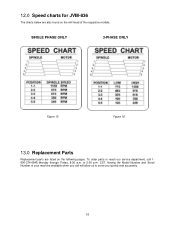
to serve you call 1800-274-6848 Monday through Friday, 8:00 a.m. 12.0 Speed charts for JVM-836 The charts below are listed on the mill head of your machine available when you quickly and accurately. 16 CST. To order parts or reach our service department, call will allow us to 5:00 p.m. Having the Model Number and Serial Number of the respective models. SINGLE PHASE ONLY 3-PHASE ONLY Figure 15 Figure 16 13.0 Replacement Parts Replacement parts are also found on the following pages.
to serve you call 1800-274-6848 Monday through Friday, 8:00 a.m. 12.0 Speed charts for JVM-836 The charts below are listed on the mill head of your machine available when you quickly and accurately. 16 CST. To order parts or reach our service department, call will allow us to 5:00 p.m. Having the Model Number and Serial Number of the respective models. SINGLE PHASE ONLY 3-PHASE ONLY Figure 15 Figure 16 13.0 Replacement Parts Replacement parts are also found on the following pages.
User Manual
Page 18
13.1.3 JVM-836 Head Assembly - Parts List Index No Part No Description Size Qty 1 JVM836-01 Castle Nut M12 1 2 JVM836-02 Lock Nut...1 3 TS-1523041 Hex Socket Cap Screw M6x12 3 4 JVM836-04 Cover ...1 5 JVM836-05 Taper Sleeve 1 6 JVM836-06 Spring ...1 7 JVM836-07 Transmission Sleeve (s/n 307XXXX and lower 1 8 JVM836-08 Worm Gear (s/n XXX0049 and lower 1 JVM836-08T Worm Gear (s/n 0040050 and higher 1 8A JVM836-08TN Worm Gear (s/n 307XXXX...
13.1.3 JVM-836 Head Assembly - Parts List Index No Part No Description Size Qty 1 JVM836-01 Castle Nut M12 1 2 JVM836-02 Lock Nut...1 3 TS-1523041 Hex Socket Cap Screw M6x12 3 4 JVM836-04 Cover ...1 5 JVM836-05 Taper Sleeve 1 6 JVM836-06 Spring ...1 7 JVM836-07 Transmission Sleeve (s/n 307XXXX and lower 1 8 JVM836-08 Worm Gear (s/n XXX0049 and lower 1 JVM836-08T Worm Gear (s/n 0040050 and higher 1 8A JVM836-08TN Worm Gear (s/n 307XXXX...
User Manual
Page 21
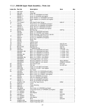
... M12x50 1 42 JVM836-42B Switch Assembly (1Ph 1 JVM836-42-3Ph ........ Switch Assembly (3Ph 1 21 13.2.2 JVM-836 Upper Head Assembly - Motor (s/n 2120611 and higher 1-1/2HP 3 Ph 1 VM-M25CS Centrifugal Switch (not shown 1 VM-M25RC Running Capacitor (not shown 25μF 350VAC 1 VM-M25SC Starting Capacitor (not shown 350MFD 350VAC.......... 1 24 VM-M21 Hex Head Screw M10x25 4 25 VM-M25-1 Flat Key 8x7x36 mm 1 26...
... M12x50 1 42 JVM836-42B Switch Assembly (1Ph 1 JVM836-42-3Ph ........ Switch Assembly (3Ph 1 21 13.2.2 JVM-836 Upper Head Assembly - Motor (s/n 2120611 and higher 1-1/2HP 3 Ph 1 VM-M25CS Centrifugal Switch (not shown 1 VM-M25RC Running Capacitor (not shown 25μF 350VAC 1 VM-M25SC Starting Capacitor (not shown 350MFD 350VAC.......... 1 24 VM-M21 Hex Head Screw M10x25 4 25 VM-M25-1 Flat Key 8x7x36 mm 1 26...

User Manual
Page 22
Index No Part No Description Size Qty 43 JVM836-43B Hex Socket Cap Screw M6x8 4 44 JVM836-44B Switch Cord (4C, 1Ph 1 JVM836-44-3Ph ........ Switch Cord (7C, 3Ph 1 45 VB-A29 Belt A29 1 46 VM-M26-1PH Spindle Speed Chart (1 Phase 1 VM-M26-3PH Spindle Speed Chart (3 Phase 1 48 VM-M2-1 Spring ...2 49 VM-M2-2 Cross Round Cap Screw 2 50 JVM836-U50 Plastic Electrical Box 1 51 JVM836-U51 Cross Round Cap Screw M5x40L 2 52 JVM836-N01 JET Label...1 22
Index No Part No Description Size Qty 43 JVM836-43B Hex Socket Cap Screw M6x8 4 44 JVM836-44B Switch Cord (4C, 1Ph 1 JVM836-44-3Ph ........ Switch Cord (7C, 3Ph 1 45 VB-A29 Belt A29 1 46 VM-M26-1PH Spindle Speed Chart (1 Phase 1 VM-M26-3PH Spindle Speed Chart (3 Phase 1 48 VM-M2-1 Spring ...2 49 VM-M2-2 Cross Round Cap Screw 2 50 JVM836-U50 Plastic Electrical Box 1 51 JVM836-U51 Cross Round Cap Screw M5x40L 2 52 JVM836-N01 JET Label...1 22
User Manual
Page 26
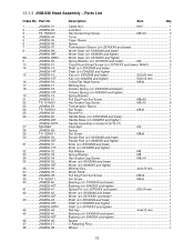
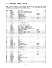
... Stud (serial # 0040064 & higher M12x115 4 18 JVM836-18B Adjustable Screw 6 19 TS-1523021 Set Screw M6x10 2 19-1 ...........TS-1540041 Hex Nut M6 2 20 VM-L4 Lock Handle M10x40 5 20-1 VM-L4-1 Shoe ...2 21 VM-L7 Graduated Scale 1 22 VM-L7-1 Rivet 2 mm 7 23 VM-K11 Spider Arm ...1 24 VM-K9 Base...1 25 VM-K17 Limit plate ...2 26 VM-K5 Plate...1 27...
... Stud (serial # 0040064 & higher M12x115 4 18 JVM836-18B Adjustable Screw 6 19 TS-1523021 Set Screw M6x10 2 19-1 ...........TS-1540041 Hex Nut M6 2 20 VM-L4 Lock Handle M10x40 5 20-1 VM-L4-1 Shoe ...2 21 VM-L7 Graduated Scale 1 22 VM-L7-1 Rivet 2 mm 7 23 VM-K11 Spider Arm ...1 24 VM-K9 Base...1 25 VM-K17 Limit plate ...2 26 VM-K5 Plate...1 27...

User Manual
Page 27
... Holder ...1 VM-H5TA Dial Holder Assembly (includes #66,67,68,69,71,90 1 67 VM-H3 Dial...1 VM-H3T Dial...1 68 VM-H2 Knurled Nut...1 VM-H2T Knurled Nut...1 69 VM-H4 Clutch Insert 1 VM-H4T Clutch Insert 1 71 VM-H1 Hand Lever ...1 VM-H1T Hand Lever ...1 73 VM-H1-3 Hand Grip ...1 74 VM-H24 Straight Bevel Gear (s/n XXX0049 and lower 1 VM-H24T Helical Bevel Gear...
... Holder ...1 VM-H5TA Dial Holder Assembly (includes #66,67,68,69,71,90 1 67 VM-H3 Dial...1 VM-H3T Dial...1 68 VM-H2 Knurled Nut...1 VM-H2T Knurled Nut...1 69 VM-H4 Clutch Insert 1 VM-H4T Clutch Insert 1 71 VM-H1 Hand Lever ...1 VM-H1T Hand Lever ...1 73 VM-H1-3 Hand Grip ...1 74 VM-H24 Straight Bevel Gear (s/n XXX0049 and lower 1 VM-H24T Helical Bevel Gear...


