
Instruction Manual
Page 2
... remove cover. MACHINE NOISE INFORMATION (Germany only) Changes Machine Noise Information Ordinance 3. About the installation place Do not install the projector in a residential installation. For disposal or recycling information, please contact your community due to insert the plug into an outlet on , the user is equipped with the limits for help. CAUTION: To reduce the risk of Conformity Model Number: DLA-RS6710U/DLA-RS4910U...
... remove cover. MACHINE NOISE INFORMATION (Germany only) Changes Machine Noise Information Ordinance 3. About the installation place Do not install the projector in a residential installation. For disposal or recycling information, please contact your community due to insert the plug into an outlet on , the user is equipped with the limits for help. CAUTION: To reduce the risk of Conformity Model Number: DLA-RS6710U/DLA-RS4910U...
Instruction Manual
Page 3
... left unattended and unused for its surrounding as an improper adjustment of this indicates a need for cleaning. - Adjust only those controls that the internal and external temperatures are covered by the Operation Manual, as shown below , use a mount recommended by RETAC) care should be routed so that the product is damaged. When replacement parts are not likely to insert the plug into this...
... left unattended and unused for its surrounding as an improper adjustment of this indicates a need for cleaning. - Adjust only those controls that the internal and external temperatures are covered by the Operation Manual, as shown below , use a mount recommended by RETAC) care should be routed so that the product is damaged. When replacement parts are not likely to insert the plug into this...
Instruction Manual
Page 4
... the length and frequency of time it may cause the light-source lamp to break and lead to performance degradation. - Use only the accessory cord designed for proper display. normal video footage. - If anything is suspended from watching any 3D-images when you feel any way. Video images can burn into the projection lens while the illumination lamp is turned on frequency of said metal...
... the length and frequency of time it may cause the light-source lamp to break and lead to performance degradation. - Use only the accessory cord designed for proper display. normal video footage. - If anything is suspended from watching any 3D-images when you feel any way. Video images can burn into the projection lens while the illumination lamp is turned on frequency of said metal...

Instruction Manual
Page 5
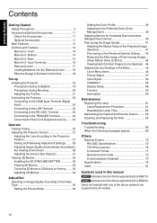
Getting Started POWER CONNECTION For USA and Canada only Use only the following cord: Green-and-yellow : Earth Blue : Neutral Brown : Live As these colors may not correspond with the colored making identifying the terminals in your country. Use only the power cord designated by inadvertent connection to the terminal which is : JVC Technical Services Europe GmbH Konrad-Adenauer-Allee 1-11 61118 Bad Vilbel Germany . 5 IMPORTANT (Europe...
Getting Started POWER CONNECTION For USA and Canada only Use only the following cord: Green-and-yellow : Earth Blue : Neutral Brown : Live As these colors may not correspond with the colored making identifying the terminals in your country. Use only the power cord designated by inadvertent connection to the terminal which is : JVC Technical Services Europe GmbH Konrad-Adenauer-Allee 1-11 61118 Bad Vilbel Germany . 5 IMPORTANT (Europe...
Instruction Manual
Page 10
... Menu Items 45 Picture Adjust 47 Input Signal 50 Installation 52 Display Setup 58 Function 59 Information 60 Maintenance Replacing the Lamp 61 Lamp Replacement Procedure 61 Resetting the Lamp Time 63 Maintaining the Cabinet and Remote Control ........ 63 Cleaning and Replacing the Filter 64 Troubleshooting Troubleshooting 65 When the following messages appear 69 Others External Control 70 RS-232C Specifications 70 TCP/IP Connection 70 Command Format 71 Remote Control Code 72 Communications Example 73 Specifications 74 Index 81 Symbols used...
... Menu Items 45 Picture Adjust 47 Input Signal 50 Installation 52 Display Setup 58 Function 59 Information 60 Maintenance Replacing the Lamp 61 Lamp Replacement Procedure 61 Resetting the Lamp Time 63 Maintaining the Cabinet and Remote Control ........ 63 Cleaning and Replacing the Filter 64 Troubleshooting Troubleshooting 65 When the following messages appear 69 Others External Control 70 RS-232C Specifications 70 TCP/IP Connection 70 Command Format 71 Remote Control Code 72 Communications Example 73 Specifications 74 Index 81 Symbols used...

Instruction Manual
Page 14
... image is also a remote sensor at this area when using it when you need to 5 mm) (p. 21) When the foot is used as the mounting holes for the ceiling mount bracket. 14 G Manual button for maintenance purposes. Front D E E C AB . Main Unit - B Lens cover Z The lens cover opens/closes when the power supply is turned on/off. (p. 52) 0 For Y, attach the lens cover when the unit is not in air to "Indicator Display...
... image is also a remote sensor at this area when using it when you need to 5 mm) (p. 21) When the foot is used as the mounting holes for the ceiling mount bracket. 14 G Manual button for maintenance purposes. Front D E E C AB . Main Unit - B Lens cover Z The lens cover opens/closes when the power supply is turned on/off. (p. 52) 0 For Y, attach the lens cover when the unit is not in air to "Indicator Display...
Instruction Manual
Page 21
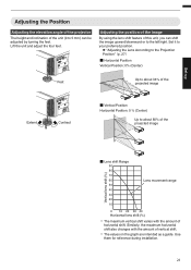
...guide. Similarly, the maximum horizontal shift also changes with the amount of the unit (0 to 5 mm) can shift the image upward/downward or to about 34% of the Feet projected image Extend . Use them for reference during installation. 21 Set up Adjusting the Position Adjusting the elevation angle of the projector...of the projected image Vertical lens shift (%) ˙ Lens shift Range 90 80 70 60 50 40 30 20 10 Lens movement range 0 10 20 30 40 Horizontal lens shift (%) . 0 The maximum vertical shift varies with the amount of this unit, you can be adjusted by turning the feet....
...guide. Similarly, the maximum horizontal shift also changes with the amount of the unit (0 to 5 mm) can shift the image upward/downward or to about 34% of the Feet projected image Extend . Use them for reference during installation. 21 Set up Adjusting the Position Adjusting the elevation angle of the projector...of the projected image Vertical lens shift (%) ˙ Lens shift Range 90 80 70 60 50 40 30 20 10 Lens movement range 0 10 20 30 40 Horizontal lens shift (%) . 0 The maximum vertical shift varies with the amount of this unit, you can be adjusted by turning the feet....
Instruction Manual
Page 26
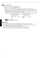
... "STANDBY/ON" indicator switches from a green light to a red blinking light. 0 After the light goes off , the fan will run for about 100 seconds to turn off?" 3 Turn off the power Remote control: press the B [STAND BY] button Projector unit: press the A [STANDBY/ON] button 0 While the "Are you sure you want to cool down the lamp (Cool-down mode "STANDBY/ON" lights up (red) In standby state STANDBY/ON LAMP WARNING STANDBY/ON LAMP WARNING . 0 (Y) Attach the lens cover. 0 (Z) The motorized lens cover opens. "STANDBY/ON" blinking (red...
... "STANDBY/ON" indicator switches from a green light to a red blinking light. 0 After the light goes off , the fan will run for about 100 seconds to turn off?" 3 Turn off the power Remote control: press the B [STAND BY] button Projector unit: press the A [STANDBY/ON] button 0 While the "Are you sure you want to cool down the lamp (Cool-down mode "STANDBY/ON" lights up (red) In standby state STANDBY/ON LAMP WARNING STANDBY/ON LAMP WARNING . 0 (Y) Attach the lens cover. 0 (Z) The motorized lens cover opens. "STANDBY/ON" blinking (red...

Instruction Manual
Page 36
... "Picture Mode" Y Picture Mode 2D Signal Input 3D Signal Input Description Cinema Cinema - Stage Stage - User 1 to User 4 Standard Cinema Animation When "Picture Mode" is set to any of the settings from "Picture Adjust"""Color Profile" in videos; PHOTO 0 The selectable "Color Profile" settings vary according to "User 4", you can select one of the "Color Profile" shown on the left. 0 See above for High Definition Television. *2 To view videos that support the x.v.Color format, select a user setting ("User 1" to "User 4") in...
... "Picture Mode" Y Picture Mode 2D Signal Input 3D Signal Input Description Cinema Cinema - Stage Stage - User 1 to User 4 Standard Cinema Animation When "Picture Mode" is set to any of the settings from "Picture Adjust"""Color Profile" in videos; PHOTO 0 The selectable "Color Profile" settings vary according to "User 4", you can select one of the "Color Profile" shown on the left. 0 See above for High Definition Television. *2 To view videos that support the x.v.Color format, select a user setting ("User 1" to "User 4") in...
Instruction Manual
Page 39
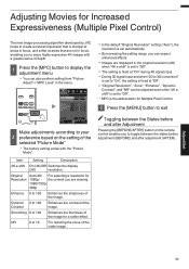
... Switches the display (2K) resolution. Adjust/Set 39 INPUT Picture Adjust >> MPC Level 4K e-shift On Original Resolution Auto Enhance 0 Dynamic Contrast 0 Smoothing 0 NR 0 Before Reset Exit MENU Select Operate Back BACK . Dynamic 0 to 100 Contrast Enhances the contrast of the image for a softer effect. Smoothing 0 to 100 Enhances the blurriness of the image. Adjusting Movies for Increased Expressiveness (Multiple Pixel Control) The new image-processing algorithm developed by JVC helps...
... Switches the display (2K) resolution. Adjust/Set 39 INPUT Picture Adjust >> MPC Level 4K e-shift On Original Resolution Auto Enhance 0 Dynamic Contrast 0 Smoothing 0 NR 0 Before Reset Exit MENU Select Operate Back BACK . Dynamic 0 to 100 Contrast Enhances the contrast of the image for a softer effect. Smoothing 0 to 100 Enhances the blurriness of the image. Adjusting Movies for Increased Expressiveness (Multiple Pixel Control) The new image-processing algorithm developed by JVC helps...

Instruction Manual
Page 44
....] button each time switches the mode in the image. Reducing the After-image of Fast-moving Images (Clear Motion Drive (C.M.D.)) Optimal interpolation according to the content is changed to Auto after performing manual adjustment, the value set to enjoy video images with the new high-definition image interpolation technique that supports 3D images. In this setting to the image information. Suitable for Auto. 44 Auto 2 Places emphasis on the model in use. (p. 17) Viewing High Contrast Images (Lens Aperture) JVC...
....] button each time switches the mode in the image. Reducing the After-image of Fast-moving Images (Clear Motion Drive (C.M.D.)) Optimal interpolation according to the content is changed to Auto after performing manual adjustment, the value set to enjoy video images with the new high-definition image interpolation technique that supports 3D images. In this setting to the image information. Suitable for Auto. 44 Auto 2 Places emphasis on the model in use. (p. 17) Viewing High Contrast Images (Lens Aperture) JVC...
Instruction Manual
Page 46
...52 9 Lens Memory Select ...p. 28 9 Lens Memory Save ...p. 28 9 Lens Memory Name Edit ...p. 28 9 Lens Center ...p. 52 9 Lens Cover Z ...p. 52 I Pixel Adjust ...p. 53 I Installation Style ...p. 54 I Keystone ...p. 54 I Pincushion ...p. 54 I Anamorphic ...p. 54 I High Altitude Mode ...p. 54 I Environment Setting ...p. 30 9 Screen Adjust ...p. 30 Display Setup I Back Color ...p. 58 I Menu Position ...p. 58 I Signal Display ...p. 58 I Logo ...p. 58 I Language ...p. 58 Function I Trigger ...p. 59 I Off Timer ...p. 59 I ECO Mode ...p. 59 I Network ...p. 59 I Remote Code ...p. 60 I Lamp Reset ...p. 63...
...52 9 Lens Memory Select ...p. 28 9 Lens Memory Save ...p. 28 9 Lens Memory Name Edit ...p. 28 9 Lens Center ...p. 52 9 Lens Cover Z ...p. 52 I Pixel Adjust ...p. 53 I Installation Style ...p. 54 I Keystone ...p. 54 I Pincushion ...p. 54 I Anamorphic ...p. 54 I High Altitude Mode ...p. 54 I Environment Setting ...p. 30 9 Screen Adjust ...p. 30 Display Setup I Back Color ...p. 58 I Menu Position ...p. 58 I Signal Display ...p. 58 I Logo ...p. 58 I Language ...p. 58 Function I Trigger ...p. 59 I Off Timer ...p. 59 I ECO Mode ...p. 59 I Network ...p. 59 I Remote Code ...p. 60 I Lamp Reset ...p. 63...
Instruction Manual
Page 59
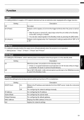
... V) from the trigger terminal when the power is turned on. 0 After the power is used in the Standby mode by pressing the [OK] button. Outputs control signals when the "Anamorphic" setting is complete. 0 You can also output signals in the Standby mode. For configuring the network settings manually. For configuring the default gateway. Network Specify the settings below during external control such as an external screen equipped with a trigger function. For...
... V) from the trigger terminal when the power is turned on. 0 After the power is used in the Standby mode by pressing the [OK] button. Outputs control signals when the "Anamorphic" setting is complete. 0 You can also output signals in the Standby mode. For configuring the network settings manually. For configuring the default gateway. Network Specify the settings below during external control such as an external screen equipped with a trigger function. For...

Instruction Manual
Page 60
... blinks 2 times: change the remote control code to "B" Setting A B Description Change the remote control code from "B" to "A". This is a number that is unique to each network adapter. Change the remote control code from "A" to the settings of the network adapters is assigned with a unique MAC address. Displays the version of the input signal. MAC Address : Abbreviation for identifying the device that is connected to "0". Æ "Resetting the Lamp Time"(p. 63) Information Setting Description Input Displays video input terminal. Displays the firmware...
... blinks 2 times: change the remote control code to "B" Setting A B Description Change the remote control code from "B" to "A". This is a number that is unique to each network adapter. Change the remote control code from "A" to the settings of the network adapters is assigned with a unique MAC address. Displays the version of the input signal. MAC Address : Abbreviation for identifying the device that is connected to "0". Æ "Resetting the Lamp Time"(p. 63) Information Setting Description Input Displays video input terminal. Displays the firmware...
Instruction Manual
Page 62
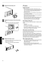
... goes out varies considerably with a different product number or those for a prolonged period of its usable life, deterioration progresses rapidly. 0 When the video image appears dark, when the color tone looks unnatural, or when the image flickers, replace the lamp unit with "Lamp Power" set to shock or after using for other projector models cannot be used in the same way as the operating conditions). Maintenance 62
... goes out varies considerably with a different product number or those for a prolonged period of its usable life, deterioration progresses rapidly. 0 When the video image appears dark, when the color tone looks unnatural, or when the image flickers, replace the lamp unit with "Lamp Power" set to shock or after using for other projector models cannot be used in the same way as the operating conditions). Maintenance 62

Instruction Manual
Page 63
... may deteriorate in the Standby mode (the power plug is inserted into the power outlet Make sure that , the unit switches to display the menu 2 Select "Function"""Lamp Reset" from the menu Trigger Off Timer ECO Mode Network Remote Code Lamp Reset Function Off Off Off A Resetting the lamp time using the lamp beyond the estimated limit, thereby causing lamp blowout. Resetting the Lamp Time Reset the lamp time when you have replaced the lamp. It provides an estimated timing for replacing the lamp.
... may deteriorate in the Standby mode (the power plug is inserted into the power outlet Make sure that , the unit switches to display the menu 2 Select "Function"""Lamp Reset" from the menu Trigger Off Timer ECO Mode Network Remote Code Lamp Reset Function Off Off Off A Resetting the lamp time using the lamp beyond the estimated limit, thereby causing lamp blowout. Resetting the Lamp Time Reset the lamp time when you have replaced the lamp. It provides an estimated timing for replacing the lamp.
Instruction Manual
Page 68
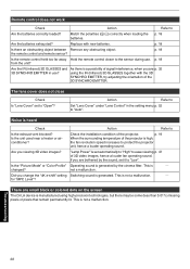
... surrounding temperature of 3D video images, hence a louder fan operating sound. "Lamp Power" is generated by the sound, set it to "Auto". Is the unit used near a heater or airconditioner? for "MPC Level"? There are p. 32 3D SYNCHRO EMITTER in the setting menu p. 52 to "Low". The lens cover does not close Check Is "Lens Cover" set automatically to "High" to "Open"? changed? Remote control does not work Check Action Refer to the sensor during use ? the remote control and remote...
... surrounding temperature of 3D video images, hence a louder fan operating sound. "Lamp Power" is generated by the sound, set it to "Auto". Is the unit used near a heater or airconditioner? for "MPC Level"? There are p. 32 3D SYNCHRO EMITTER in the setting menu p. 52 to "Low". The lens cover does not close Check Is "Lens Cover" set automatically to "High" to "Open"? changed? Remote control does not work Check Action Refer to the sensor during use ? the remote control and remote...

Instruction Manual
Page 78
... projection STANDBY/ON LAMP WARNING STANDBY/ON LAMP WARNING STANDBY/ON LAMP WARNING "STANDBY/ON" blinking (red) In the Cool-down mode STANDBY/ON LAMP WARNING "STANDBY/ON" blinking (green) When the video image is temporarily hidden (HIDE is near STANDBY/ON LAMP WARNING (lamp time has exceeded 2900 hours) . "LAMP" lights up . Others 78 The "STANDBY/ON" indicator, which shows the operating mode of the "STANDBY/ON" indicator. Operation mode display Displays using the solid/blinking light of the lighting figures The indicator lights up (orange) When lamp replacement...
... projection STANDBY/ON LAMP WARNING STANDBY/ON LAMP WARNING STANDBY/ON LAMP WARNING "STANDBY/ON" blinking (red) In the Cool-down mode STANDBY/ON LAMP WARNING "STANDBY/ON" blinking (green) When the video image is temporarily hidden (HIDE is near STANDBY/ON LAMP WARNING (lamp time has exceeded 2900 hours) . "LAMP" lights up . Others 78 The "STANDBY/ON" indicator, which shows the operating mode of the "STANDBY/ON" indicator. Operation mode display Displays using the solid/blinking light of the lighting figures The indicator lights up (orange) When lamp replacement...

Instruction Manual
Page 79
... the scheduled time for about 100 seconds. Countermeasure: Turn on for lamp replacement is exceeded, the indicator may light up and unit is 0 Check that nothing is normal. x5 Abnormality in progress. Abnormal circuit operation After that the external Internal temperature is abnormally temperature is blocking Cooling fan stopped abnormally the air inlets. 0 Check that , turn on the power again. x1 STANDBY/ON LAMP WARNING x2 Mode (Orange) (Red) x3 Display . Warning display You...
... the scheduled time for about 100 seconds. Countermeasure: Turn on for lamp replacement is exceeded, the indicator may light up and unit is 0 Check that nothing is normal. x5 Abnormality in progress. Abnormal circuit operation After that the external Internal temperature is abnormally temperature is blocking Cooling fan stopped abnormally the air inlets. 0 Check that , turn on the power again. x1 STANDBY/ON LAMP WARNING x2 Mode (Orange) (Red) x3 Display . Warning display You...

Instruction Manual
Page 81
... External Control 70 F Filter Product no 64 Filter Replacement 64 Focus 28 Frame Interpolation 44 Frame Packing 33 G GAMMA 41 Gamma Adjustment 41 H HDMI Color Space 50 HDMI Input Level 50 HDMI Input Link 50 HDMI Input Terminal 22 HIDE 25 High Altitude Mode 54 I Indicator Display 78 INFO 17 Input Resolution 60, 77 Input Signal 60, 77 Input terminals 16 Installation Method 19 Installing the 3D Syncro Emitter 32 K Keystone Correction 54 L Lamp 11 Lamp Power 47 Lamp Time 60...
... External Control 70 F Filter Product no 64 Filter Replacement 64 Focus 28 Frame Interpolation 44 Frame Packing 33 G GAMMA 41 Gamma Adjustment 41 H HDMI Color Space 50 HDMI Input Level 50 HDMI Input Link 50 HDMI Input Terminal 22 HIDE 25 High Altitude Mode 54 I Indicator Display 78 INFO 17 Input Resolution 60, 77 Input Signal 60, 77 Input terminals 16 Installation Method 19 Installing the 3D Syncro Emitter 32 K Keystone Correction 54 L Lamp 11 Lamp Power 47 Lamp Time 60...


